the Creative Commons Attribution 4.0 License.
the Creative Commons Attribution 4.0 License.
Infrared-based sensor system for contactless monitoring of wetness and ice
Lakshan Tharmakularajah
Jakob Döring
Karl-Ludwig Krieger
In order to differentiate between a wet and a dry road surface, the water film height should be measured by using an infrared-based sensor system. By means of different wavelengths, it is also possible to distinguish between ice and water. In this article, a sensor system for the determination of the physical state of water on different surfaces using infrared LEDs and one photodiode is presented. This shall serve as a basis for the calculation of the road condition. Here, emitted and reflected signals of five different infrared emitters are acquired with an infrared receiver. In commercial sensors this method (operating with one emitter) is used to determine a distance. At a constant distance, different intensities of the reflected signal are measured depending on the colour and texture of the surface. Similar sensor systems work with a broadband light, usually a halogen lamp, and several photodiodes. This type of sensor system is more cost-intensive and not robust enough for the desired application. The transmission spectrum of water shows that light is absorbed at a wavelength of 900 nm and strongly at a wavelength of about 1.4–1.5 µm. From the absorption spectrum of ice, it can be concluded that the wavelengths up to 1.4 µm are absorbed less than the wavelength at 1.5 µm. Therefore, the intensity depends not only on the material surface, but also on the wavelength of the transmitting and receiving diode. In order to distinguish between ice and water, the intensities of the light at the wavelengths 1.45 and 1.55 µm are compared, which is shown in this article by the measurements. In ice, the infrared light is more strongly absorbed at 1.55 µm.
- Article
(7133 KB) - Full-text XML
- BibTeX
- EndNote
Common causes of personal injury in traffic are due to poor road conditions (Destatis, 2018). Between 2014 and 2017, slippery roads caused around 45 900 accidents in Germany due to rain, snow and ice. That is around 3.5 % to 4.1 % of all accidents with personal injury in Germany and the trend is rising. Drivers regularly lose control of their vehicle due to slippery roads. As a result, the demand for technologies that reliably detect critical road conditions of this kind is growing. Environmental detection and knowledge of road conditions are becoming more important as automation increases in the automotive sector. They are essential for autonomous driving in demanding weather conditions. The environmental sensors already installed in vehicles are not sufficient, as they can only indirectly determine road conditions. For example, the rain-light sensor can only be used on a wet road surface when it is raining. After it has stopped raining, the road is still wet, but this cannot be diverted on a wet road. There are also approaches of indirect road condition monitoring available, as for example the use of capacitive sensors on the wheel arch liner (Döring et al., 2019). To monitor the road surface, directly visible image sensors, infrared image sensors and millimetre-wave radar sensors are used (Kurata et al., 2004). These sensors are complex and partly not suitable for vehicles. Therefore, the motivation is to determine the water film height with an in-house developed sensor. The technology for the determination of ice and water through infrared has already been developed (Holzwarth and Eichhorn, 1993). However, expensive spectrometers are used for the analyses. By Jonsson (2011), three photodiodes were used as a receiver and a broadband 20 W halogen lamp was used as the light source for the measurements. This method (operating with one emitter and receiver) is used to determine a distance with commercially available sensors (Schrey et al., 2005). In this approach, a broadband photodiode and five selected LEDs with defined wavelengths are used as a light source. To extract the five LEDs from the photodiode signal, they are pulsed with different modulation frequencies via a microcontroller.
The aim of the sensor system is to detect wetness or water on a surface and to record the height of the water film. Furthermore, only one broadband photodiode is used. For the selection of suitable LEDs, the wavelengths in the transmission spectrum of water and the absorption spectrum of ice are considered. A theoretical approach implies that due to the presence of a water film on a surface, the light intensity of the wavelength with a high transmittance decreases less than the intensity with a low transmittance (Holzwarth and Eichhorn, 1993). In Klempau (2003) the comparison of light at the wavelengths 1.4 and 1.5 µm for ice detection is described. From the absorption spectrum of ice, it can be concluded that light at the wavelengths up to 1.4 µm is absorbed less than light of the wavelength at 1.5 µm. Figure 1 shows the transmittance spectrum (blue solid line) and the absorption spectrum (red dashed line). According to the transmission spectrum of water, light at a wavelength of 1 to 1.1 µm is transmitted about 80 %, from 1.17 to 1.3 µm about 53 % to 58 %. In the range from 1.4 to 1.55 µm the light is only transmitted about 2 %. The absorption spectrum of ice shows that light at a wavelength of about 1.5 µm is absorbed more strongly than light in the range of 1.0 to 1.4 µm. Conversely, light at a wavelength of 1.5 µm is transmitted less than the remaining light. By comparing the transmittance of water and the absorbance of ice, it can be shown that in particular the transmittance at the wavelengths of 1.4 and 1.5 µm can give information about the state of aggregation of water.
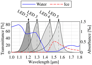
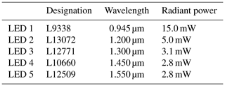
To build the sensor system, five different LEDs are selected as the light source and one photodiode is used as the receiver. The LEDs were selected to ensure that each light is transmitted and absorbed differently by water and ice. Since LED 1 lies outside the shown transmission spectrum, its emission spectrum is described below. However, this has an emission spectrum of 0.92 to 0.97 µm and the highest intensity is at 0.945 µm. Figure 1 shows that the emission spectra of LED 2 to 5 overlap.
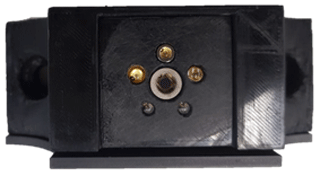
Still, these have their highest intensity at different wavelengths as shown in Table 1. The LEDs are arranged in a circle with the same distance to the photodiode, so that they have a similar influence. To extract the signals of the LEDs, in the signal of the photodiode, the LEDs are pulsed with different frequencies. This sensor system is shown in Fig. 2 The selected photodiode (G12180-030) is used as receiver. The photodiode consists of the semiconductor material indium gallium arsenide also referred to as InGaAs photodiode. This has a round, light-sensitive surface with a diameter of 0.3 mm, which reacts in a wavelength range of 0.9 to 1.7 µm.
2.1 Frequency-division multiple access
The current of the PD is converted into a voltage through a transimpedance amplifier and measured over an ADC. For example, the modulation frequency of LED 1 is 2.43 kHz with a duty cycle of 50 %. LED 2 is driven at 3.89 kHz and also has a duty cycle of 50 %. The modulation frequency must be selected to ensure that the LEDs have sufficient time to completely build up and release their light output. It is also important for the frequency that the harmonic frequencies do not overlay. In order to reduce additional interferences, the modulation frequency should not harmonize with the mains frequency. First, the LEDs were considered individually. Figure 4 shows the respective results in the time domain (a) and in the frequency domain (b). The representation of the results in the time domain shown in Fig. 4a shows the rectangular carrier frequency for both measurements. Figure 4b clearly shows the modulated amplitudes at the respective frequencies. Compared to the amplitudes of the time domain, the amplitudes in the frequency domain decrease by a factor of 2π−1 at the respective excitation frequencies. Further harmonic frequencies with low amplitudes are also shown. In the frequency domain, a DC voltage part at 0 kHz is recognizable for both measurements. This can be explained by the fact that the LEDs are switched on and off by the pulse-width modulation (PWM), and thus only positive voltages are present after the transimpedance conversion. The duty cycle of 50 % results in an average rectified value of half the amplitude at 0 kHz. In order to investigate the behaviour of the sensor system with respect to amplitude modulation and the frequency division multiplex method, a further measurement is considered. In this measurement, LED 1 with 2.43 kHz and LED 2 with 3.89 kHz are not driven sequentially but simultaneously. Figure 3 shows the result of the measurement in the time domain (a) and frequency domain (b).
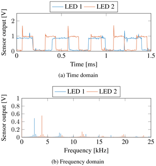
Figure 3Amplitude modulation and frequency division multiplexing with sequential control of LED 1 and LED 2.
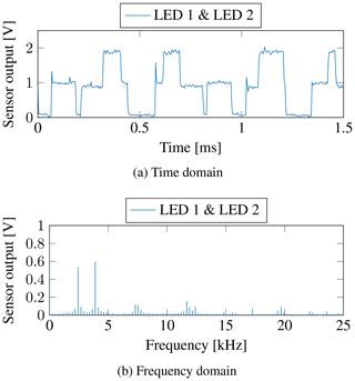
Figure 4Amplitude modulation and frequency division multiplexing with simultaneous control of LED 1 and LED 2.
In the time domain, Fig. 3a shows the additive interference of the modulated rectangular voltages of LED 1 and LED 2. In comparison to the separate measurements, the same amplitude is recognizable in the frequency domain at the respective frequencies. The average rectified value at 0 kHz also results from the additive superposition.
The amplitude modulation and the frequency division multiplex method can be evaluated by comparing the successive and simultaneous control of the LEDs. Due to the additive interference of the radiation powers, the combination of amplitude modulation and frequency division multiplexing proves to be suitable. Therefore, only one broadband photodiode is required for the reception of several LEDs. In particular, this results in a multitude of further possibilities, since the carrier frequency is important rather than the wavelength of the LEDs. One possibility would be to pulse the LEDs with different frequencies at the same wavelength to investigate different viewing angle and orientation to the surface. Furthermore, the reflection and absorption of the light at the same wavelength can be measured simultaneously and independently of each other.
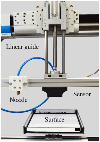
In this section, the setup of the measurement environment is presented. For the measurements, a test bench was set up which sprays a water film with a defined height in 1 mm steps onto a surface. The test bench shown in Fig. 5 can be controlled in horizontal and vertical direction with a resolution of 1 mm. In order to reproducibly generate water film heights with an accuracy of 1 mm, a strain gage balance was implemented under the surface. The strain gage balance measures the weight, while a pump applies a fine spray to the surface. According to Eq. (1), the given density ρ of the water allows the weight m to be calculated into the volume
By the calculated volume V and a given surface of a tile a⋅b the water film height
can be determined. In this case a=b. Therefore, the area of the surface is a2. The white and black tiles measuring 20 cm × 20 cm are used for the tests. Boundaries were placed on the sides of the surfaces to prevent sprayed water from overflowing.
In this section, the performed experiments and results are presented. In order to be able to make tangible statements on the individual changed parameters of the distance and the surface, a protection against extraneous light is used. First, two differently coloured surfaces, a white and a black tile, were examined. The measurements were carried out on a dry surface to investigate the influence of the different surface properties. In this case, the surfaces in a dry state with a water film height of 0 mm were investigated. The intensities of the individual LEDs were measured from 5 to 15 cm in 1 cm steps. Subsequently, measurements on wet surfaces were carried out. A water film height of 1 to 10 mm was measured in 1 mm steps at a distance of 5 cm on the white surface. Finally, ice on the white surface with a thickness of 1 mm was measured with the sensor system and compared with water.
4.1 Distance and intensity analysis
The measurements were performed at a distance, between the sensor and the surface, of 5 to 15 cm in 1 cm steps. The measurement results are shown in Figs. 6 and 8. For all steps five measurements with 10 s each were performed. The measurement data were acquired with a sampling rate of 500 kHz and then averaged. The light emitted by the LEDs was reflected by the two different surfaces and converted into a current by the photodiode. A voltage was generated by a transimpedance converter, which was digitally acquired. At a distance from 5 to 15 cm from the surface, different intensities of each LED could be observed.
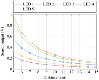
Figure 6Sensor output at different distances from 5 to 15 cm in 1 cm step with the white tile surface without water.
On the one hand this can be attributed to the different spectral sensitivity of the photodiode and on the other hand to the different radiant powers of the LEDs listed in Table 1. LED 1 has the highest radiant power, but it has the shortest wavelength. This results in increased reflections at the surface molecules. Due to the coarseness of the tile, the light beams of LED 1 are not reflected uniformly but scattered. This means that fewer photons reaching the sensitive area of the photodiode and, therefore, the intensity is lower. In addition, the spectral transmission of the protective glass and the sensitivity of the photodiode contribute to LED 2 having the highest intensity value and LED 4 the lowest intensity value.
By observing the course of the intensities I with increasing distance r, it is possible to recognize that these follow the inverse-square law of distance. The inverse-square law describes the decrease of a physical quantity with increasing distance to the source or transmitter (Harten, 2014).
This behaviour is more clearly recognizable by the representation of the relative intensity to the smallest distance on a white surface. Figure 7 shows that the intensities of all LEDs decrease quadratically with increasing distance. The intensity is reduced to a quarter of the initial intensity when the distance is doubled from 5 to 10 cm. Analogous to the measurements with the white surface, the measurements and results with the black surface are considered in the following. Figure 8 shows the measured intensities at different distances to the black surface. Here it can be seen that the order of the intensity of the individual LEDs was almost identical for white and black tiles. The light of LED 2 is reflected most strongly and the light of LED 4 most weakly from the black surface back to the photodiode. LED 1 and LED 3 have an almost identical behaviour.
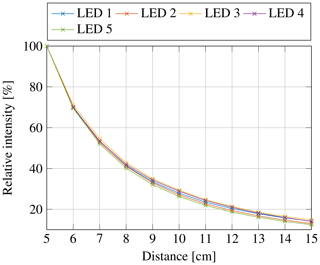
Figure 7Relative intensity decrease at distances of 5 to 15 cm with white tile surface without water.
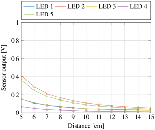
Figure 8Sensor output at different distances from 5 to 15 cm in 1 cm step with the black tile surface without water.
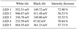
The direct comparison of the intensity values between the white and black surface at a distance of 5 cm shows a difference. This difference is due to the increased reflectivity of the white surface and the increased absorption of the black surface. A quantification of the values at a distance of 5 cm for the white and black surface and the resulting decrease in intensity are given in Table 2. The intensity of LED 2, 3 and 5 are absorbed almost uniformly by the surface of the black tile. LED 1 and 4 show a decrease in intensity of 70 %. The wavelength-dependent refractive index and the absorption behaviour of the black surface could be decisive for this.
4.2 Investigation of water film heights
The measurements are carried out at a fixed distance of 5 cm between sensor and surface. A water film layer of 1 to 10 mm was applied to the substrate in 1 mm steps. The measured intensity values of the individual LEDs for water film height from 0 to 10 mm with a sensor distance of 5 cm are shown in Fig. 9. The water film height of 0 mm describes the dry condition of the surface. The measurement with a water film height of 1 mm shows that the intensity of the individual LEDs decreases. This decrease in intensity can be explained by the light beam path described in Tharmakularajah et al. (2019). The light beam is not only reflected on the surface of the ground, but also first partially reflected on the water surface. The transmitted light beam is partly absorbed by water. The strength of the absorption is different for each wavelength of the LEDs. The light beam is then reflected at the surface of the substrate, absorbed again by the water, refracted at the transition between water and air, and received by the photodiode.
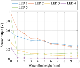
Figure 9Measurements of water film heights from 1 to 10 mm on a white tile surface at a distance of 5 cm.
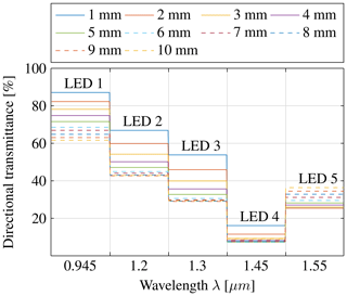
In general, the light with the shorter wavelengths 0.945, 1.2 and 1.3 µm decrease less than that of the longer wavelengths 1.45 and 1.55 µm. This is due to the fact that light with the wavelengths 0.945, 1.2 and 1.3 µm is more effectively transmitted by water and light with the wavelengths 1.45 and 1.55 µm is more strongly absorbed by water. By analysing the progression with increasing water film height, it can be observed that the measurement at the water film height of 4 mm shows a slight measurement deviation. The intensity of LED 5 with a wavelength of 1.55 µm increases from a water film height of 2 mm. This increase in intensity suggests that the reflective component on the surface of the water is higher than the transmission and absorption component. So the light gets absorbed completely after 2 mm and the reflection dominates. As the distance between sensor and water surface decreases, the intensity values of LED 5 increase. For detailed analyses of the intensity change, the transmittance is formed. The transmittance T is calculated for each wavelength λ from the ratio of the intensities with water I present to the intensity with a dry surface I0. The following Eq. (4) shows the calculation of transmittance:
(Günzler and Gremlich, 2003). Figure 10 shows the transmittance for the respective wavelengths with increasing water film heights from 1 to 10 mm on the white surface. Since only discrete values can be recorded with the five LEDs, a diagram with discrete values is formed instead of an infrared spectrum.
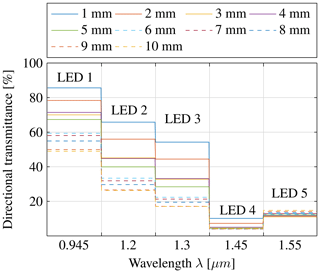
Figure 10Measured directional transmittance for increasing water film heights from 1 to 10 mm with white tile surface at a distance of 5 cm.
The following statements can be made by using the directional transmittance shown in Fig. 10. The discrete values of the transmittance at a water film height of 1 mm correspond approximately to those of the theory in Fig. 1. The transmittance is lowest at a wavelength of 1.45 µm. Subsequently, the transmittance increases for the wavelengths 1.55, 1.3 and 1.2 µm, and the highest is at 0.945 µm. A further statement refers to the resolution of the respective LEDs with increasing water film height. This is shown by the steps of the diagram with increasing water film height. The difference between the transmittances of two water film heights is approximately the same for the wavelengths 0.945, 1.2 and 1.3 µm. By considering the transmittance, those wavelengths are suitable for quantitative data for the water film height of 1 to 8 mm. At a wavelength of 1.45 µm, the transmittance remains unchanged from a water film height of 3 mm. The increase in intensity of LED 5 with a wavelength of 1.55 µm can be explained by the fact that the distance between sensor and surface of the water decreases with increasing water film height. Accordingly, the wavelengths 1.45 and 1.55 µm are suitable for a qualitative measurement of water film heights.
The investigation in Sect. 4.1 shows that the intensity decreases with increasing distance between sensor and ground. Therefore, the measurement was also performed with increasing water film height for a sensor distance of 10 and 15 cm. As a comparison, the transmittance at a water film height of 1 mm at different sensor distances on a white background is shown in the Fig. 11.
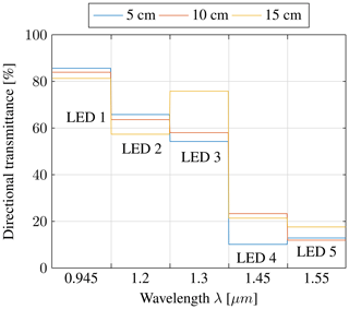
Figure 11Transmittance at a water film height of 1 mm for different distances with a white tile surface.
The comparison of the transmittances in Fig. 11 shows that the transmittance is different for various sensor distances. One reason for this is the solid angle of the respective LED, which rises with increasing distance. As a result, untraceable reflections and scattering occur at the background as well as at the water. Nevertheless, it can be seen from the figure that the degree of transmission provides information about the existence of water. At a sensor distance of 15 cm it is only possible to determine that water is available on the surface but not the water film height. Subsequently, the examination was also carried out for water film heights from 0 to 10 mm in 1 mm steps on a black surface at a sensor distance of 5 cm. The measured intensities are visualized in Fig. 12 with increasing water film height.
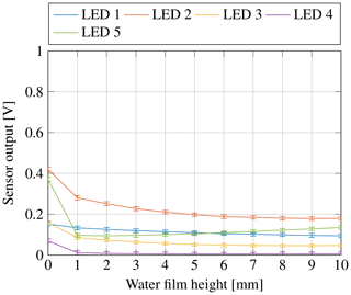
Figure 12Measurements of water film heights from 1 to 10 mm on a black tile surface at a distance of 5 cm.
Figure 12 shows that the intensity change for the shortest wavelength LED 1 is comparatively lower than for the other LEDs. Due to the intensity change with increasing water film height, only LED 1 shows a continuous decrease of intensity. The intensity of LED 5 decreases with the transition from dry to wet. As soon as the surface is wet, the intensity increases with increasing water film height. This is also caused by the increasing reflection percentage compared to the absorption percentage with increasing water film height. The intensity of the other LEDs decreases when water is present.
Figure 13 shows the transmittance for each wavelength with increasing water film height. These measurements are consistent with the theoretical transmission behaviour. For the LED 1, 2 and 3, the difference between two water film heights is approximately the same as for the white background. The LED 1 allows a quantitative indication of all water film heights. For the LED 2 and 3 it applies that from a water film height of 5 mm the transmittance does not give a clear indication about the water film height. The intensity of the LED 4 from a water film height of 1 mm is strongly absorbed. The intensity of LED 5 is more reflected than absorbed, which is the reason why higher water film heights can be inferred from the increasing transmittance. The light gets absorbed completely after 2 mm and the reflection dominates. The water film height can be determined by comparing the intensity of LED 5 with that of another LED. Two LEDs may be sufficient to determine the water film height.
4.3 Investigation of ice and water
The aim of this measurement was to verify the detection of ice by means of the theoretical approach. The water film height and the thickness of the ice layer on the white tile surface were 1 to 4 mm. The measurements were performed at a distance of 5 cm between sensor and surface of the white tile. In Fig. 14 the solid lines represent water, the dashed lines represent ice and the height of the medium is represented by the colour. As the solid lines in Fig. 14 show, the light at a wavelength of 1.55 µm is strongly absorbed by ice compared to water at all different layer heights. Thus, the classification of ice should be possible by comparing the transmittance at the different wavelengths.
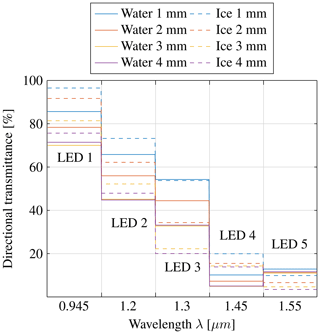
Figure 14Measured directional transmittance of water and ice at a distance of 5 cm with a layer height of 1 to 4 mm on a white tile surface.
In Fig. 14 it can be seen that the intensities of LED 1 with a wavelength at 0.945 µm and LED 2 with a wavelength at 1.2 µm are absorbed more by water than by ice at the same height. The intensity of LED 3 with the wavelength at 1.3 µm shows, for water and ice with a height of 1 mm, almost the same transmittance. At the layer heights from 2 to 4 mm, the light of LED 3 is absorbed more by water than by ice. The light of LED 4 with a wavelength at 1.45 µm is generally absorbed more by water than by ice at all different heights. As described above, the light of LED 5 with a wavelength at 1.55 µm is more absorbed by ice than by water at all different heights. Consequently, ice with a thickness of 1 mm absorbs more light at a wavelength of 1.55 µm than water with a water film height of 4 mm. The theoretical approach to the detection of ice includes the comparison of the transmittance at the last two wavelengths. Light at the wavelength of 1.45 µm is more absorbed by water than light at the wavelength of 1.55 µm. Ice, on the other hand, transmits light at the wavelength of 1.45 µm more efficiently and absorbs 1.55 µm more strongly. Other combinations such as LED 2 and LED 5 or LED 1 and LED 5 can also be used to distinguish between water and ice. Here, the transmittance of the light from LED 1 and LED 2 is higher like the transmittance of the light from LED 4 when ice is present instead of water. Consequently, a qualitative distinction can be made between water and ice by comparing these light intensities at different wavelengths. For this distinction two LED emitters are sufficient.
This work presented an infrared-based sensor system with one photodiode as the receiver and five different LEDs as the transmitter for contactless detection of wetness and ice on a surface. In the first part of this paper, a theoretical approach was used to determine the appropriate emitters and receiving diodes. Five LEDs were selected as transmitter diodes. A photodiode sensitive in the wavelength range from 0.9 to 1.7 µm was selected as the receiver. Subsequently, a measuring environment was created which reproducibly sprays a defined water film in steps of 1 mm onto a surface. This has a strain gage balance that measures the weight of the sprayed water to determine the water film height. In the next step, the measurements were carried out. With the first measurements, the influence of the brightness of the surface was investigated. The measurements were performed at a distance between sensor and surface of 5 to 15 cm in 1 cm steps. A white tile and a black tile were used as the surface. The measurements showed that the white surface reflects much more light back than the black surface. The intensity of the monochromatic lights decreases from 55 % to 72 % depending on the wavelength through the black surface. With the aid of the relative intensity, the inverse-square law of distance could be confirmed. The intensity decreases by 75 % when doubling the distance and is consequently only a quarter of the original intensity. Next, the measurements were performed with different water film heights from 1 to 10 mm at a distance of 5 cm between sensor and the white and the black tile. Furthermore, measurements were carried out at a distance of 5, 10 and 15 cm with a water film height of 1 mm with a white tile surface.The measurements with water on the surface showed that the sensor system has a similar course as the transmission spectrum of water. Here it was evident that a part of the light of LED 5 with 1.55 µm wavelength was absorbed by water, and a part was reflected back from the water surface. Due to the intensity increasing with the water film height, it is possible to measure the water film height with this sensor system. The investigations carried out with ice showed that ice can be detected qualitatively by comparing the transmittance at different wavelengths. The light with a wavelength of 0.945, 1.2 and 1.45 µm is more strongly absorbed by water than by ice. For light with a wavelength of 1.55 µm it is exactly the opposite. The light is absorbed more strongly by ice than by water. Here it was shown that ice with a thickness of 1 mm is more strongly absorbed than water with a water film height of 4 mm. Consequently, a distinction can be made between water and ice by comparing the transmittance at these wavelengths.
The underlying measurement data are not publicly available and can be requested from the authors if required.
KLK supervised the project and proofread the manuscript. LT developed the sensor system. JD and LT built the test bench and carried out the experiments. LT prepared the manuscript.
The authors declare that they have no conflict of interest.
This article is part of the special issue “Sensors and Measurement Systems 2019”. It is a result of the “Sensoren und Messsysteme 2019, 20. ITG-/GMA-Fachtagung”, Nuremberg, Germany, 25–26 June 2019.
This research has been supported by the German Federal Ministry for Economic Affairs and Energy (project: SEEROAD).
This paper was edited by Gerald Gerlach and reviewed by two anonymous referees.
Destatis – Federal Statistical Office Germany: Fachserie 8 Reihe 7 Verkehr Verkehrsunfälle, Federal Statistical Office Germany – Destatis, Wiesbaden, 2018. a
Döring, J., Tharmakularajah, L., Happel, J., and Krieger, K.-L.: A novel approach for road surface wetness detection with planar capacitive sensors, J. Sensors Sensor Syst., 8, 57–66, https://doi.org/10.5194/jsss-8-57-2019, 2019. a
Günzler, H. and Gremlich, H.-U.: IR-Spektroskopie: Eine Einführung, Wiley-VCH Verlag GmbH & Co. KGaA, Weinheim, Germany, https://doi.org/10.1002/9783527662852, 2003. a
Harten, U.: Physik, Springer-Lehrbuch, Springer, Berlin, Heidelberg, https://doi.org/10.1007/978-3-642-53854-4, 2014. a
Holzwarth, F. and Eichhorn, U.: Non-contact sensors for road conditions, Sensors Actuat. A: Phys., 37–38, 121–127, https://doi.org/10.1016/0924-4247(93)80023-A, 1993. a, b
Jonsson, P.: Remote sensor for winter road surface status detection, in: 2011 IEEE SENSORS, 28–31 October 2011, Limerick, Ireland, 1285–1288, https://doi.org/10.1109/ICSENS.2011.6127089, 2011. a
Klempau, F.: Untersuchungen zum Aufbau eines Reibwertvorhersagesystems im fahrenden Fahrzeug, Dissertation, Universität Darmstadt, Darmstadt, 2003. a, b
Kurata, R., Watanabe, H., Tohno, M., Ishii, T., and Oouchi, H.: Evaluation of the detection characteristics of road sensors under poor-visibility conditions, in: IEEE Intelligent Vehicles Symposium, 14–17 June 2004, Parma, Italy, 538–543, https://doi.org/10.1109/IVS.2004.1336441, 2004. a
Schrey, O., Brockherde, W., and Hosticka, B.: Distance sensor and method for distance detection, uS 20060214121 A1, United States Patent Application Publication, Oakland, USA, 2005. a
Tharmakularajah, L., Döring, J., and Krieger, K.-L.: Infrared-based determination of the type and condition of the road surface, in: 19. Internationales Stuttgarter Symposium, Internationales Stuttgarter Symposium Automobil- und Motorentechnik, 19–20 March 2019, Stuttgart, https://doi.org/10.1007/978-3-658-25939-6_31, 2019. a
Warren, S. G.: Optical constants of ice from the ultraviolet to the microwave, Appl. Optics, 23, 1206–1225, https://doi.org/10.1364/AO.23.001206, 1984. a


