the Creative Commons Attribution 4.0 License.
the Creative Commons Attribution 4.0 License.
 | 12 Mar 2021
Creep adjustment of strain gauges based on granular NiCr-carbon thin films
Maximilian Mathis
Dennis Vollberg
Matthäus Langosch
Dirk Göttel
Angela Lellig
Günter Schultes
An important property of high-precision mechanical sensors such as force transducers or torque sensors is the so-called creep error. It is defined as the signal deviation over time at a constant load. Since this signal deviation results in a reduced accuracy of the sensor, it is beneficial to minimize the creep error. Many of these sensors consist of a metallic spring element and strain gauges. In order to realize a sensor with a creep error of almost zero, it is necessary to compensate for the creep behavior of the metallic spring element. This can be achieved by creep adjustment of the used strain gauges. Unlike standard metal foil strain gauges with a gauge factor of 2, a type of strain gauges based on sputter-deposited NiCr-carbon thin films on polymer substrates offers the advantage of an improved gauge factor of about 10. However, for this type of strain gauge, creep adjustment by customary methods is not possible. In order to remedy this disadvantage, a thorough creep analysis is carried out. Five major influences on the creep error of force transducers equipped with NiCr-carbon thin-film strain gauges are examined, namely, the material creep of the metallic spring element (1), the creep (relaxation) of the polymer substrate (2), the composition of the thin film (3), the strain transfer to the thin film (4), and the kind of strain field on the surface of the transducer (5). Consequently, we present two applicable methods for creep adjustment of NiCr-carbon thin- film strain gauges. The first method addresses the intrinsic creep behavior of the thin film by a modification of the film composition. With increasing Cr content (at the expense of Ni, the intrinsic negative creep error can be shifted towards zero. The second method is not based on the thin film itself but rather on a modification of the strain transfer from the polyimide carrier to the thin film. This is achieved by controlled cutting of well-defined deep trenches into the polymer substrate via a picosecond laser.
- Article
(2072 KB) - Full-text XML
- BibTeX
- EndNote


Many sensor types to determine mechanical quantities like force, pressure or torque are based on strain gauges (SGs). These sensors usually consist of a metallic spring element and metal foil SGs which are connected to a Wheatstone bridge. An applied load (force, pressure, torque) causes elastic deformations in certain areas and surfaces of the spring element. These tensile and compressive strain fields lead to electric resistance changes of the attached SGs, and as a result, the sensor signal increases or decreases, respectively. The constant of proportionality between relative resistance change and strain is called gauge factor (k). Common metal foil SGs are manufactured by laminating an electrically insulating polymer foil (polyimide or polyether ether ketone, PEEK) with a thickness of around 20 µm onto a conductive foil (resistor material) with a thickness of approximately 2–5 µm. The metal foil is then shaped into a grid by means of photolithography and etching (Kieffer, 2018). For resistor materials like NiCr, CuNi or PtW alloys, the gauge factors range between 2 and 4 (Keil, 2017). An important characteristic value of the mentioned strain-gauge-based sensor types is the creep error, meaning reversible signal deviations over time at a constant load. For example, a load cell with a positive creep error would show an increase in load over time, although the applied load was not changed. Since the accuracy of a sensor is reduced by the creep error, it is favorable to minimize it. The creep of a sensor mainly consists of two contributions: creep of the spring element and creep of the SGs (Kieffer, 2018). A constant load applied to the spring element for a certain period of time results in an increase of the elastic deformation over time. Thus, an increasing sensor signal would be measured and mistakenly interpreted as a load change. The magnitude and time constant of the strain increase are strongly dependent on the material, temperature and mechanical stress level of the spring element (Robinson et al., 2003). The second creep contribution, which is induced by the SGs, is very dependent on the SG type. The creep of metal foil SGs, for example, is caused by stress relaxation. When a metal foil SG is exposed to constant strain for a certain period of time, the elastic force of the metal grid causes shear stress in the transition zone of grid and carrier, mainly underneath the reverse loops of the grid. The emerging stress leads to relaxation of the polymer material beneath the metal grid (polymer foil and adhesives); hence, the metal grid draws back (Keil, 2017). This results in a decreasing sensor signal. However, the creep behavior of metal foil SGs can be well controlled by several mechanisms based on modifications of the grid design or bridge circuit (Burfeindt et al., 2000; Kieffer et al., 2006; Kreuzer, 2006; Zandman et al., 2012). Optimally, the positive creep of the spring element and the negative creep of the strain gauge would compensate each other over the entire operating temperature range and would result in a net zero creep signal.
A different kind of SG is produced by sputter deposition of a piezoresistive thin film with a thickness between 100 nm and 1 µm on a polymer substrate, followed by structuring of a resistor geometry. The creep error of these thin-film SGs is dependent on relaxation of the polymer substrate (Nishikawa et al., 1985) and also on an additional creep contribution from the thin film material itself (intrinsic creep). In the case of metallic thin films, a sandwich structure of two materials with different creep behaviors allows for adjustment of the SG creep contribution; subsequently, it enables creep compensation of transducers (Grange et al., 1995). Unlike pure metallic thin films, granular thin films based on metal–carbon develop gauge factors up to 30 (Schultes et al., 2018). Consequently, transducers equipped with foil strain gauges of this type are by far more sensitive. The freedom to design load cells is thus enhanced significantly; for example, the design of stiffer spring elements with increased overload capability is possible. However, for metal–carbon thin-film SGs, the creep behavior is more complex and creep adjustment by customary methods is not possible. This paper presents an in-depth study of the major influence factors on the creep behavior of force transducers with granular NiCr−C thin-film strain gauges, such as material creep of the spring element, the relaxation of polymer carrier, the composition of the thin film, the strain transfer to the thin film and the strain field on the spring element (uniaxial or biaxial). As a result, two applicable methods for creep adjustment of NiCr−C thin-film strain gauges are highlighted. Since it is hardly possible to separate the creep contribution of the polymer carrier and the strain gauge adhesive, we kept the influence of the adhesive constant by usage of the same adhesive type and application routine in all our experiments.
Granular thin-film SGs were manufactured by reactive sputter deposition of a NiCr−C thin film with a thickness of approximately 150 nm onto a polyimide foil with a thickness of 50 µm, according to Vollberg et al. (2015). For this purpose, a foil sputtering system WEB400sp (Leybold Optics) with argon (99.999 % purity) as process gas and ethylene (99.95 % purity) as precursor gas was used. The sputtered thin films consist of granular NiCr−C, whereby the mass ratio of Ni to Cr was set to 50:50 (Ni50Cr50), 80:20 (Ni80Cr20) or 90:10 (Ni90Cr10) by applying different targets. For the three thin film types, the ratio of ethylene to argon flow was set to obtain a temperature coefficient of resistance (TCR) in the range of 0 to −200 ppm K−1 while maintaining a high gauge factor. As substrates, two polyimide foils with different mechanical properties were chosen. In the following, the foil Upilex-S (UBE Industries) is designated as type A and the foil Kapton EN (DuPont) is designated as type B. Type A has a higher tensile modulus, a lower Poisson's ratio and a much lower surface roughness than type B. The mechanical properties of both types according to the data sheets and manufacturer information are given in Table 1.
Table 1Mechanical properties of polyimide type A (Upilex-S, UBE Industries) and type B (Kapton EN, DuPont) according to the data sheets and manufacturer information (status year 2018).
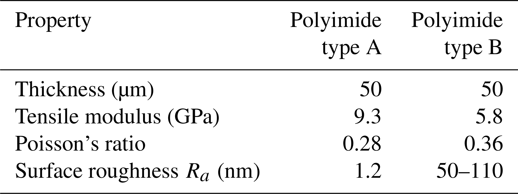
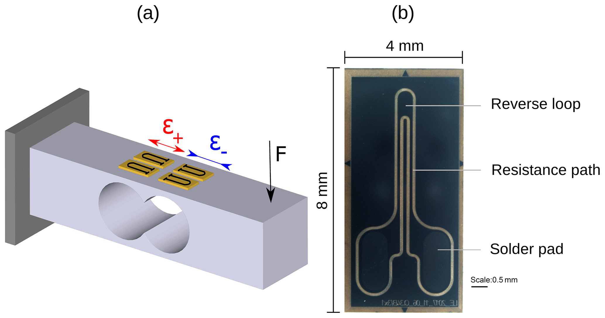
Figure 1(a) Model of a force transducer consisting of a bending beam and four SGs. An applied force F causes areas of tensile (ϵ+) and compressive (ϵ−) strain where the SGs are attached. (b) Microscopic image (front view, mirrored) of a strain gauge produced for this study. The linear structure consists of two straight paths, a reverse loop and two solder pads.
In order to create the necessary resistor geometry of the SGs, the thin film on top of the polyimide foil was structured by means of a Nd:YVO4 laser system (3D-Micromac) with a wavelength of 355 nm and a pulse duration <15 ps. This laser type allows for controlled ablation of the thin film (Langosch et al., 2015) as well as the polyimide carrier (Gomez et al., 2005; Adhi et al., 2004), so the creation of electrically insulating separation trenches is possible. In this way, the generation of resistance paths as shown in Fig. 1b was realized. The depicted structure consists of two straight paths, a reverse loop and two solder pads. After structuring, the SGs were cleaned with isopropanol in an ultrasonic bath, annealed and provided with solder pads of a solderable, sputter-deposited thin film. This thin film consists of WTi, Ni and Au and has a thickness of approximately 200 nm. Subsequently, the SGs were attached to spring elements using the strain gauge glue M-Bond 610 (Vishay Precision Group) and were connected to a Wheatstone full bridge by soldering. As spring elements, bending-beam load cells as well as tension and compression force transducers of an aluminum alloy were used. The bending beams (depicted in Fig. 1a) have a nominal load of 18 kg with an uniaxial strain field of approximately ± 1 ‰ at the gauge positions. In contrast, the tension and compression force transducers (depicted in Fig. 2) have a nominal load of 100 kg with a biaxial strain field. The tensile strain ϵ+ is 0.45 ‰ and the compressive strain ϵ− is −0.4 ‰ at the gauge positions. To characterize the material creep of the bending beam itself, the time-dependent displacement under constant load was measured. In our case, this was realized by means of a capacitive displacement sensor CSH05 and a capaNCDT 6220 multichannel measurement system (Micro-Epsilon Messtechnik). The bridge signals of the sensors were characterized by means of dead-load machines, a precision amplifier DMP 39-1 (HBM) and a measuring module Q.brixx A107 (Gantner Instruments). The creep and creep recovery were measured first without load and then with the nominal load applied for 15 min, followed again without load for the recovery. The time to load and unload the sensors was approximately 1 min for all measurements. A typical signal curve for a sensor consisting of a bending beam with attached Ni90Cr10−C thin-film SGs is illustrated in Fig. 3a. The signal deviations are referred to the full-scale (FS) sensor signal and represent the creep (loaded state) and creep recovery (unloaded state) error, as shown in Fig. 3b. The offset between the end of the creep curve and the start of the creep recovery curve is caused by the time to unload the sensor. The difference between the creep recovery error at 15 min and zero is called zero point return (see Fig. 3b). The focus of the investigation is put on the creep.
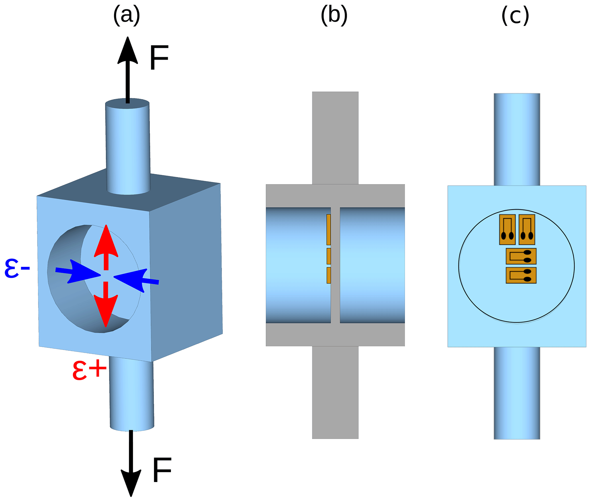
Figure 2(a) Model of a tension and compression force transducer with applied force “F” and resulting compressive (ϵ−) and tensile (ϵ+) strain on the membrane surface. (b) Sectional view of the transducer shows the position and thickness of the membrane and the attached strain gauges. (c) Front view of the force transducer with positions of the strain gauges (Mathis et al., 2020).
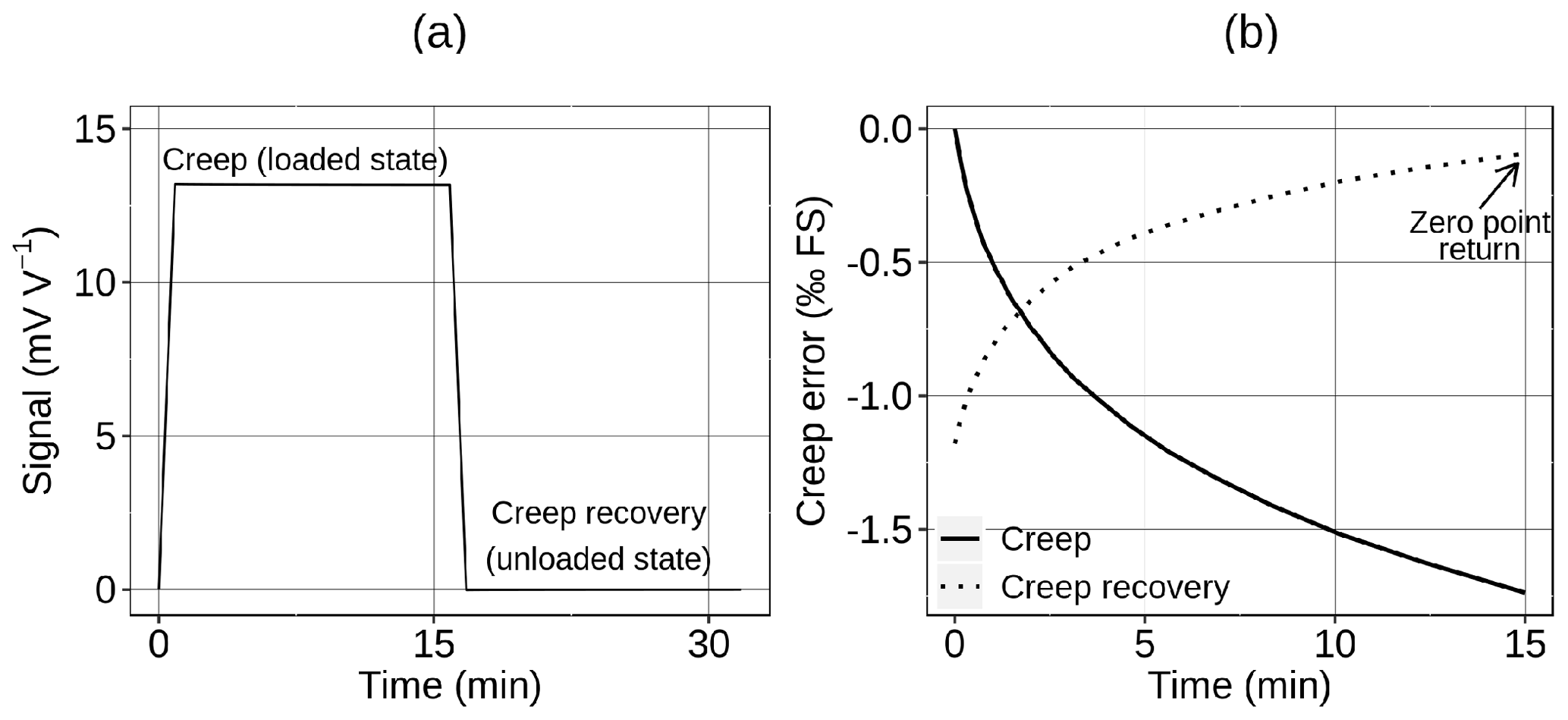
Figure 3(a) The typical signal curve of a bending beam with a bridge circuit of Ni90Cr10−C thin-film SGs in a creep measurement consisting of the creep (loaded state) and the creep recovery (unloaded state). (b) The creep, the creep recovery and the zero point return error are referred to the full-scale (FS) signal. The creep and the creep recovery are both measured for 15 min; for comparison purposes, both phases are plotted with the same timescale.
Like other thin films, granular metal–carbon films show an intrinsic creep behavior. Therefore, one method to adjust the creep error of the SGs is based on modification of the thin film composition. For instance, the intrinsic creep of Ni−C thin films can be dramatically reduced by substituting Ni with NiCr (Cerino et al., 2015; Vollberg et al., 2015); however, this is accompanied with a loss of sensitivity. A substitution of Ni by NiCr with a mass ratio of Ni to Cr of 90:10 reduces the gauge factor from around 30 to approximately 10. By further increasing the Cr content of the thin film, the intrinsic creep is reduced even more (Cerino et al., 2015), but this also results in further reduction of the gauge factor by up to 30 %.
The second method for creep adjustment is based on a modification of strain transfer in transverse direction with a decrease of the gauge factor by 15 % at most. Strain gauges are not only sensitive to strain acting in direction of the electrical current (longitudinal direction) but also to strain in perpendicular (transverse) direction. For metal foil SGs, the transverse gauge factor (kT) is usually less than 1 % of the longitudinal gauge factor (kL). However, this is not the case for strain gauges based on granular metal–carbon films. For NiCr−C films, the ratio is typically around 50 %. The comparably high transverse gauge factor is an intrinsic property of granular thin films and is caused by local transverse current paths due to the particle arrangement of the film (Schwebke et al., 2018). A modification of strain transfer allows us to reduce the transverse gauge factor from 50 % to about 1 % of the longitudinal gauge factor (Langosch and Vollberg, 2017; Mathis et al., 2020) in the case of a SG layout without reverse loops. For a SG layout with one reverse loop, the ratio can be reduced to around 5 %. A further reduction for this layout was not carried out, so far. In order to create the necessary resistance paths of the SGs as shown by the model in Fig. 4, separation trenches are cut into the polyimide carrier foil by means of a picosecond laser, whereby the depth and width of the trenches can be controlled via the laser parameters. Depending on the width (w) and height (h) of the remaining polyimide paths, the transfer of transverse strain (ϵT) and thus the transverse gauge factor can be adjusted. This method does not only affect the transverse gauge factor but the creep behavior of the SGs as well. Longitudinal strain (with or without transverse strain) which is applied to such a SG results in transverse contraction of its resistance paths. This inhibits relaxation of the polyimide in transverse direction, and consequently the creep error is reduced. Due to the transverse contraction of the resistance paths, the effective longitudinal gauge factor is also reduced, depending on the Poisson's ratio (ν) of the substrate foil as well as the longitudinal and transverse gauge factor of the thin film. According to Eq. (1) (Mathis et al., 2020), for a Poisson's ratio of 0.3 and a ratio of 50 %, the reduced gauge factor kL, red equals 85 % of the initial gauge factor kL.
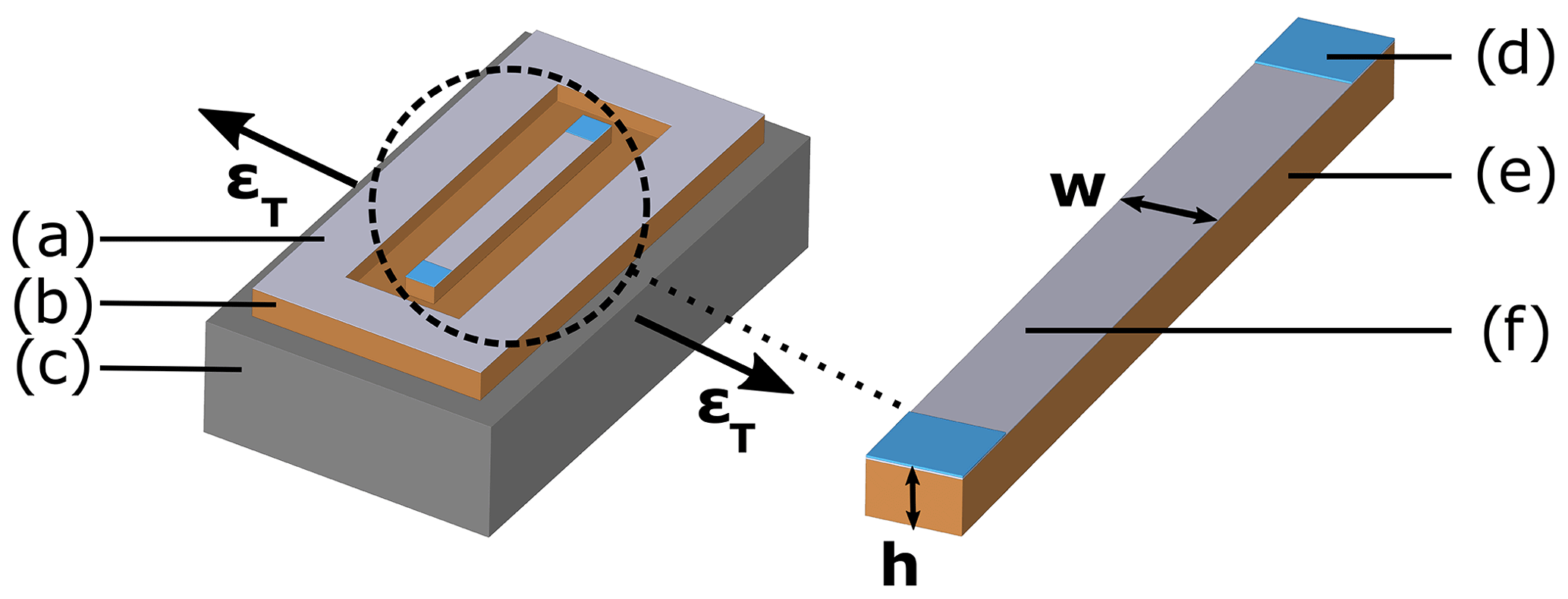
Figure 4Model of a thin-film SG (without reverse loops) which is attached to a metal component. The geometry of the polyimide path allows us to influence the strain transfer from the metal component to the active thin film: (a) granular thin film, (b) polyimide carrier, (c) transversally strained metal component, (d) solder pad, (e) polyimide path with height h and width w, and (f) active granular thin-film element (Mathis et al., 2020).
In this paper, both creep adjustment methods are compared by means of creep measurements on force transducers with corresponding NiCr−C thin-film strain gauges. Furthermore, influencing factors on the creep such as the creep contribution of the spring element, the type of polymer carrier and the strain field on the spring element (uniaxial or biaxial) are investigated.
4.1 Material creep contribution of the bending beam
First, the creep contribution of the spring element itself is examined, because it is fundamental to the creep problem. Therefore, the time-dependent displacement of a bending beam near the point of force application was determined at constant load. The relative change in displacement after 15 min at nominal load (strain of ± 1 ‰) is equal to the material creep, as shown in Fig. 5 for an aluminum-based alloy as transducer material in the temperature range from 10 to 85 ∘C. As expected, the creep error of the bending beam is positive and increases with temperature. From 10 to 50 ∘C, the creep rises only slowly; however, at 85 ∘C the creep error is almost 1 ‰ FS for the aluminum alloy. For a complete force sensor, the positive creep of the spring element is superimposed by other creep effects which are presented hereinafter.
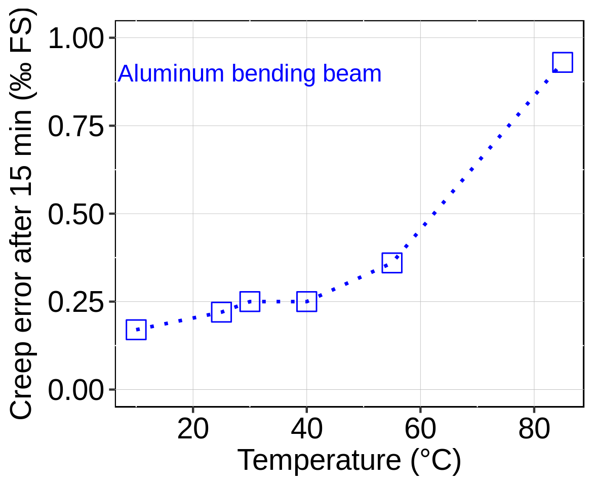
Figure 5Material creep error after 15 min of an aluminum bending beam measured by means of a capacitive displacement sensor.
4.2 Creep contribution of the polymer substrate
In order to determine the impact of the carrier material on creep behavior of the SGs, the two different polyimide foils, type A and B, are compared. Thereby, all other parameters like resistor geometry or adhesive temperature were kept the same. A Ni90Cr10−C thin film was deposited on both substrates in a single sputtering process and subsequently SGs according to the depicted procedure were manufactured and attached to bending-beam load cells (see Fig. 1a) of the aluminum alloy. The polymer type affects the sensitivity since the average sensor signal at nominal load is higher for polyimide type B (13.3 mV V−1 at 30 ∘C) than for type A (12.2 mV V−1 at 30 ∘C). The reason for this might be a slightly different thin-film structure due to the different surface roughnesses of the substrates. The dissimilar tensile moduli might also play a role. The creep error of several load cells was measured at 30, 40, 55 and 85 ∘C for both types. The results are illustrated in Fig. 6. Noticeably, the creep error of the load cells is now negative and greatly dependent on the SG carrier foil. Polyimide of type B develops a stronger response, creeping about 1 ‰ FS more negative than type A. Moreover, the standard deviation for type B (0.21 ‰ FS) is multiple times higher than for type A (0.04 ‰ FS) at 30 ∘C, probably due to the higher surface roughness of type B. The deviations of the measured creep errors at each temperature are certainly also caused by the manual fabrication (gluing, soldering) of the sensor specimens.
The creep error becomes more negative with increasing temperature, which is independent of the used polyimide foil. The difference in creep between the two substrates is probably caused by different stress relaxation behaviors of the foils. This is very likely considering the differences in tensile modulus and Poisson's ratio. The zero point return after creep recovery also shows a slight dependency on the polymer substrate. Polyimide type A shows an average zero point return of −0.05 ‰ FS. In contrast, the average zero point return of type B is more negative with a value of −0.1 ‰ FS.
This experiment clearly demonstrates the influence of the carrier substrate on the creep error of NiCr−C thin-film strain gauges.
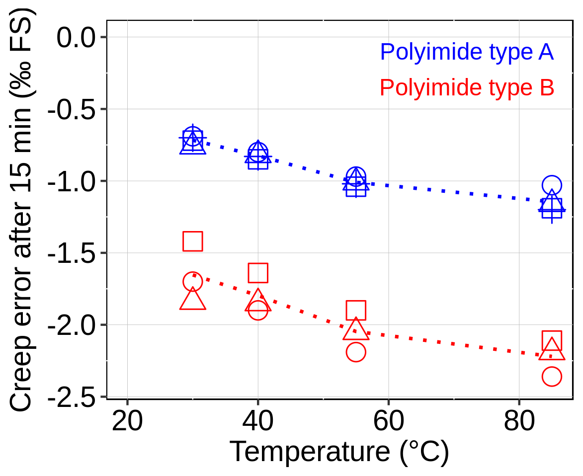
Figure 6Creep error after 15 min of aluminum bending beams with attached Ni90Cr10−C thin-film SGs, which is plotted versus temperature. The SGs are based on two different carrier substrates: polyimide type A (blue) and type B (red). Every marker symbol represents a sensor specimen; the dotted lines connect the average values (not shown here).
4.3 Creep adjustment by modification of the Cr content of the thin film
In the following, the influence on the creep error by a modification of the Cr content of NiCr−C thin films is examined. For this purpose, SGs based on polyimide type A and three different NiCr−C film variations, namely, Ni50Cr50−C, Ni80Cr20−C and Ni90Cr10−C, were produced and applied on aluminum bending beams. The resistor geometry and application routine was kept the same for all three variations. Figure 7 sums up the results of the performed creep measurements. Apparently, the two load cells with SGs made of Ni50Cr50−C thin film reveal a different creep behavior than the beams with SGs of Ni80Cr20−C and Ni90Cr10−C film, especially at higher temperatures. The higher content of Cr reduces the intrinsic creep of the thin film; thus, the creep of the load cell is shifted more towards the positive creep of the spring element. Hence, the most negative creep error of load cells with SGs of Ni50Cr50−C is only around −0.5 ‰ FS. The difference in creep behavior between Ni80Cr20−C and Ni90Cr10−C is only marginal, since the difference in Cr content is small as well. The Cr content of the thin film does not only influence the creep behavior but also the strain sensitivity of the sensor. For SGs of Ni90Cr10−C and Ni80Cr20−C thin film, the average sensor signal at nominal load and 30 ∘C is 12.2 and 12.1 mV V−1, respectively. For Ni50Cr50−C on the contrary, the signal is reduced to 8.7 mV V−1, a decrease of almost 30 %. The zero point return (after creep recovery) also seems to be influenced by the change in Cr content. The SG version with Ni90Cr10−C shows an average zero point return of −0.05 ‰ FS. For Ni80Cr20−C as thin film, the zero point return is more negative with an average value of −0.09 ‰ FS. Eventually, the average zero point return of SGs with Ni50Cr50−C as thin film is only −0.01 ‰ FS.
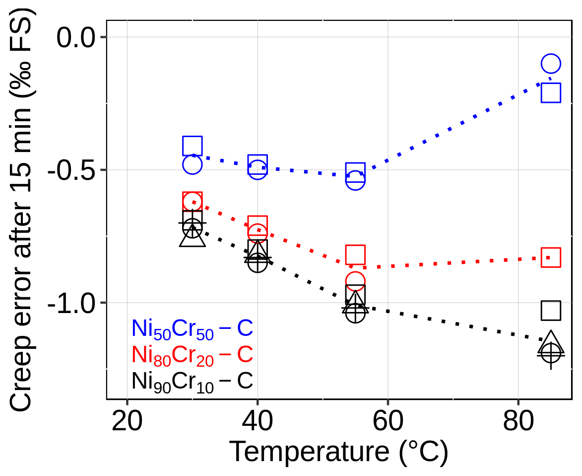
Figure 7Creep error after 15 min of aluminum bending beams with attached thin-film SGs of three different film compositions, which is plotted versus temperature. The films Ni50Cr50−C, Ni80Cr20−C and Ni90Cr10−C were deposited on polyimide type A. Every marker symbol represents a sensor specimen; the dotted lines connect the average values (not shown here).
4.4 Creep adjustment by modification of the strain transfer
The ratio of Ni90Cr10−C SGs was adjusted to 50 % as well as 10 % for both substrates, polyimide type A and B. This was achieved by setting the height of the polyimide paths to 2.5 µm (50 %) and 30 µm (10 %), respectively. The path width was 100 µm in both cases. Aluminum bending beams were subsequently equipped with these SGs and characterized in the temperature range from 30 to 85 ∘C. The results of the creep measurements for polyimide type A and B are shown in Fig. 8a and b, respectively. For both carrier materials, the temperature-dependent absolute creep error is clearly reduced using the SG variation with decreased transverse strain sensitivity. In the case of polyimide type A, the amount of creep reduction is 0.5 ‰ FS at 30 ∘C and even 0.8 ‰ FS at 85 ∘C. As a consequence, the absolute creep error is less than 0.5 ‰ FS in the temperature range. The amount of creep reduction in the case of polyimide type B is even 1.4 ‰ FS for a decrease of from 50 % to 10 %. This can be observed for the whole, tested temperature range. The fact that the amount of creep error reduction is so different for both polyimide types might be based on the distinct (temperature-dependent) stress relaxation behaviors of the two carrier materials. Polyimide type B seems to exhibit greater stress relaxation than type A, which leads to a more negative creep error of type B. The forced transverse contraction of the polyimide paths due to the modification of strain transfer inhibits this stress relaxation and consequently the induced creep, too. Thus, for polyimide type B a larger reduction of the creep error can be observed. As predicted, the sensitivity is reduced for the SGs with the reduced creep error. In the case of polyimide type A, the sensitivity at 30 ∘C is reduced from 12.2 to 10.8 mV V−1, a decrease by 11.5 %. For type B, a decrease in sensitivity by 13.5 %, from 13.3 to 11.5 mV V−1, could be observed. The difference in sensitivity loss can be explained by the different Poisson's ratios of the foils. A higher Poisson's ratio results in more transverse contraction of the paths and consequently a greater loss of sensitivity. A further improvement due to the reduced transverse sensitivity of the SGs is a better zero point return. This is the case for both polyimide types. For type A, the average zero point return is shifted from −0.05 ‰ FS to 0.01 ‰ FS. For type B, the value is reduced from −0.10 ‰ FS to −0.02 ‰ FS.
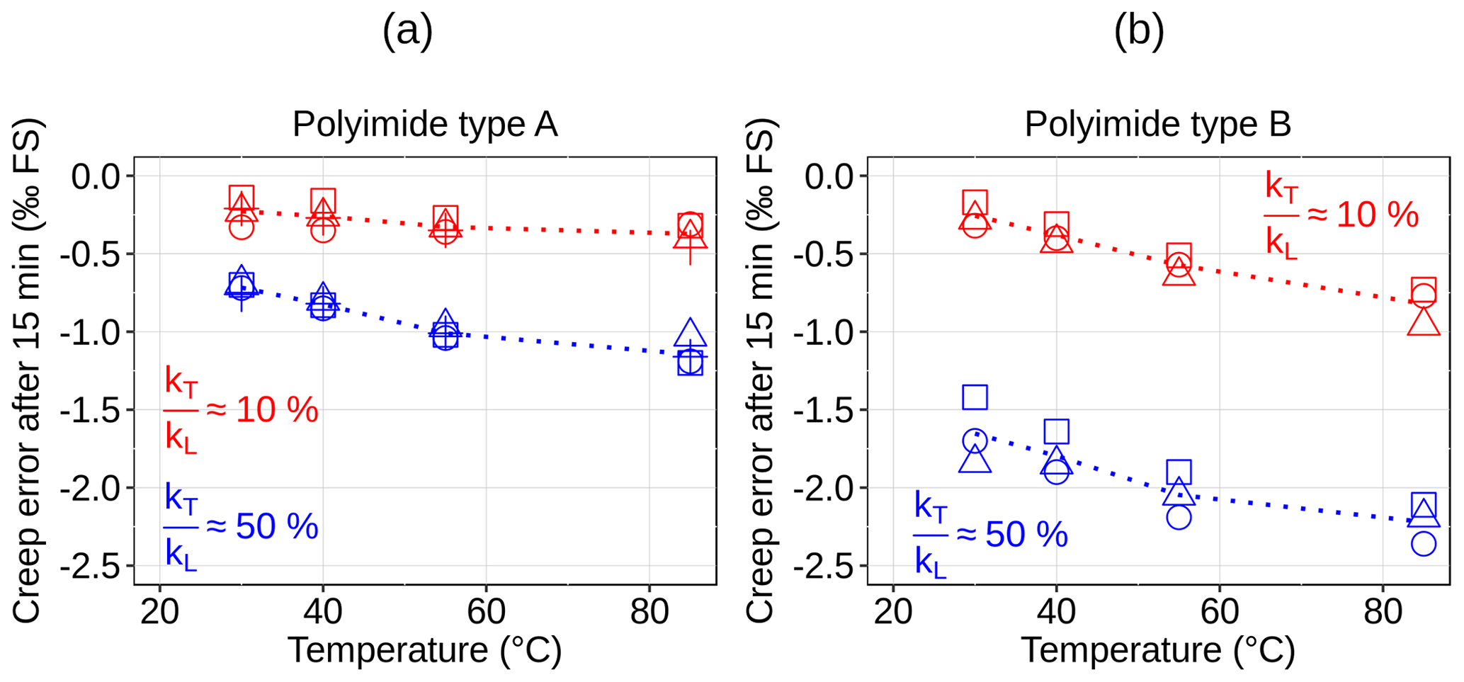
Figure 8Creep error after 15 min of aluminum bending beams with attached Ni90Cr10−C thin-film SGs depending on the ratio . The SGs are based on (a) polyimide type A and (b) polyimide type B. Every marker symbol represents a sensor specimen; the dotted lines connect the average values (not shown here).
4.5 Influence of the strain field
A striking feature of sensors equipped with NiCr−C thin-film SGs seems to be a more or less negative creep error. However, this is due to the fact that so far only force transducers with uniaxial strain fields were considered. The more complex strain field of tension and compression force transducers, similar to the model shown in Fig. 2, is biaxial with tensile strain ϵ+ of 0.45 ‰ and compressive strain ϵ− of −0.4 ‰ in perpendicular directions. Transducers of this kind, equipped with NiCr−C thin-film strain gauges, show a very different creep behavior. Two Ni90Cr10−C SG variations with ratios of 50 % and 5 %, both based on polyimide type A, were applied on tension and compression force transducers made of aluminum. For the SG variation with a ratio of 50 %, the height of the polyimide paths was set to 2.5 µm and the width to 100 µm. The paths of the improved SGs with a ratio of 5 % had a height of 18 µm and a width of 50 µm. Consequently, the sensors were characterized at temperatures of 10, 30, 50 and 70 ∘C. Figure 9 reveals a very strong positive creep error for SGs with a ratio of 50 %. The error is around 3.5 ‰ FS at 30 ∘C and decreases slightly for increasing temperatures; however, at 70,∘C the error increases further to more than 5 ‰ FS. The usage of SGs with a strongly reduced ratio of 5 % shifts the error towards zero. Nevertheless, the creep error increases with increasing temperature and reaches a value of about 3 ‰ FS at 70 ∘C. The usage of SGs with a reduced transverse gauge factor, applied on the biaxial strain field of tension and compression force transducers results in a nearly doubled sensitivity. Due to the reduced transverse gauge factor and despite the reduced longitudinal gauge factor, the sensitivity at 30 ∘C is increased from 2.2 to 4.1 mV V−1. The error of zero point return after creep recovery for this transducer type is much higher than for the bending-beam transducer, especially at 70 ∘C. Here, the average error is 1.75 ‰ FS in the case of a ratio of 50 %. For a ratio of 5 %, the zero point return is reduced to 0.95 ‰ FS. Between 10 and 50 ∘C, the average error of zero point return is 0.92 ‰ FS in the case of SGs with a ratio of 50 %. For a reduced ratio of 5 %, the zero point return is only 0.22 ‰ FS.
The result of this investigation shows that the strongly positive creep error of NiCr−C-based SGs, applied on biaxial strain fields, can be significantly decreased if the ratio is reduced. Moreover, it results in a nearly doubled sensitivity of the transducer.
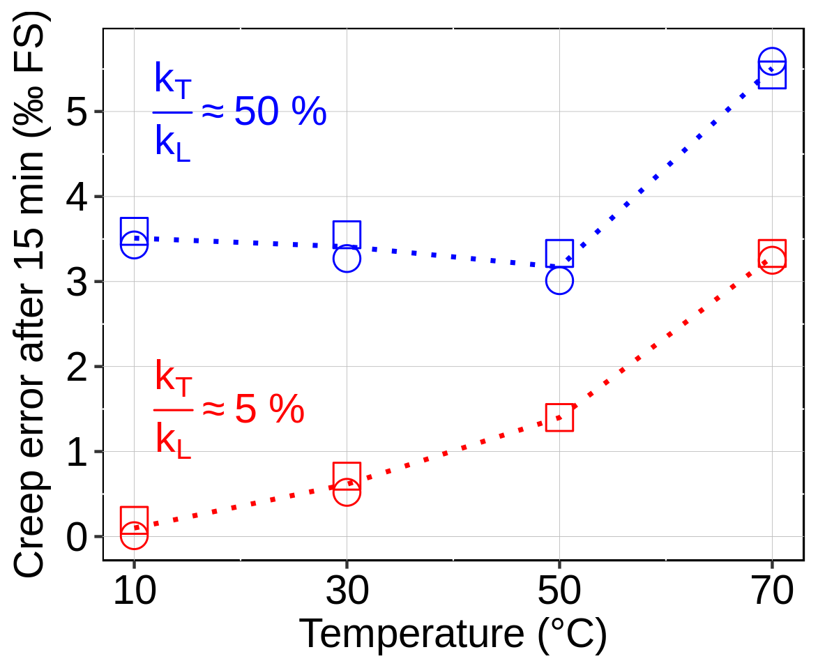
Figure 9Creep error after 15 min of aluminum tension and compression force transducers with attached Ni90Cr10−C thin-film SGs depending on the ratio . The SGs are based on polyimide type A. Every marker symbol represents a sensor specimen; the dotted lines connect the average values (not shown here).
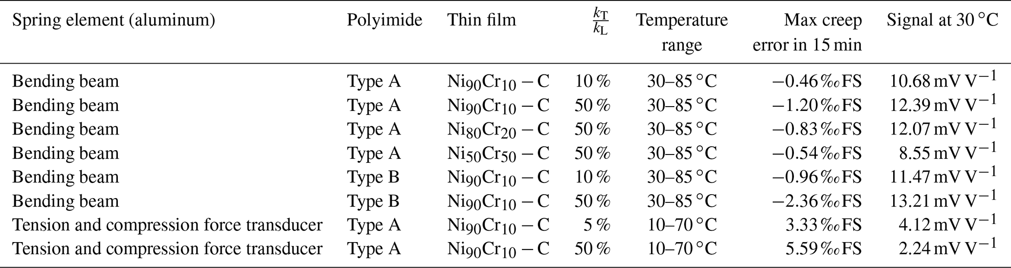
Table 2Overview of examined force transducers, their maximum measured creep errors in the temperature range and the corresponding sensor signals at 30 ∘C. The force transducers consist of a spring element and a Wheatstone bridge of four strain gauges. The strain gauges are categorized with respect to the used polyimide (polymer substrate), thin film, and ratio of transverse and longitudinal gauge factor .
4.6 Synopsis of results
The measured maximum creep errors and corresponding signals of the different force transducer configurations are summarized in Table 2. The configuration is categorized by the used spring element type as well as the polyimide, thin film, and ratio of transverse and longitudinal gauge factor of the applied strain gauges.
Figure 10 illustrates the improvements concerning creep adjustment of the SGs due to the selection of the carrier substrate and the modification of strain transfer. The raw creep of the aluminum spring element (bending beam), which is plotted over time in dotted red lines for different temperatures is superimposed by the creep of the SGs. A strong negative creep is developed by applying SGs of Ni90Cr10−C with its characteristic transverse strain sensitivity of 50 % on polyimide of type B, which is plotted in blue dashed lines. The resulting creep error of such sensors is very temperature dependent at values around −2 ‰ FS, which means too much overcompensation of the raw signal. Optimized sensors which are equipped with strain gauges of Ni90Cr10−C and strongly reduced transverse sensitivity ( 10 %) on polyimide type A are plotted with solid black lines. Their creep error is significantly reduced to approximately −0.3 ‰ FS with less temperature influence.
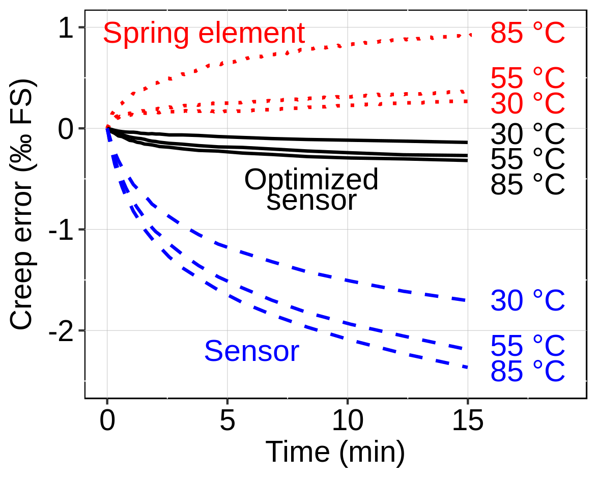
Figure 10Time-dependent creep error of a raw bending-beam-type spring element (dotted red lines), a sensor equipped with strain gauges of Ni90Cr10−C on polyimide type B (blue dashed lines) with regular transverse sensitivity ( 50 %) and an optimized sensor equipped with strain gauges of Ni90Cr10−C and strongly reduced transverse sensitivity ( 10 %) on polyimide type A (black solid lines) for three different temperatures.
Strain gauges based on granular NiCr−C thin films offer the advantage of higher sensor signals, which allow for enhanced freedom of design. In order to compensate the creep behavior of the metallic spring elements of force transducers, it is necessary to adjust the creep behavior of the strain gauges. Thus, five main influence factors on the creep behavior of force transducers with NiCr−C thin-film strain gauges are analyzed and presented. The creep error of such force transducers is dependent on the creep behavior of the spring element itself (1), the relaxation of the polymer substrate (2), the intrinsic creep of the thin film (3), the strain transfer to the thin film (4), and the kind of strain field as well (5). Consequently, we present two applicable methods for creep adjustment of NiCr−C thin-film strain gauges. The first method is based on a modification of the thin-film composition, which is realized by altering the mass ratio of Ni to Cr of the film. The creep error of aluminum load cells can be shifted by up to 1 ‰ FS for an increase of the Cr content from 10 % to 50 %. A trade-off of this approach is the decrease of the sensitivity by up to 30 %. Another approach is used for the second method of creep adjustment; it targets the strain transfer from the polyimide carrier to the thin film. Controlled laser cutting of well-defined deep trenches allows for the adjustment of the strain transfer perpendicular to the measurement direction of the strain gauges. This enables an adjustment of the creep contribution caused by relaxation of the polymer in combination with the transverse sensitivity of the thin film. With this approach, the creep error of bending beams equipped with NiCr−C strain gauges was adjusted to less than 0.5 ‰ FS (in 15 min) between 30 and 85 ∘C. Even though the method causes a slight decrease of the longitudinal gauge factor by up to 15 %, it allows us to reduce the sensor creep for strain gauges based on different types of polyimide carrier foils regardless of the strain field (uniaxial and biaxial). For other polymer carrier materials, creep adjustment by means of this approach should also be possible. Although the method was only proven for NiCr−C thin films, it is also highly likely that the results are transferable to other granular thin films with a comparatively high transverse gauge factor, which should be proven in further investigations.
The underlying data are available from https://doi.org/10.6084/m9.figshare.12941999.v1 (Mathis, 2020).
MM was responsible for the investigation, methodology, visualization and writing the original draft of the paper. DV and ML contributed to the conceptualization and reviewing and editing the paper. DG was responsible for the validation. AL carried out project administration. GS was responsible for supervision and reviewing and editing the paper.
The authors declare that they have no conflict of interest.
This research has been supported by the German Federal Ministry for Economic Affairs and Energy (grant no. 49VF170017, INNO-KOM).
This paper was edited by Ulrich Schmid and reviewed by three anonymous referees.
Adhi, K. P., Owings, R. L., Railkar, T. A., Brown, W., and Malshe, A.: Chemical modifications in femtosecond ultraviolet (248 nm) excimer laser radiation-processed polyimide, Appl. Surf. Sci., 225, 324–331, 2004. a
Burfeindt, H., Gerlach, H.-J., and Will, R.: Foil strain gauge for a measuring transducer, Patent No. EP 1 033 561 B1, Hottinger Messtechnik Baldwin, Germany, 2000. a
Cerino, M., Göttel, D., Probst, A.-C., and Schultes, G.: Schichtwiderstand mit einem kohlenstoffhaltigen Widerstandsmaterial und Verfahren zu dessen Herstellung, Patent No. DE 10 2015 006 057 A1, Hochschule für Technik und Wirtschaft des Saarlandes, Saarbrücken, Germany, ZeMa Zentrum für Mechatronik und Atomatisierungstechnik gemeinnützige GmbH, Saarbrücken, Gemrany, 2015. a, b
Gomez, D., Goenaga, I., Lizuain, I., and Ozaita, M.: Femtosecond laser ablation for microfluidics, Opt. Eng., 44, 051105, https://doi.org/10.1117/1.1902783, 2005. a
Grange, H., Maeder, C., Bieth, C., Renard, S., and Delapierre, G.: Thin film strain gauges on polymers: main characteristics, Sensor Actuat. A-Phys., 46, 213–217, 1995. a
Keil, S.: Technology and practical use of strain gages: with particular consideration of stress analysis using strain gages, John Wiley & Sons, Berlin, Germany, 2017. a, b
Kieffer, T., Watson, R., Showalter, R., and Harris, S.: Strain gage with off axis creep compensation feature, Patent No. US 2006/0288795 A1, Vishay Measurements Group Inc, US, 2006. a
Kieffer, T. P.: Analysis of Creep Behavior of Bending Beam Load Cell, Advanced Experimental Mechanics, 3, 157–160, 2018. a, b
Kreuzer, M.: Dehnungsmessstreifen für Messgrößenaufnehmer, Patent No. DE 10 2006 021 423 B4, Hottinger Baldwin Messtechnik GmbH, Darmstadt, Germany, 2006. a
Langosch, M. and Vollberg, D.: Dehnungsstreifen umfassend ein flexibles Substrat sowie eine Widerstandsschicht und Sensorelement umfassend einen Dehnungsmessstreifen, Patent No. DE 10 2017 223 831 A1, Hochschule für Technik und Wirtschaft des Saarlandes, Saarbrücken, Germany, 2017. a
Langosch, M., Cerino, M., Lellig, A., Vollberg, D., Probst, A.-C., Freitag-Weber, O., Schultes, G., Landes, A., and Göttel, D.: P2.1-Pattern Definition of Foil Based Sensors with Ultrafast UV Lasers, Proceedings SENSOR 2015, 755–758, 2015. a
Mathis, M.: Creep adjustment of strain gauges based on granular NiCr-Carbon thin films, Figshare, https://doi.org/10.6084/m9.figshare.12941999.v1, 2020. a
Mathis, M., Vollberg, D., Langosch, M., Göttel, D., Lellig, A., and Schultes, G.: Novel method to reduce the transverse sensitivity of granular thin film strain gauges by modification of strain transfer, J. Sens. Sens. Syst., 9, 219–226, https://doi.org/10.5194/jsss-9-219-2020, 2020. a, b, c, d
Nishikawa, H., Suzuki, S., Hirata, M., Sakamoto, K., Fujisawa, I., and Takeno, S.: Strain gauge with reduced creep phenomenon by improved insulation layering, Patent No. US 4,511,877, Tokyo Electric Co LTD, Japan, 1985. a
Robinson, J., Cudd, R., and Evans, J.: Creep resistant aluminium alloys and their applications, Mater. Sci. Tech. Ser., 19, 143–155, 2003. a
Schultes, G., Schmid-Engel, H., Schwebke, S., and Werner, U.: Granular metal–carbon nanocomposites as piezoresistive sensor films – Part 1: Experimental results and morphology, J. Sens. Sens. Syst., 7, 1–11, https://doi.org/10.5194/jsss-7-1-2018, 2018. a
Schwebke, S., Werner, U., and Schultes, G.: Granular metal–carbon nanocomposites as piezoresistive sensor films – Part 2: Modeling longitudinal and transverse strain sensitivity, J. Sens. Sens. Syst., 7, 69–78, https://doi.org/10.5194/jsss-7-69-2018, 2018. a
Vollberg, D., Probst, A.-C., Langosch, M., Landes, A., Göttel, D., Cerino, M., Lellig, A., Freitag-Weber, O., and Schultes, G.: Hochempfindliche Folien-Dehnungsmessstreifen auf dem Weg zur technologischen Reife, TM-Tech. Mess., 82, 506–516, 2015. a, b
Zandman, F., Watson, R. B., and Kieffer, T. P.: Circuit compensation in strain gage based transducers, Patent No. US 8,161,829 B2, Kieffer Thomas P., US, Vishay Prec Group Inc, US, Watson Robert B., US, Zandman Felix, US, 2012. a