the Creative Commons Attribution 4.0 License.
the Creative Commons Attribution 4.0 License.
 | 18 Jan 2022
Design of a dual electrochemical quartz crystal microbalance with dissipation monitoring
Rafael Ecker
Nikolaus Doppelhammer
Bernhard Jakoby
Erwin Konrad Reichel
The design and fabrication of a dual electrochemical quartz crystal microbalance sensor unit with dissipation monitoring (EQCMD) for in situ monitoring of crystallization processes, such as the formation of zeolites from liquid media, is reported. The integrated temperature unit is based on Peltier elements and precision temperature sensors with accurate and fast temperature control. In this design, two thickness-shear mode quartz disk resonators are oppositely arranged, enabling the application of an electric field through the sample while concurrently being able to monitor the resonance frequencies and quality factors of both resonators. As demonstrated experimentally, this allows for the characterization of the sample by means of the viscosity, via the acoustic impedance, and the electrical conductivity. Monitoring zeolite formation based on these parameters, however, turned out to be challenging, mainly because the electrodes suffered from severe corrosion. Despite the use of chemically resistant materials and insulating coatings, the electrodes were attacked by the reaction medium, presumably due to surface defects. Furthermore, air bubbles, which developed over time and adhered persistently to the quartz surfaces, also had a negative influence on the measurement. Despite the encountered issues, we want to communicate our sensor design, as its basic functionality, including the dedicated electronics and software perform well, and reporting the observed issues will enable further progress in this field.
- Article
(3655 KB) - Full-text XML
- BibTeX
- EndNote


A quartz crystal microbalance (QCM) conventionally measures additional mass on its surface by the change in resonance frequency of a piezoelectrically actuated quartz disk. Monitoring the resonance frequency shift over time allows, for example, the detection of very small changes in mass loading (Rodahl et al., 1995).
The quartz crystal microbalance with dissipation monitoring (QCMD) measures both resonance frequencies and quality factors in order to characterize viscous and viscoelastic media. Additionally, electrochemical QCMD (EQCMD) combines the QCMD technique with an electrochemical measurement, enabling the characterization of the liquid sample by means of its electrical properties (Johannsmann, 2015).
QCM, QCMD and EQCMD are used, for example, to detect small mass changes in deposition processes (Dudášová et al., 2008; Yi and Chen, 2014), to characterize mechanical properties of materials (Yang et al., 2015; Shpigel et al., 2019) or to monitor biochemical processes (Li et al., 2006; Singh and Blanford, 2014).
The setup envisaged in this work differs from previous similar approaches in that it uses two EQCMD sensors facing each other on two opposite sides of the measurement cell. In this way, mass changes due to deposits and surface effects at each of the two electrodes can be detected. Additionally, the application of an electric field between the two quartz disks promotes the separation of charged particles as well as conductivity measurements of liquid samples.
The intended application of this setup is to study the growth of zeolites from ionic, liquid media (Van Tendeloo et al., 2014). Zeolites are nanoporous crystals and typically grow due to the heating of aqueous mixtures of silica and aluminum in alkaline media, such as aqueous sodium hydroxide (NaOH). The emerging particles can carry high surface charges (Liu et al., 2018) which are affected by an external electric field.
Viscosity and electrical conductivity of the synthesis medium are expected to change during zeolite formation. Both parameters can be probed with the envisaged setup, which enables the online monitoring of the crystallization process in an integrated setup.
At first, the sensor design and its components will be described in detail. The principles of the viscosity and conductivity measurements are then explained, and measurement results with liquids of known properties are presented. Finally, we discuss the results of the zeolite synthesis experiments.
2.1 Sample chamber
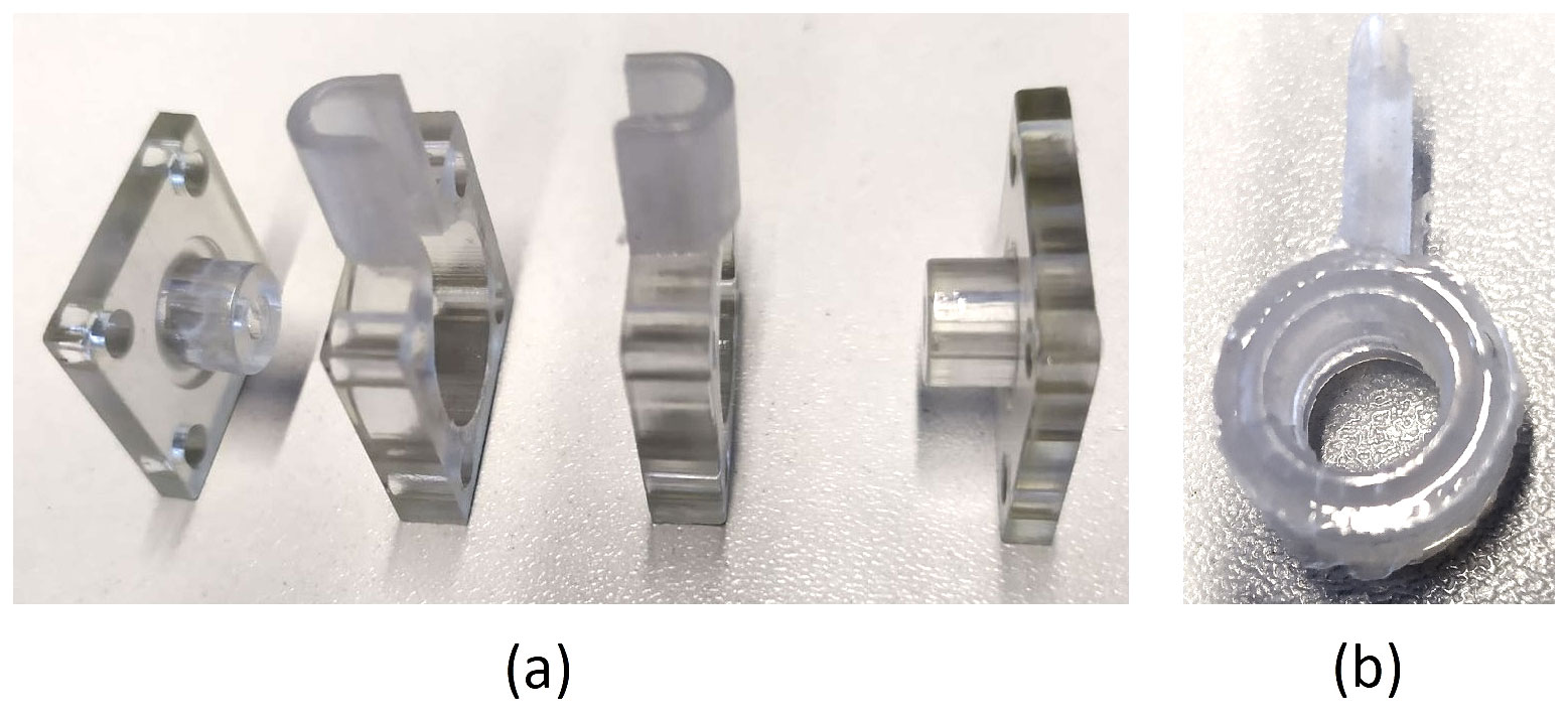
The main part of this setup is the sample chamber, as shown in Fig. 1. The purpose of this custom-built part in the form of a hollow cylinder is to carry the liquid solution. It is made from casting silicone (SF45, Silikonfabrik; see Fig. 1b), which is highly chemically resistant against alkaline solutions and additionally facilitates proper sealing due to its high elasticity. When installed, the chamber is compressed by two round crystal quartz disks. In this way, both disks are in direct contact with the sample on one side each. The sample chamber was designed for small sample volumes of approximately 0.5 mL.

Figure 1Cross section of the parts surrounding the sample: (a) quartz disks, (b) sample chamber, (c) injection needle (the second one is behind the first and, therefore, not visible in this view) and (d) sample fluid.
To inject the liquid, two syringes, one to inject the test fluid and one to simultaneously remove the air from the chamber, are used. The injection needles pierce small holes in the chamber wall when they are first inserted. Because of the high elasticity of the chamber the injection sites are self-sealing even when the injection needles are removed after sample injection.
Figure 2 shows different tested geometries of the sample chamber. For conductivity measurements, the chamber geometry in Fig. 2a is used due to its constant cross-sectional area. The geometry in Fig. 2b contains space for gas accumulation at the top. This turned out to be crucial for experiments at elevated temperatures, where gas bubbles develop more easily and have a negative impact on the measurement accuracy. The geometry in Fig. 2c shows an additional space to collect particles, which sediment at the bottom. Zeolites can reach sizes of several micrometers and, hence, are subject to sedimentation.
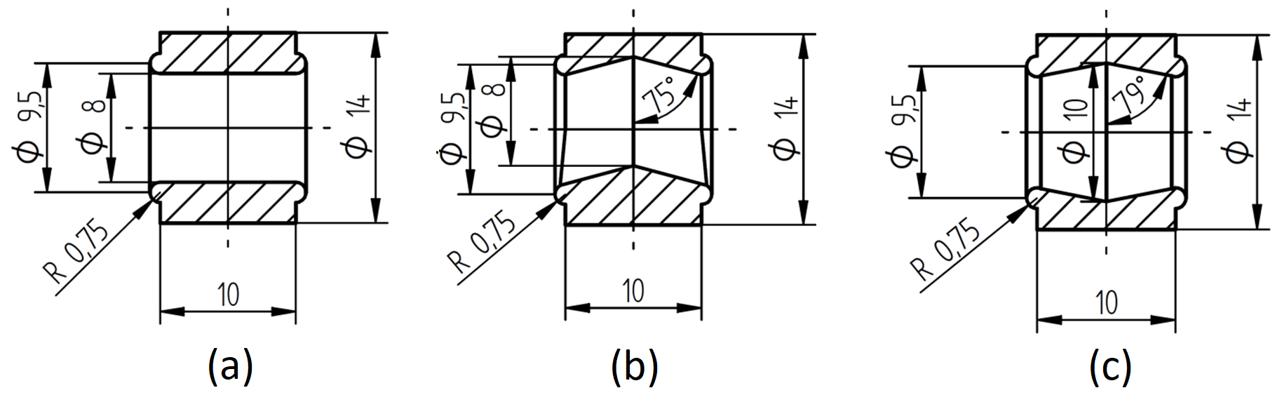
Figure 2Cross section of different reactor chambers: (a) simple cylindric chamber, (b) chamber with space for gas accumulation on the top, and (c) chamber with space for gas accumulation on the top and particle sedimentation on the bottom.
For all measurements, besides the conductivity measurements, the geometry according to Fig. 2c was used. To cast the sample chamber, a mold was printed, using a precision photopolymer 3D printer (Objet30 Pro, Stratasys) and photopolymer (VeroClear, Stratasys). To separate the mold from the silicone part after curing, the former was constructed from four screw-fastened parts, as shown in Fig. 3a.
2.2 Chamber housing
The chamber housing contains the sample chamber, the quartz sensors and the auxiliary components, such as O-rings. The quartz disks were squeezed against the sample chamber by means of a 3D printed housing. In Fig. 4, the parts of this housing, including the sample chamber, are shown. Figure 4a, b and h were also 3D printed using the aforementioned system (Stratasys Objet30 Pro) and a high-temperature-resistant photopolymer (Stratasys RD525).
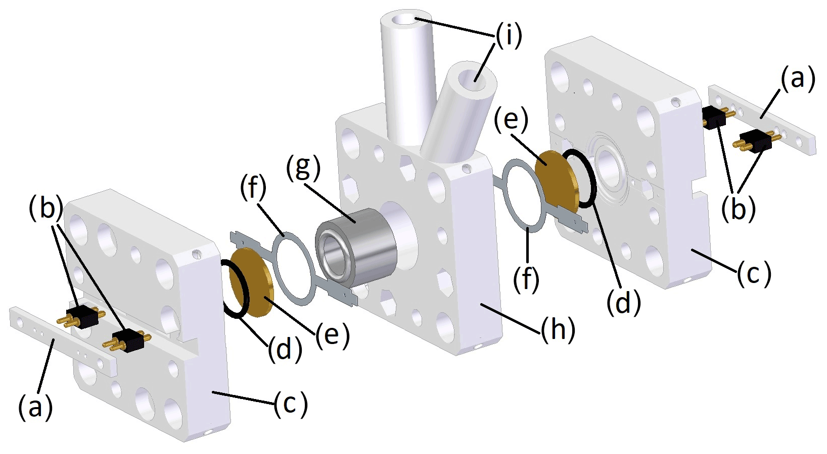
Figure 4Exploded view of the chamber housing consisting of (a) the counter bar, (b) spring pins for contacting the quartz electrodes, (c) the side parts, (d) the O-rings, (e) the quartz disks, (f) the contact ring, (g) the sample chamber, (h) the middle part and (i) the holes for syringes with injection needles.
To contact the two quartz crystals, custom-made contact rings etched out of a nickel silver sheet, as similarly employed by Reichel et al. (2010), in combination with spring pins (811-S1-002-10-017101, Preci-Dip), were used (see Fig. 4b and f). The O-rings (Fig. 4d) facilitate proper bearing on the dry side.
2.3 Temperature control
The chamber housing is placed in an aluminum box, whose temperature is controlled by two Peltier elements (Nesarajah and Frey, 2016), two Pt100 temperature sensors and custom-made electronics. To ensure a failure-free operation and fast equilibration times, the cool side of the Peltier elements are equipped with ventilated heat sinks (Fig. 5). The fully assembled setup is shown in Fig. 6. This approach to control the temperature has been successfully implemented and tested for other devices (Ecker et al., 2021). The major aim was to control the temperature at a constant value; in the considered temperature range between 0 and 80 ∘C, changes in temperature set points led to equilibration times in the order of a few minutes.

Figure 5Temperature regulation consisting of (a) an aluminum housing, (b) a heat sink, (c) a Peltier element, (d) a 3D printed heat sink mount and (e) a fan.
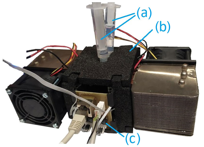
Figure 6Assembled setup consisting of (a) syringes for fluid injection, (b) thermal insulation and (c) a multiplexer.
2.4 Operation
The whole setup was operated with a Raspberry Pi 3B+ computer and a custom-made electronics board. In Fig. 7, this board is shown, including marked areas for its different sub-circuits. An analog–digital converter (AD7124-4 BRUZ, Analog Devices) was used for the readout of the Pt100 temperature sensor signal.
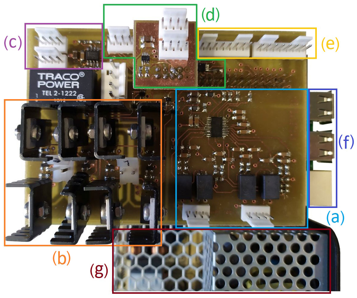
Figure 7Custom-made evaluation board consisting of (a) a temperature measurement circuit, (b) H-bridges, (c) a fan control, (d) a voltage and current output, (e) connectors for stepper motors, (f) Raspberry Pi ports, and (g) power supplies.
Controlling the current through the Peltier elements with pulse-wide modulated signals is facilitated by two H-bridges with high-current metal–oxide–semiconductor field-effect transistors (MOSFETs). The analog–digital converter in combination with an operational amplifier and a current measurement enables optional voltage or current-controlled output.
A dedicated readout unit (QCM50, Micro Resonant) in combination with a multiplexer (see Fig. 6c) and a Raspberry Pi embedded computer were used to capture the resonance frequencies and the quality factors of both quartz disks over time. The measurement data were collected using a custom-written Python code and were stored on the Raspberry Pi. In addition, a graphical user interface was programmed to adjust the set-point temperature of the setup.
3.1 Viscosity measurements
To measure viscosity (η), two identical AT-cut quartz disks that operate in thickness-shear mode were used. To determine the viscosity–density product from the measured values of resonance frequency (fr) and quality factor (Q), the frequency-dependent acoustic impedance (Zfl) for Newtonian fluids (Follens et al., 2009; Reichel et al., 2014; Vogelhuber-Brunnmaier and Jakoby, 2012) in the three-parameter form was used:
where Vfl represents the effective fluid volume, Afl is the effective shear-wave interaction surface, Lfl is the effective length of viscous damping, ρ is the density of the sample fluid, j is the imaginary unit and ω=2πfr is the angular frequency of the oscillation. With the assumption that the in-plane motion is dominant, the model is reduced to
The unloaded resonator is characterized by an angular resonance frequency ω0, a mass coefficient m0, and a low intrinsic damping expressed as the unloaded quality factor Q0. The resonance frequency and quality factor in the loaded case are then expressed using the real ℜ and the imaginary ℑ parts of Eqs. (1) or (2) as follows:
The viscosity–density product according to Eq. (2) can be derived either from the resonance frequency or the quality factor. Two reference measurements in known fluids or gases are necessary to determine the unknown constants Afl and m0. Air, deionized water and NaOH with known concentrations are used for this purpose. Furthermore, to calculate the viscosity, the density of the sample is required. The density values from the literature at known temperatures are used, and no variation during the process is assumed.
3.2 Electrical conductivity measurements
Electrical conductivity is determined via electrochemical impedance spectroscopy (EIS). A potentiostat (Reference 600+, Gamry Instruments) performs the electrical impedance measurements between the two electrodes of the quartz sensors, which are in contact with the sample. Note that the present approach represents a combination of a dual QCMD setup with a potentiostat impedance measurement. Thus, while the required sensors are integrated in the devised measurement chamber, the readout electronics are still separate. For a commercial integrated EQCMD device, of course, the integration of the electronics into a single unit is practicable.
A first-order model for the impedance of the liquid in terms of a resistor in series with a capacitance is employed. The former models the Ohmic (ionic) resistance of the liquid sample, and the latter captures the effect of the electrochemical double layer at the electrode–liquid interface. For higher frequencies, the capacitive contribution is negligible, resulting in a phase shift of zero. Consequently, this impedance represents the Ohmic resistance of the sample and a constant resistance R0, representing the resistance of wires and connections. R0 is first determined with a reference measurement using a conductivity standard with conductivity σS. If the length l and the cross section A of the sample chamber as well as the electrical conductivity σ of the sample are known, R0 can be calculated using Pouillet's law and the measured resistance R (value of impedance measurement with the minimal phase shift) according to
After this calibration, for further measurements, the electrical conductivity σ of the sample can be calculated from Eq. (5) yielding
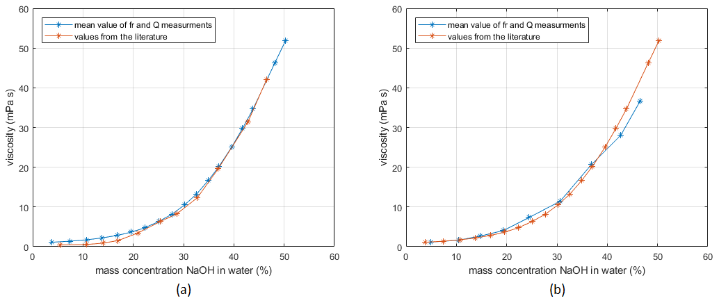
Figure 8Measured viscosity at 25 ∘C with (a) quartz with a planar surface (WTiAu0514, LapTech Precision Inc.) and (b) quartz with a convex surface (S-CAAAB-5MG03, Taitien Electronics Co., Ltd.) compared to values from the literature (Sipos et al., 2000).
3.3 Zeolite precursor liquid
Zeolite synthesis liquids (ZPLs) are prepared following a slightly altered methodology as explained by Van Tendeloo et al. (2015). Firstly, tetraethylorthosilicate (TEOS) was mixed with sodium hydroxide solution to achieve a molar ratio of 1 part TEOS (98 %, Acros Organics), 1 part 1 NaOH (>98 %, Sigma-Aldrich), and 25 parts H2O (Milli-Q), resulting in hydrolysis of TEOS. After 24 h of mechanical agitation, the mixture was rested, leading to phase separation into a top ethanolic water phase and a dense bottom phase, void of bulk water, containing small silicate oligomers and weakly hydrated sodium and hydroxide ions. After 3 d, this bottom phase, called hydrated silicate ionic liquid (HSIL), was collected and then mixed with sodium hydroxide, aluminum hydroxide (reagent grade, Sigma-Aldrich) and water to achieve a molar composition of 0.5 Si(OH)4 : 0.028 Al(OH)3 : 1 NaOH : 5 H2O. Homogenizing this mixture by mechanical agitation for 24 h finally yields the zeolite precursor liquid (ZPL), characterized by a single, transparent phase. Choosing a synthesis temperature of 60 ∘C, zeolite yield (white precipitate) is observable within several days, and synthesis can be considered complete after 1 week.
4.1 Viscosity
The setup is tested with viscosity measurements using NaOH solutions of various concentrations. The results are compared to data from the literature (Sipos et al., 2000). Testing the quartz disks with the planar surface on the measurement side (supplier and manufacture by LapTech Precision Inc.), the calibration with gases is problematic, as damping of the sample chamber and the O-rings causes large errors. Therefore, instead of calibration with air and water, the setup is calibrated with water and NaOH (mass concentrations 46 %) using the literature values from Sipos et al. (2000). The measurement results are shown in Fig. 8a.
The quartz disks from Taitien Electronics Co., Ltd. (supplier Digi-Key Electronics), which have a convex surface, were calibrated by measurements in air and water. As visible in Fig. 8, both measurements show that the measured values are in reasonable agreement with reference values. To get more accurate measurement data over this wide range of viscosities, calibration with viscosity standards on several different points would be necessary.
4.2 Electrical conductivity
For the electric conductivity measurement, the setup is first calibrated with a conductivity standard (Consort B562 calibration solution 1 M KCl, σS=11.18 S m−1 at 25 ∘C). Using this known conductivity of the sample, the mechanical dimensions of the sample chamber, the measured value of R and Eq. (6), the constant is calculated as R0=7.050 Ω. In Fig. 9, the Bode diagram of this measurement is shown. It can be seen that our model fits adequately. For all conductivity measurements, it is very important that the chamber is absolutely free of air bubbles. Air bubbles locally decrease the cross section of the sample and, therefore, cause an increase in the measured solution resistance (i.e., a drop in conductivity). Furthermore, as temperature has a drastic effect on ionic conductivity, the sample was loaded 1 h prior to the measurement to ensure a uniform and steady temperature distribution.
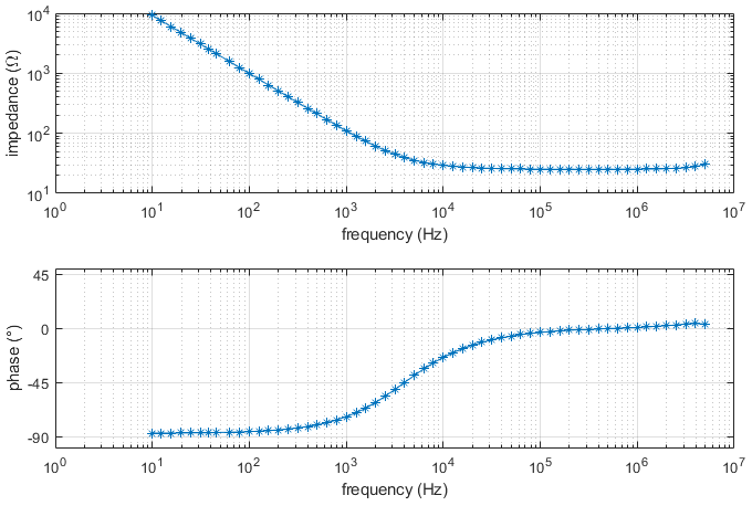
Figure 9Bode diagram of electrical conductivity measurement using Consort B562 calibration solution 1 M KCl.
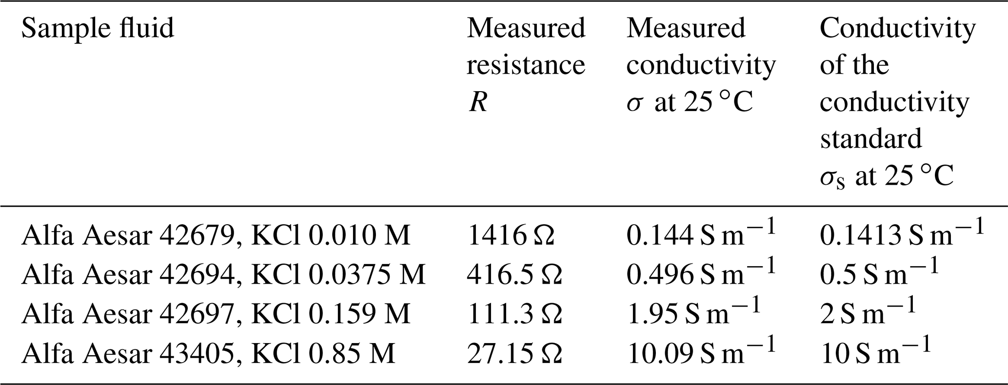
To validate our setup, measurements with other standards (see Table 1) were performed. The calculated values for electric conductivity are presented in Table 1. As can be seen, the measurement values are in good agreement with the nominal conductivity values.
Table 1Comparison of the measured conductivities and those given by the conductivity standards.
4.3 Zeolite precursor liquid
For monitoring the crystallization process, we put ZPL at 60 ∘C into the sample chamber. After the first measurements, we noticed that the gold electrodes of both quartz disks, which were in contact with the highly alkaline sample, partly degraded over the experimental period of about 7 d. An attempted solution to this issue was to cover the electrodes with thin layers of polymethyl methacrylate (PMMA) via spin coating. PMMA is highly resistant to alkaline solutions and easily deposited in micrometer-thick layers. With more massive layers, the measurement sensitivity of the QCMD would decrease due to the damping in the polymer layer. Additionally, as PMMA is a dielectric material, the electrical conductivity measurements become more difficult.
Figure 10 shows a measurement with and without the PMMA layer. As expected, the two measurement curves differ in sensitivity, which is apparent from the much lower quality factor of the coated quartz than the uncoated one. However, both measurements show a similar course. From the decreasing resonance frequency and quality factor over time, we assume the deposition of emerging particles on the quartz surfaces.
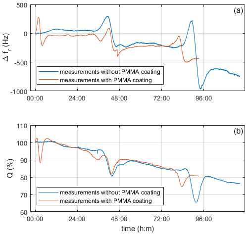
Figure 10Comparison of coated and uncoated quartz electrodes during the measurement with ZPL and a reactor temperature of 60 ∘C. Panel (a) shows changes in resonance frequency vs. time, and panel (b) shows the quality factor in relation to the starting values vs. time.
One intriguing effect observed is that bumps periodically appear in all curves (Fig. 10). To identify, whether this comes from the crystallization process itself or from spurious artifacts, we tested solutions of sodium and potassium hydroxide at various concentrations as well as water. The liquids, which had a similar alkalinity to the precursor solution, showed these periodic bumps too; however, we did not observe them in water. The initial suspicion that resonance effects are associated with spurious standing pressure waves, as discussed by Beigelbeck and Jakoby (2004), was ruled out, as the bumps should then appear in water as well. Therefore, we assume that the bumps were due to degradation effects caused by the high alkalinity. Images of the electrodes before and after confirm the appearance of severe corrosion (Fig. 11).

Figure 11The surface of a quartz disk: (a, b) front and back side of a new disk, (c, d) front and back side without a PMMA layer, and (e, f) front and back side with a PMMA layer after measurement with ZPL.
In the on-going investigation, coating materials with higher protective properties are tested to avoid electrode degradation.
In this paper, a setup for the characterization of liquids with the perspective of monitoring crystallization processes is presented. The novelty of this setup is the realization of viscosity and conductivity measurements using two quartz crystal microbalances with dissipation readout. Additionally, there is the possibility to apply an electric field through the sample, enabling the manipulation of charged particles, as they emerge, for instance, during zeolite synthesis.
Viscosity measurements with concentrated sodium hydroxide solutions at room temperature showed that the measured values are in reasonable agreement with values from the literature across a wide concentration range. For conductivity measurements, the setup was first calibrated with a standard liquid. Measurements with other conductivity standards showed that values were in good agreement with the nominal values for all performed measurements.
Monitoring the crystallization of zeolites based on these parameters remains a subject for further investigation. The main issue is the electrochemical degradation of the quartz electrodes by the highly alkaline samples. Despite coating the quartz surfaces with a protective PMMA layer, corrosion still occurred, overshadowing the change in viscosity caused by the crystallization reaction.
The formation of gas bubbles in the heated sample is observed occasionally, which negatively affects the measurement. Nevertheless, the goal of realizing a combined dual QCMD and electrochemical impedance measurement cell was achieved.
The data presented in this publication are not publicly available. They can be made available from the authors upon reasonable request.
RE, ND and EKR developed the setup design. RE fabricated the setup based on the first version from EKR. All co-authors contributed knowledge and ideas that helped to improve and develop the setup, resulting in the final version. RE developed the software, the electronics and carried out the measurements. RE, ND, BJ and EKR evaluated the measured data. RE prepared the paper with support from all co-authors.
At least one of the (co-)authors is a member of the editorial board of Journal of Sensors and Sensor Systems. The peer-review process was guided by an independent editor, and the authors also have no other competing interests to declare.
Publisher's note: Copernicus Publications remains neutral with regard to jurisdictional claims in published maps and institutional affiliations.
This article is part of the special issue “Sensors and Measurement Science International SMSI 2021”. It is a result of the Sensor and Measurement Science International, 3–6 May 2021.
The authors would like to thank the technicians of the Institute for Microelectronics and Microsensors for their help in the procurement and production of materials.
This research has been supported by the Austrian Science Fund (grant no. I 3680) and the “LCM – K2 Center for Symbiotic Mechatronics” within the framework of the Austrian COMET-K2 program.
This paper was edited by Peter A. Lieberzeit and reviewed by two anonymous referees.
Beigelbeck, R. and Jakoby, B.: A two-dimensional analysis of spurious compressional wave excitation by thickness-shear-mode resonators, J. Appl. Phys., 95, 4989, https://doi.org/10.1063/1.1697637, 2004.
Dudášová, D., Silset, A., and Sjöblom, J.: Quartz Crystal Microbalance Monitoring of Asphaltene Adsorption/Deposition, J. Dispers. Sci. Technol., 29, 139–146, https://doi.org/10.1080/01932690701688904, 2008.
Ecker, R., Doppelhammer, N., Jakoby, B., and Reichel, E. K.: Dual Electrochemical Quartz Crystal Microbalance with Dissipation Monitoring, in: Proceedings of SMSI 2021 Conference, 3–6 May 2021, Nurnberg, Germany, 101–102, https://doi.org/10.5162/SMSI2021/A9.3, 2021.
Follens, L. R., Reichel, E. K., Riesch, C., Vermant, J., Martens, J. A., Kirschhock, C. E., and Jakoby, B.: Viscosity sensing in heated alkaline zeolite synthesis media, Phys. Chem. Chem. Phys., 11, 2854–2857, https://doi.org/10.1039/B816040F, 2009.
Johannsmann, D.: The Quartz Crystal Microbalance in Soft Matter Research, in: Edition 1, Soft and Biological Matter, Springer, Cham, https://doi.org/10.1007/978-3-319-07836-6, 2015.
Li, Y., Liu, M., Xiang, C., Xie, Q., and Yao, S.: Electrochemical quartz crystal microbalance study on growth and property of the polymer deposit at gold electrodes during oxidation of dopamine in aqueous solutions, Thin Solid Films, 497, 270–278, https://doi.org/10.1016/j.tsf.2005.10.048, 2006.
Liu, X., Mäki-Arvela, P., Aho, A., Vajglova, Z., Gun'ko, V. M., Heinmaa, I., Kumar, N., Eränen, K., Salmi, T., and Murzin, D. Y.: Zeta Potential of Beta Zeolites: Influence of Structure, Acidity, pH, Temperature and Concentration, Molecules, 23, 946, https://doi.org/10.3390/molecules23040946, 2018.
Nesarajah, M., and Frey, G.: Thermoelectric Power Generation: Peltier Element versus Thermoelectric Generator, in: Proceedings of the IECON 2016 – 42nd Annual Conference of the IEEE Industrial Elections Society, 23–26 October 2016, Florence, Italy, 4252–4257, https://doi.org/10.1109/IECON.2016.7793029, 2016.
Reichel, E. K., Riesch, C., Keplinger, F., Kirschhock, C. E., and Jakoby, B.: Analysis and experimental verification of a metallic suspended plate resonator for viscosity sensing, Sens. Actuat. A, 162, 418–424, https://doi.org/10.1016/j.sna.2010.02.017, 2010.
Reichel, E. K., Heinisch, M., Jakoby, B., and Vogelhuber-Brunnmaier, T.: Efficient numerical modeling of oscillatory fluid-structure interaction, in: Proceedings of IEEE SENSORS 2014, 2–5 November 2014, Valencia, Spain, 958–961, https://doi.org/10.1109/ICSENS.2014.6985161, 2014.
Rodahl, M., Höök, F., Krozer, A., Brzezinski, P., and Kasemo, B.: Quartz crystal microbalance setup for frequency and Q-factor measurements in gaseous and liquid environments, Rev. Sci. Instrum., 66, 3924–3930, https://doi.org/10.1063/1.1145396, 1995.
Shpigel, N., Levi, M. D., and Aurbach, D.: EQCM-D technique for complex mechanical characterization of energy storage electrodes: Background and practical guide, Energy Stor. Mater., 21, 399–413, https://doi.org/10.1016/j.ensm.2019.05.026, 2019.
Singh, K. and Blanford, C. F.: Electrochemical Quartz Crystal Microbalance with Dissipation Monitoring: A Technique to Optimize Enzyme Use in Bioelectrocatalysis, Chem. Cat. Chem., 6, 921–929, https://doi.org/10.1002/cctc.201300900, 2014.
Sipos, P. M., Hefter, G., and May, P. M.: Viscosities and Densities of Highly Concentrated Aqueous MOH Solutions (M+) Na+, K+, Li+, Cs+, (CH3)4N+) at 25.0∘, C. J. Chem. Eng. Data, 45, 613–617, https://doi.org/10.1021/je000019h, 2000.
Van Tendeloo, L., Haouas, M., Martens, J. A., Kirschhock, C. E., Breynaert, E., and Taulelle, F.: Zeolite synthesis in hydrated silicate ionic liquids, Faraday Discuss., 179, 437–449, https://doi.org/10.1039/C4FD00234B, 2015.
Vogelhuber-Brunnmaier, T., and Jakoby, B.: Efficient spectral domain formulation of loading effects in acoustic sensors, Sens. Actuat. A, 186, 38–47, https://doi.org/10.1016/j.sna.2011.12.052, 2012.
Yang, Z., Dixon, M. C., Arck, R. E., and Trahey, L.: Quantification of the Mass and Viscoelasticity of Interfacial Films on Tin Anodes Using EQCM-D, ACS Appl. Mater. Interf., 7, 26585–26594, https://doi.org/10.1021/acsami.5b07966, 2015.
Yi, P. and Chen, K. L.: Release Kinetics of Multiwalled Carbon Nanotubes Deposited on Silica Surfaces: Quartz Crystal Microbalance with Dissipation (QCM-D) Measurements and Modeling, Environ. Sci. Technol., 48, 4406–4413, https://doi.org/10.1021/es405471u, 2014.