the Creative Commons Attribution 4.0 License.
the Creative Commons Attribution 4.0 License.
 | 20 Apr 2023
Chemical hydrogel sensors based on the bimorph effect with short response time
Stefan Schreiber
Nadja Steinke
Gerald Gerlach
Hydrogel sensors are well suited to measuring the concentration of substances in liquids, and, because the hydrogel is biocompatible, they are ideal for medical use. Hydrogels change their volume in response to stimuli. The larger the hydrogel, the more pronounced the measurement signal. However, a larger volume also leads to slower swelling due to the longer diffusion paths. One method of determining the degree of swelling is to measure the swelling pressure using a piezoresistive pressure sensor. With current approaches, measurement times of several minutes can be achieved. By exploiting the bimorph effect, we were able to reduce the thickness of the hydrogel and, thus, reduce the response time of the entire sensor to less than 1 min. The aim of this paper is now to show how a sensor with short response times can be designed and manufactured and, in particular, how to find a suitable hydrogel composition, how to appropriately structure the hydrogel layer and how a robust adhesion of the hydrogel to the sensor chip can be achieved. As a result, we were able to show that such hydrogel sensors with response times of just a few seconds are possible.
- Article
(742 KB) - Full-text XML
- BibTeX
- EndNote


As Katchalsky (1949) shows, elastic polymer networks (hydrogels) first aroused interest for use as actuators in 1949. Due to their hydrophilic nature, hydrogels swell when in contact with water. With the help of functional groups, hydrogels also respond to stimuli such as changes in ion concentration, pH value and temperature, to name just a few. By varying the polymer composition, Erfkamp et al. (2019a, b, c) have shown how the concentrations of other solutes such as urea, ethanol or ammonia can be determined. The swelling behaviour can be measured by optical (e.g. refractometric, photometric), mechanical (e.g. piezoresistive, microgravimetric) and electromechanical (e.g. capacitive, conductive) methods (Gerlach et al., 2021).
The piezoresistive method uses a pressure sensor to measure the mechanical force (swelling pressure) generated by the hydrogel as it swells. The response time of the sensor depends mainly on the response time of the hydrogel, which is influenced by parameters such as thickness, porosity and composition. Schulz et al. (2012) showed that a reduction in the response time of the sensor can also be achieved by using the force compensation method. In this method, an external counterforce is used to counteract the deflection of the hydrogel. In this way, swelling can be virtually prevented and the dynamics decisively improved. The force required to compensate is then the new measured value. Binder (2019) used this method by combining two hydrogels to form an interpenetrating network (IPN). While one hydrogel reacts to the analyte by swelling, the other hydrogel is used to counteract this swelling and thus keep the volume of the IPN constant. The counteracting force is controlled by temperature, which represents the new measurement signal. In this way, the response time was reduced from 11.3 min (without force compensation) to only 3.5 min.
As mentioned above, the response time of a hydrogel depends on its thickness. In the previous work, a cylindrical hydrogel was clamped at the ends between a solid wall and a piezoresistive sensor. The most important parameter for the response time is therefore the diameter of the cylinder. Reducing the diameter would result in a lower force and a more unstable structure, leading to inaccurate measurements.
The humidity switches for gas sensors by Gulnitzkij and Gerlach (2020b) showed how a hydrogel can be used to exploit the bimorph effect. This effect occurs when two bonded materials with different expansion properties are excited to change their volumes. If one material expands more than the other, the bond is deflected. In this sensor, the hydrogel is bonded to the thin silicon membrane of the pressure sensor. Chemical excitation causes the hydrogel to swell, resulting in deflection of the flexure plate and a corresponding measurable signal. With thermal excitation, the temperature-induced deformation of the flexure plate is many times smaller than that caused by the hydrogel and can therefore be considered quasi-static.
This paper presents a novel structure that combines force compensation with the bimorph effect. This leads to new challenges that need to be addressed. One of them is to adjust the physical parameters of the hydrogel as one of the two components of the bimorph. The normally soft and highly swelling hydrogel needs to be made stiffer in order to bend the silicon wafer. Secondly, a strong bond must be created between the hydrogel and the silicon plate to withstand both the bending and the flow of the analyte.
Figure 1 shows the structure of the sensor used schematically. A piezoresistive pressure sensor (C41, TDK Electronics) with a measuring range of up to 25 mbar is used to measure the swelling. It is mounted in such a way that the cavity with the socket forms a fluidic chamber that can be filled via the inlet and outlet. The hydrogel is structured on the inside of the thin bending plate and thus exposed to the analyte. Peltier elements are mounted underneath the socket to control the temperature of the sensor chip and, thus, the hydrogel. A temperature-sensitive diode is coupled to the C41 to measure the current temperature.
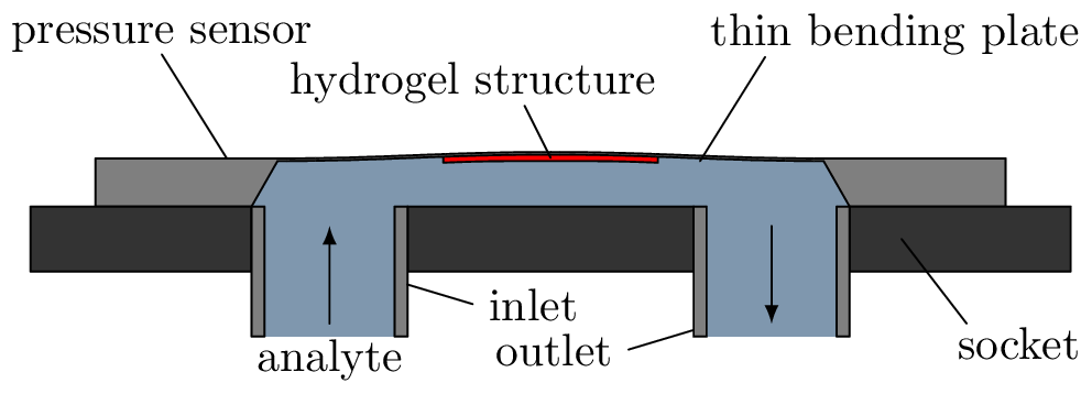
Figure 1Cross-section of the sensor used. The cavity between the socket and the sensor chip forms a fluid chamber. Swelling of the hydrogel on the inside of the bending plate results in deflection due to the bimorph effect and thus a sensor signal dependent on the degree of swelling.
2.1 Hydrogel composition
To exploit the bimorph effect, the hydrogel has to have the right mechanical properties with respect to Young's modulus, which is set by the amount of crosslinker. If the hydrogel is too stiff (high crosslinker content), then it will not be able to swell. If the hydrogel is too soft, it will swell just in the out-of-plane direction which again avoids the bimorph bending. To find the right composition, several hydrogels with different concentrations were prepared and analysed in free swelling. The most promising composition is shown in Table 1.
Table 1Composition of components that are used for polymerisation. The first three form the hydrogel and constitute 100 %.
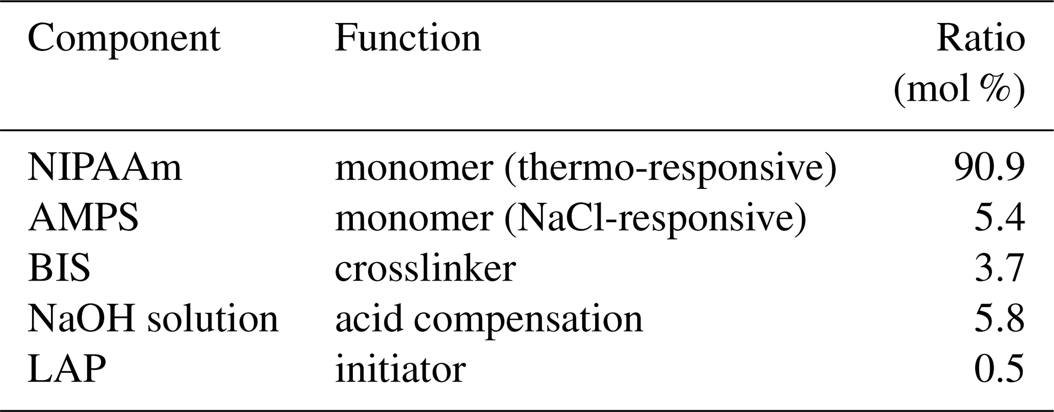
The monomers 2-acrylamido-2-methylpropane sulfonic acid (AMPS) and N-isopropylacrylamide (NIPAAm) together with the crosslinker N, N′-methylene-bisacrylamide (BIS) form the hydrogel. Polymerised AMPS reacts to the increase in ion concentration by deswelling due to the sulfonic acid groups. In contrast, polymerised NIPAAm reacts to increasing temperature by swelling. Lithium phenyl-2,4,6-trimethylbenzoylphosphinate (LAP) is used as a photosensitive initiator to start the polymerisation process upon irradiation with UV light at a wavelength of 360 nm. The NaOH solution compensates for the acidic pH of AMPS and is rinsed out after polymerisation along with the remaining initiator.
2.2 Sensor preparation
The bimorph effect requires a strong bond between the silicon membrane and the hydrogel. This was achieved using an adhesion promoter in the form of a self-assembling monomer layer. 3-Aminopropyltriethoxysilane (APTES) has a silane group at one end that forms a bond with the silicon of the sensor chip. The other end with the aminopropyl group then straightens out and is available for polymerisation with the hydrogel. The chip surface is exposed to APTES dissolved in isopropanol for at least 3 h. The excess is then washed off.
The structure of the hydrogel influences both the direction and the strength of the deflection. The desired hydrogel structure is a circular disc with a diameter of 1.65 mm and a height of 20 µm. Gulnitzkij and Gerlach (2020a) have shown that a ratio between the diameter of the hydrogel and the edge length of the bending plate of 0.5 is optimal for the largest possible deflection. The height of 20 µm was chosen because this is the thickness of the bending plate.
A microcontact printer μCP 4.1 (GeSiM mbH, Großerkmannsdorf) is used to structure the hydrogel. In a first step, a poly(dimethylsiloxane) (PDMS) stamp with the shape of the hydrogel structure is formed from a template. The cavity of the stamp is filled with the pre-gel solution and then pressed onto the sensor membrane with the μCP at a pressure of 20 kPa for 1 min. The structure is polymerised for 1 min under UV light (wavelength range 320–500 nm, OmniCure S1500, Excelitas Technologies GmbH, Wiesbaden).
2.3 Measurement setup
The measurement setup shown in Fig. 2 is used to characterise the hydrogel sensor. Since the pressure sensor detects even very small pressure fluctuations, the analyte flow must be pulsation-free. To achieve this, the measurement setup is operated with syringe pumps (CETONI GmbH, Korbussen), which can generate flow rates in the range of 1 to 5000 µL min−1. One syringe is filled with salt solution (1 mol L−1 NaCl in H2O) and another one with distilled deionised water (DDI H2O). A defined concentration can be set by adjusting the respective flow rates. The sum of the two flow rates is always 100 µL min−1. Both liquids are passed through a DEGASi® Classic degasser (dichrom GmbH, Haltern am See) to remove any gas inclusions that may be present when the syringes are drawn up. The syringe pumps then deliver the sample solution through a micromixing module into the sensor. To avoid unwanted back pressure, the sensor outlet is connected to an open-pressure equalisation vessel. This is emptied with the third syringe, and the waste water is collected in a tank.
To apply the temperature, the sensor is mounted on two Peltier elements. These are controlled by a controller (BelektroniG GmbH, Freital). In addition to the temperature sensor on the sensor chip, the controller measures two other temperature sensors located directly above the circuit board and outside the housing.
Both the syringe pumps and the Peltier elements are controlled by separate software, which can also be used to program and run specific test scenarios independently. The software records data such as flow rate, temperature and pressure. The latter is measured as a voltage across a Wheatstone bridge. As the measurement data are recorded by two different programs, the time stamp is used to synchronise the measurement data. In addition, the delay between the start of the pump and the arrival of the analyte at the sensor is calculated so that the chemical stimulation matches the data from the sensor.
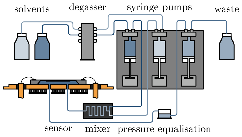
Figure 2The fluidic setup. To mix an analyte at a specific concentration, the volume flow ratio of two syringes is controlled. The degasser is used to prevent pressure fluctuations caused by air bubbles in the liquid. The sensor itself is mounted on a Peltier element to control temperature.
2.4 Sensor behaviour
The hydrogel is bi-sensitive; i.e. it can swell or deswell with both a change in salt concentration cion (by AMPS) and a change in temperature ϑ (by NIPAAm). As the components of the hydrogel and their composition can be changed, both sensitivity and measurement range can be adjusted to suit the measurement task.
Figure 3 shows a block diagram of the sensor system. It can be used in two different modes. In the deflection mode, without feedback loop (grey path), the stimuli cause a deswelling/swelling of the hydrogel, which can be detected as a voltage U𝖼𝗁𝗂𝗉 by the piezoresistive sensor chip. In compensation mode, with feedback loop, a deflection is set by U𝗌𝖾𝗍, and the temperature ϑ𝗉𝖾𝗅 is controlled to maintain this deflection. If the AMPS part changes its volume due to a change in concentration, the temperature is adjusted so that the NIPAAm part compensates for this swelling. This makes the temperature ϑ𝗉𝖾𝗅 the new measurement result.
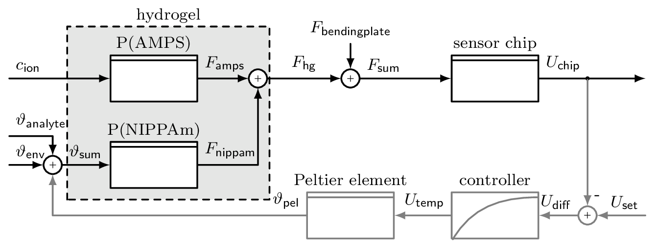
Figure 3Block diagram of the hydrogel sensor. The hydrogel consists of two polymers, each influenced by a different stimulus, P(AMPS) by ion concentration cion and P(NIPAAm) by temperature ϑsum. The force Fhg caused by the swelling of the hydrogel is converted into a voltage Uchip by the sensor chip. To use the force compensation, the grey path is added, where a certain deflection can be set with Uset. Then the controller changes the temperature of the Peltier element ϑpel to adjust the degree of swelling.
There are some disturbances affecting the system generally. Primarily, the temperature of the environment ϑenv and the analyte ϑanalyte influences the swelling behaviour of the NIPAAm part. To reduce this, the system is encapsulated in a housing, and the analyte is passed through a tube inside the housing so that it is preheated. However, the proximity of the Peltier element causes a small temperature perturbation. The other influence is caused by the bending plate to which the hydrogel is attached. When the hydrogel causes a deflection, then the bending plate creates a force Fbendingplate that is directed against the deflection. Therefore, the hydrogel needs more time to overcome this force during deswelling and is assisted by the force during swelling. This results in different response times for the two different stimulus directions.
The responses to both stimuli (ion concentration, temperature) are first measured separately without force compensation to characterise the sensor. This results in two test scenarios: one stimulus is applied alternately, while the other is held constant.
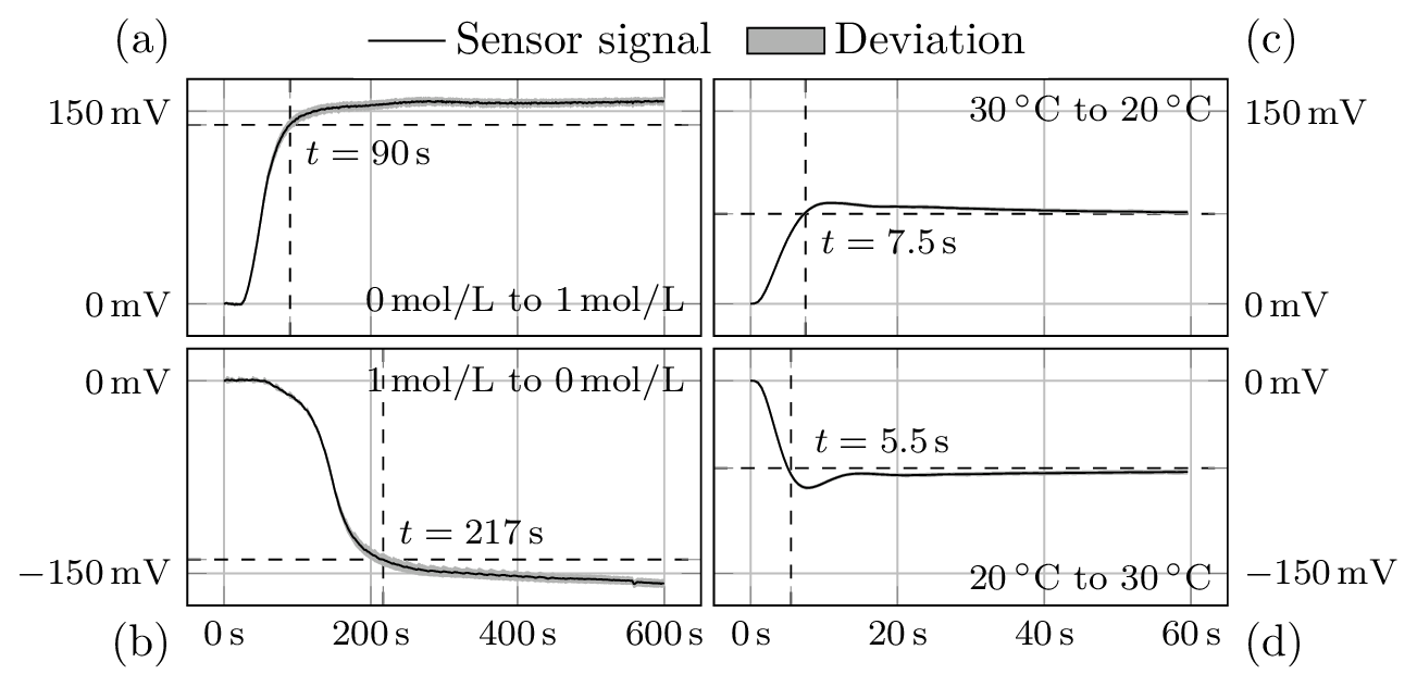
Figure 4Response of the sensor to changes in concentration (a, b) and temperature (c, d). While the measurement signal increases with increasing concentration (a), it decreases with increasing temperature (d).
To characterise the salt sensitivity, the ion concentration of the analyte is varied between 0 and 1 mol L−1 every 10 min. Meanwhile, the temperature of the sensor is kept constant at 20 ∘C. For temperature sensitivity, the temperature is varied between 20 and 30 ∘C every minute while keeping the ion concentration constant at 0 mol L−1. The flow rate of the analyte is kept constant at 100 µL min−1 during both experiments. As the analyte flow causes heat dissipation which must be taken into account, the flow rate is essential during the temperature measurement.
Before and after each experiment, the sensor system is rinsed with deionised H2O to remove residues from the last measurement and possible air inclusions from the sensor change.
Figure 4 shows the sensor responses to the two test scenarios, i.e. either concentration or temperature change. The left column shows the average of the step responses to 24 concentration changes. The step response of the temperature stimulus is calculated from 220 repetitions and is shown in the right column. The standard deviations are shown as the grey area around the signal curve.
For a change in ion concentration from 0 to 1 mol L−1 and vice versa, the sensor requires 90 and 217 s respectively. The slowness of the hydrogel during swelling could be due to the hydrogel being more rigid in the deswollen state and thus having a higher modulus of elasticity. This means that it takes longer to re-expand. In addition, the proportion of AMPS, i.e. the proportion that responds to ion concentration, is only 5.4 %, which means that it has to compete with a large NIPAAm complex.
The hydrogel responds similarly quickly to temperature change in both directions of excitation, 5.5 and 7.5 s, and much faster than to concentration change. The faster swelling and deswelling times are advantageous because the NIPAAm part of the hydrogel is to be used as an actuator in compensation mode. In control engineering, it is important that the actuator is faster than the controlled system so that disturbances can be responded to before they affect the controlled system. As a rule of thumb, the actuator should be about 10 times faster than the controlled system, which is guaranteed here with a ratio of 1 : 12.
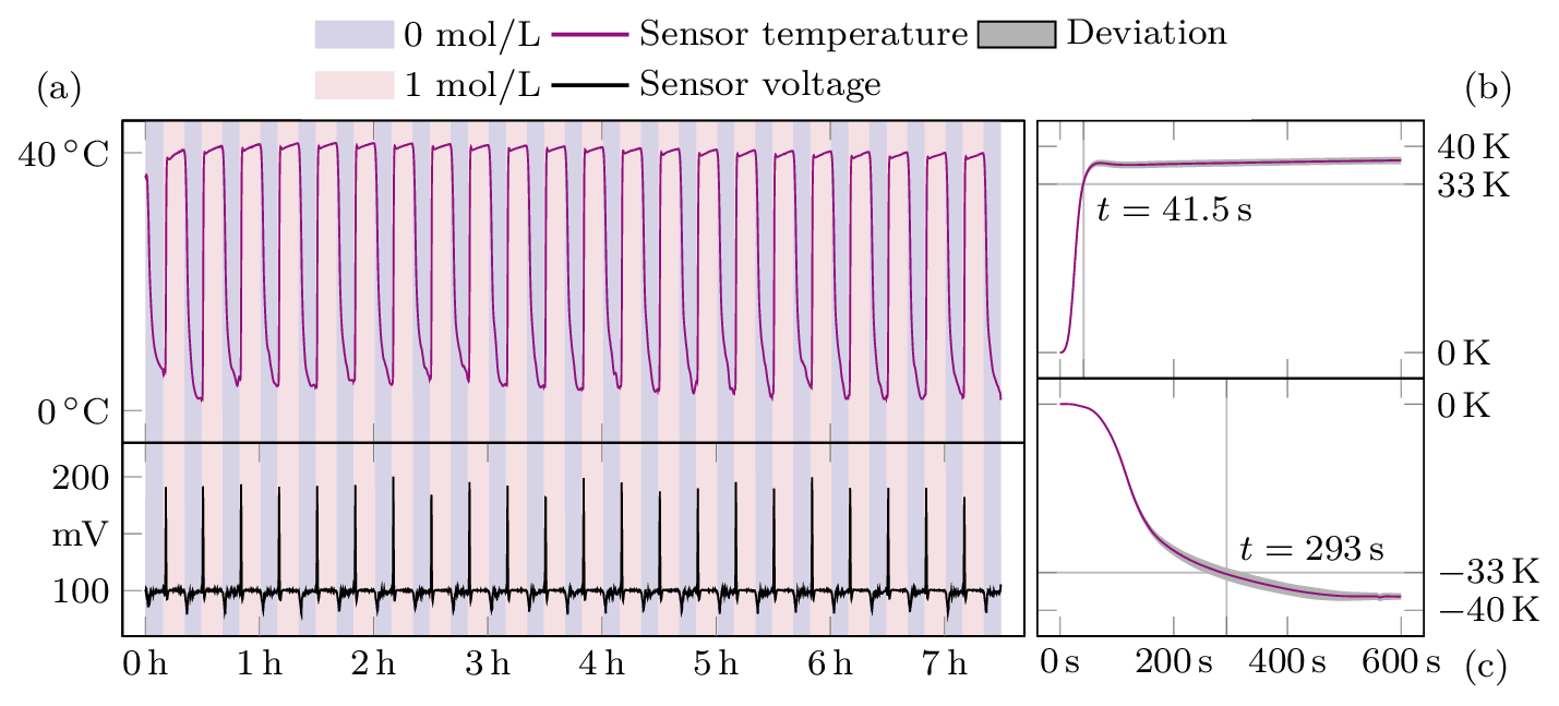
Figure 5Measurement results of the sensor in compensation mode. Panel (a) shows both the temperature and voltage of the sensor throughout the experiment. In the background the concentration changes are shown in colour. On the right, panels (b) and (c) summarise the mean values of the individual jumps.
Once the responses to each stimulus could be demonstrated, the system was put into force compensation mode. This was achieved by setting a target voltage Uset of 100 mV to maintain a certain level of swelling. The response of the sensor to the change in concentration is shown in Fig. 5. The temperature is regulated by the controller to maintain the value of 100 mV. Therefore the temperature now varies between 40 ∘C and about 5 ∘C. The measurement time for the rise of the stimulus has decreased from 90 to 41.5 s. In contrast, the time for the fall has increased to 293 s. This could be because, in addition to the effects already described, the temperature is around freezing and therefore strongly affects analyte flow. It can also be seen that the sensor voltage increases to almost 200 mV before the controller intervenes, suggesting that the control parameters are not optimally tuned to this controlled system and need to be optimised.
The reduction in measurement time can be further improved by the following steps. By adjusting the hydrogel composition, i.e. increasing the amount of AMPS, the response to the change in ion concentration becomes stronger and thus faster. As the sensor voltage in controlled mode is very different from the set 100 mV, it can be assumed that the hydrogel will swell too much before the controller counteracts this. This can be improved by increasing the P and adjusting the I parameters of the PI controller. The measuring range is also very ambitious with 0 to 1 mol L−1 (Binder, 2019, alternated between 0.01 and 0.10 mol L−1). It is therefore necessary to find the operating point of the sensor. This can be determined by recording the degree of swelling and the response to changes in concentration at different temperatures.
The aim of this work was to produce a hydrogel sensor with a significantly reduced response time compared to the current state of the art. By utilising the bimorph effect, the volume of the hydrogel could be reduced to a thin disc, which is only clamped on one side and thus better exposed to the analyte. The self-assembling monomer layer forms a very strong bond between the silicon plate and the hydrogel. Even without force compensation, the response to changes in ion concentration, at around 90 s, was faster than previous sensors. By using the compensation mode, the measurement time was further reduced to 41.5 s, an 80 % reduction compared to the previous 210 s.
Although there is still room for optimisation, such as adjusting the control parameters and the hydrogel composition, the results presented here show that this sensor concept is suitable for the development of hydrogel sensors based on the bimorph effect with very short response times.
According to the guidelines of the Deutsche Forschungsgemeinschaft (DFG), the presented data and codes in this publication are stored in an internal system. All measurement data and codes are not publicly available and can be accessed from the authors upon request.
Conceptualisation: SS and GG. Methodology: SS, NS, and GG. Experiment: SS and NS. Writing (original draft preparation): SS and NS. Writing (review and editing): SS and GG. Funding acquisition: GG.
The contact author has declared that none of the authors has any competing interests.
Publisher's note: Copernicus Publications remains neutral with regard to jurisdictional claims in published maps and institutional affiliations.
This research has been supported by the Deutsche Forschungsgemeinschaft (grant no. GRK 1865 – “Hydrogel-based Microsystems”).
This open-access publication was financed by the Saxon State and University Library Dresden (SLUB Dresden).
This paper was edited by Marco Jose da Silva and reviewed by two anonymous referees.
Binder, S. and Gerlach, G.: Intramolecular Force-compensated Hydrogel-based Sensors with Reduced Response Times, Technisches Messen, 86, 227–236, https://doi.org/10.1515/teme-2019-0004, 2019. a, b
Erfkamp, J., Guenther, M., and Gerlach, G.: Piezoresistive Hydrogel-Based Sensors for the Detection of Ammonia, Sensors, 19, 971, https://doi.org/10.3390/s19040971, 2019a. a
Erfkamp, J., Guenther, M., and Gerlach, G.: Hydrogel-Based Sensors for Ethanol Detection in Alcoholic Beverages, Sensors, 19, 1199, https://doi.org/10.3390/s19051199, 2019b. a
Erfkamp, J., Guenther, M., and Gerlach, G.: Enzyme-Functionalized Piezoresistive Hydrogel Biosensors for the Detection of Urea, Sensors, 19, 2858, https://doi.org/10.3390/s19132858, 2019c. a
Gerlach, G., Guenther, M., and Hartling, T.: Hydrogel-Based Chemical and Biochemical Sensors – A Review and Tutorial Paper, IEEE Sensors J., 21, 12798–12807, https://doi.org/10.1109/JSEN.2020.3042988, 2021. a
Gulnizkij, N. and Gerlach, G.: Modelling and model verification of an autonomous threshold sensor for humidity measurements, J. Sens. Sens. Syst., 9, 1–6, https://doi.org/10.5194/jsss-9-1-2020, 2020a. a
Gulnizkij, N. and Gerlach, G.: Bistable Threshold Humidity Sensor Switch with Rectangular Bimorph Bending Plate, Micromachines, 11, 569, https://doi.org/10.3390/mi11060569, 2020b. a
Katchalsky, A.: Rapid Swelling and Deswelling of Reversible Gels of Polymeric Acids by Ionization, Experientia, 5, 319-320, https://doi.org/10.1007/BF02172636, 1949. a
Schulz, V., Gerlach, G., and Röbenack, K.: Compensation method in sensor technology: a system-based description, J. Sens. Sens. Syst., 1, 5–27, https://doi.org/10.5194/jsss-1-5-2012, 2012. a