the Creative Commons Attribution 4.0 License.
the Creative Commons Attribution 4.0 License.
 | 08 Mar 2024
Telemetric angle and position sensing using millimeter-wave metamaterial and a frequency-modulated continuous-wave (FMCW) chip
Alexander Schossmann
Michael Töfferl
Christoph Schmidt
Alexander Bergmann
We present a fully telemetric sensor concept for angle and position measurement. It is based on single-layer millimeter-wave metamaterials that exhibit an anisotropic resonant behavior in interaction with incident electromagnetic waves. The angle of rotation is determined from the reflected millimeter waves of the metamaterial target using a millimeter wave chip transceiver. We use a metamaterial geometry exhibiting anisotropic Fano-type resonant behavior. The Fano-type resonance shows a distinct minimum in the reflection spectrum, even with a single layer of metamaterial. The metamaterial target is manufactured on a printed circuit board (PCB) laminate with low-cost standard manufacturing methods. We present an analytical model estimating the resonance frequency of the metamaterial used. The model allows us to assess whether with the Fano-type metamaterial unit cell structure resonance frequencies in the millimeter wave regime are achievable and compliant with standard PCB manufacturing design rules. We performed proof-of-principle experiments with the metamaterial targets and a vector network analyzer, assisted by a detailed analysis of the sensor effect by means of finite-element method calculations. Finally, we implemented a demonstrator setup containing a state-of-the-art frequency-modulated continuous-wave (FMCW) radar chip and a metamaterial target manufactured with standard PCB manufacturing processes.
- Article
(5729 KB) - Full-text XML
- BibTeX
- EndNote


Angle and position sensors provide fundamental input quantities and are inevitable for automated power trains and robotics (Ruocco, 1987; Nyce, 2004). In industrial applications, real-time angle and position data are essential for achieving a high level of automation. The road towards industry 4.0 especially imposes ever-increasing demands on sensor systems regarding their integrability, connectivity, and scalability (Javaid et al., 2021). Furthermore, more and more use cases are emerging where a fully telemetric read-out is highly beneficial, with fly wheel energy storage systems only being a prominent example. Thus, there is a great demand for telemetric and contactless position sensors, which provide data in real time and are highly scalable. In state-of-the-art angle and position sensors for industrial and automotive applications, four main technologies are used: capacitive, inductive, optical, and magnetic sensors (Kumar et al., 2021). Capacitive position and angle sensors consist of one or multiple capacitors composed of static and moving elements such that movement between static and moving elements modifies the capacitance. This concept requires low power consumption and has the advantage of low-cost manufacturing. The read-out in capacitive sensors is contactless but not fully telemetric since the distance between static and moving objects is limited. A further drawback is a high cross-sensitivity to parasitic changes in the relative permittivity within capacitive elements, which makes it intrinsically sensitive to, e.g., moisture, abrasion, or oil. Furthermore, the concept is sensitive to electromagnetic interferences requiring corresponding shielding. The application in harsh environments thus requires elaborate compensation measures that limit the performance in the automotive and robotic fields of application. Inductive sensors consist of one or multiple coils composed of static and moving elements, so movement between static and moving elements modifies the inductance. Thus, inductive sensors are sensitive to parasitic changes in relative permeability, which makes the concept less sensitive to water, moisture, and oil than capacitive sensors. However, the concept is also sensitive to electromagnetic interferences and requires corresponding shielding. Analogously to capacitive sensors, the read-out is contactless but not fully telemetric. Optical encoders consist of a light source, a moving reflecting or transmitting element, and a light detector. The position or angle information is encoded into the reflecting or transmitting element as patterns of opaque and transparent regions. Optical encoders have a high accuracy of up to 0.5 ppm (Yu et al., 2021). The concept has the advantage of being robust against electromagnetic interferences. The main drawback is that optical encoders are highly sensitive to dust or abrasions within their optical path. High-resolution optical encoders are highly sensitive to vibrations between the sensor head and the rotating object. This makes them unsuitable for many applications in harsh environments, and therefore optical encoders are mainly used in laboratory setups or test benches with defined environmental conditions. Magnetic sensors are the most established sensor concept in the automotive sector (Lenz and Edelstein, 2006) and are available as integrated solid-state sensors that show high reliability and robustness in harsh environments (Lenz and Edelstein, 2006; Fleming, 2001; Hao et al., 2009). They can be categorized into two types: Hall effect-based sensors and magneto-resistance-based sensors. Hall effect magnetic sensors comprise an integrated chip with a semiconductor element that uses the Hall effect to sense a static magnetic field. Additional permanent magnets give a magnetic field that changes due to the moving measurement object, which is then evaluated to determine position or angle information. Magneto resistance sensors work similarly, with the difference that the change in the magnetic field is sensed using a magneto-resistive effect. Devices based on anisotropic magneto resistance (AMR), giant magneto resistance (GMR), and tunnel magneto resistance (TMR) are increasingly used in angle and position sensor applications and, due to their better performance, are replacing Hall effect sensors (Zheng et al., 2019). All these magnetic sensor concepts are contactless but not fully telemetric. They are sensitive to parasitic magnetic fields and the aging effects of permanent magnets. Further development regarding the miniaturization of magnetic sensors is expected to rely on new physical principles (Ripka and Janosek, 2010). In conclusion, state-of-the-art angle and position sensors are not fully telemetric and are limited in scalability (Prelle et al., 2006; Alejandre and Artés, 2007; Chuang et al., 2023; Ellin and Dolsak, 2008; Hao et al., 2009; López et al., 2011). We show an angle and position sensor concept based on metamaterials that is fully telemetric and highly scalable. We conceptualized the experimental setup in the millimeter-wave regime to show the feasibility with state-of-the-art radar chip technology. However, it is essential to note that our sensor concept is not limited to the millimeter wave wavelength regime.
The sensor concept is based on electromagnetic metamaterials, which show properties that go beyond natural materials in their interaction with electromagnetic waves. These properties are based on the characteristic resonant behavior of the metamaterial's unit cells (Buriak et al., 2016). This resonant behavior defines the reflectance and transmittance at the corresponding frequency for electromagnetic waves impinging on a metamaterial target. Furthermore, the characteristic resonant behavior of metamaterials is defined primarily by the geometrical structure of the unit cell components and not by its chemical constituents. This allows us to design a strong anisotropy for the resonant behavior, which means that the characteristic resonant behavior strongly depends on the relative orientation between the polarization of the electromagnetic waves and the metamaterial unit cell. It is precisely this feature that we exploit in our sensor concept. We use a planar single-layer metamaterial, often called a metasurface, with a strong anisotropic resonant behavior in the millimeter wave regime. It was shown that planar metamaterials, which exhibit so-called Fano-type resonances, significantly influence the reflectance and transmittance of electromagnetic waves impinging perpendicularly on the unit cell plane without requiring multiple layers (Fedotov et al., 2007). We use a metamaterial unit cell that shows Fano-type resonant behavior and that is anisotropic, concerning the polarization direction of linearly polarized electromagnetic waves. Read-out is done by measuring the reflected signal of linearly polarized millimeter waves as a function of the rotation angle between the transmitter and the metamaterial target. The design of our metamaterial unit cell is built to combine two aspects: on the one hand, it should show a high sensitivity to the polarization direction of the millimeter waves, and on the other hand, it should exhibit a resonant behavior with a high-quality factor. A high-quality factor, which is the resonance frequency divided by the resonance bandwidth, is the basis for combining several metamaterial sensor structures in one sensor system. This is a key benefit of the metamaterial-based sensor concept, allowing it to differentiate between several sensor elements in frequency space. The differentiation requires the bandwidths of the different resonant responses to not overlap. High-quality factors are crucial for limiting the overall frequency range of multiple adjacent metamaterial resonances. In principle, the sensitivity to the polarization direction is also achievable with a wire grid polarizer, which is not limited to a specific frequency range. The differentiation between multiple sensor elements in frequency space would not be possible. The high-quality factor of the metamaterial in this work is achieved by a Fano-type resonant behavior, which is a type of trapped-mode resonance that has low coupling to free space and thus low radiation losses. This is in contrast to metamaterials with dipole resonances, as they have a strong coupling to free space and thus large radiative losses, which in turn lead to low-quality factors. A recent analysis showed that trapped-mode resonances are achievable with metamaterials by introducing a small asymmetry into their shape (Zouhdi et al., 2002). The works of Fedotov et al. (2007) and Singh et al. (2011) showed that the Fano-type resonant behavior is achieved with asymmetric ring shapes in the gigahertz and terahertz regimes. The essence is that a circular structure made of conductive material is separated into two asymmetric parts with different opening angles by small gaps. Our idea is to build an asymmetric structure consisting of a straight line coupled to a semi-circle as sketched in Fig. 1. This design gives the symmetry breaking between the two coupled structures and further includes the high sensitivity of the straight line to the polarization of the electromagnetic waves. We mention that the specific shape of the metamaterial we designed is not the only option for achieving trapped-mode resonant behavior with a high-quality factor. An all-metallic metasurface consisting of rod-like recessions with Fano-type resonances was shown in Yan et al. (2019), and an all-dielectric metasurface consisting of asymmetric disc–hole combinations with trapped-mode resonances was shown in Tuz et al. (2018). Yang et al. (2016) showed a mirror-symmetric metamaterial with a sharp trapped-mode resonance in the terahertz regime. We designed the shape of the metamaterial so that it can be manufactured using standard, low-cost printed circuit board (PCB) methods and their corresponding manufacturing tolerances (e.g., by Elgoline d.o.o.). We require the characteristic Fano-type resonance of our sensor concept to be in the millimeter wave regime at 60 GHz in order to enable read-out with a state-of-the-art millimeter wave chip transceiver by Infineon Technologies AG (BGT60TR13C) (Infineon Radar Sensors, 2023). Millimeter wave chip technology has the advantage that the antenna size and the metamaterial structures have dimensions on the order of a few hundred micrometers, making it scalable and suitable for applications where installation space is critical. In our sensor concept, we evaluate the amplitude of the reflected signals as a function of rotation angle. In principle, the metasurface's resonant behavior affects the reflected signal's phase too. However, the phase signal is highly sensitive to small variations in the distance between the transmitter and the target (Max et al., 2009). In our setup we want to avoid cross-sensitivity to small variations in distance, and thus we evaluate the amplitude of the reflected signal.
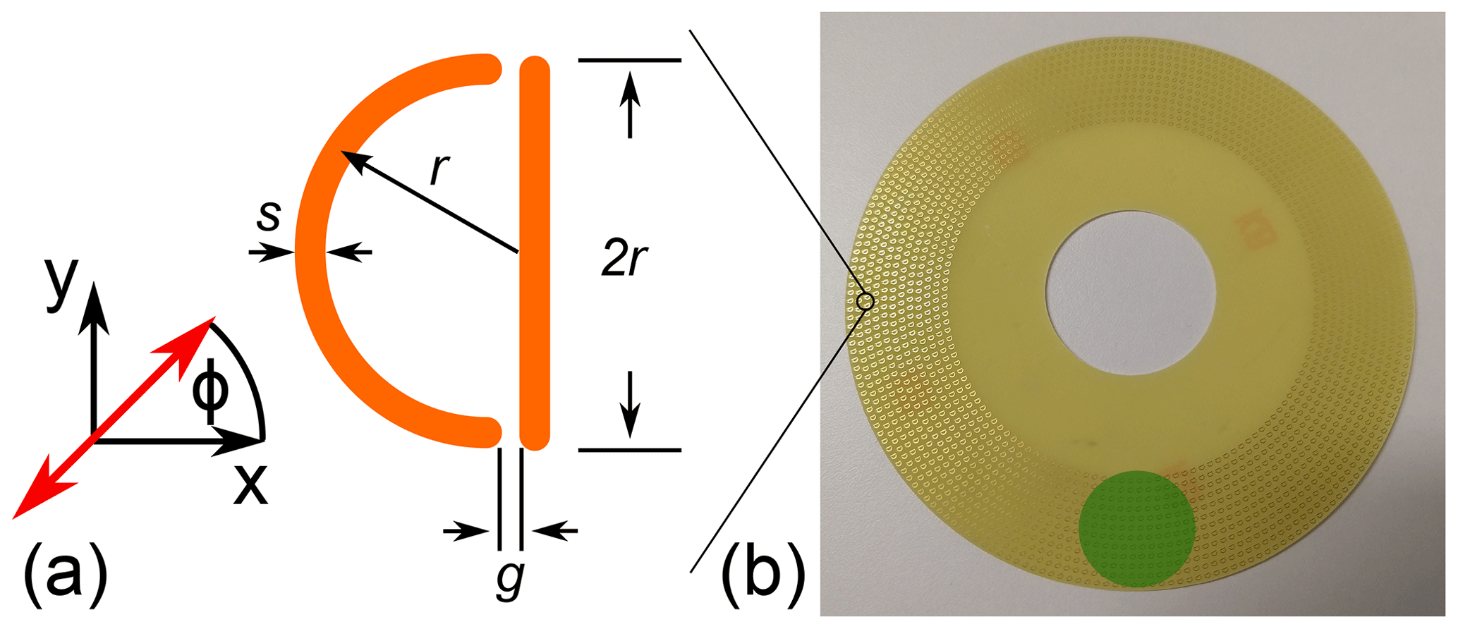
Figure 1Metamaterial. (a) Sketch of the unit cell. (b) Array on the FR4 disc. The green circle marks the area illuminated by the millimeter waves.
In this section, we derive that it is possible to manufacture metamaterials with resonance frequencies in the millimeter wave regime using state-of-the-art PCB manufacturing methods. We calculate the resonance frequency from the effective wavelength of the currents on the metamaterial structures. The currents on metamaterials at their characteristic resonances form standing waves on the conductive structures. A sketch of the current and charge distribution of our metamaterial in the Fano-type resonant mode is shown in Fig. 2.
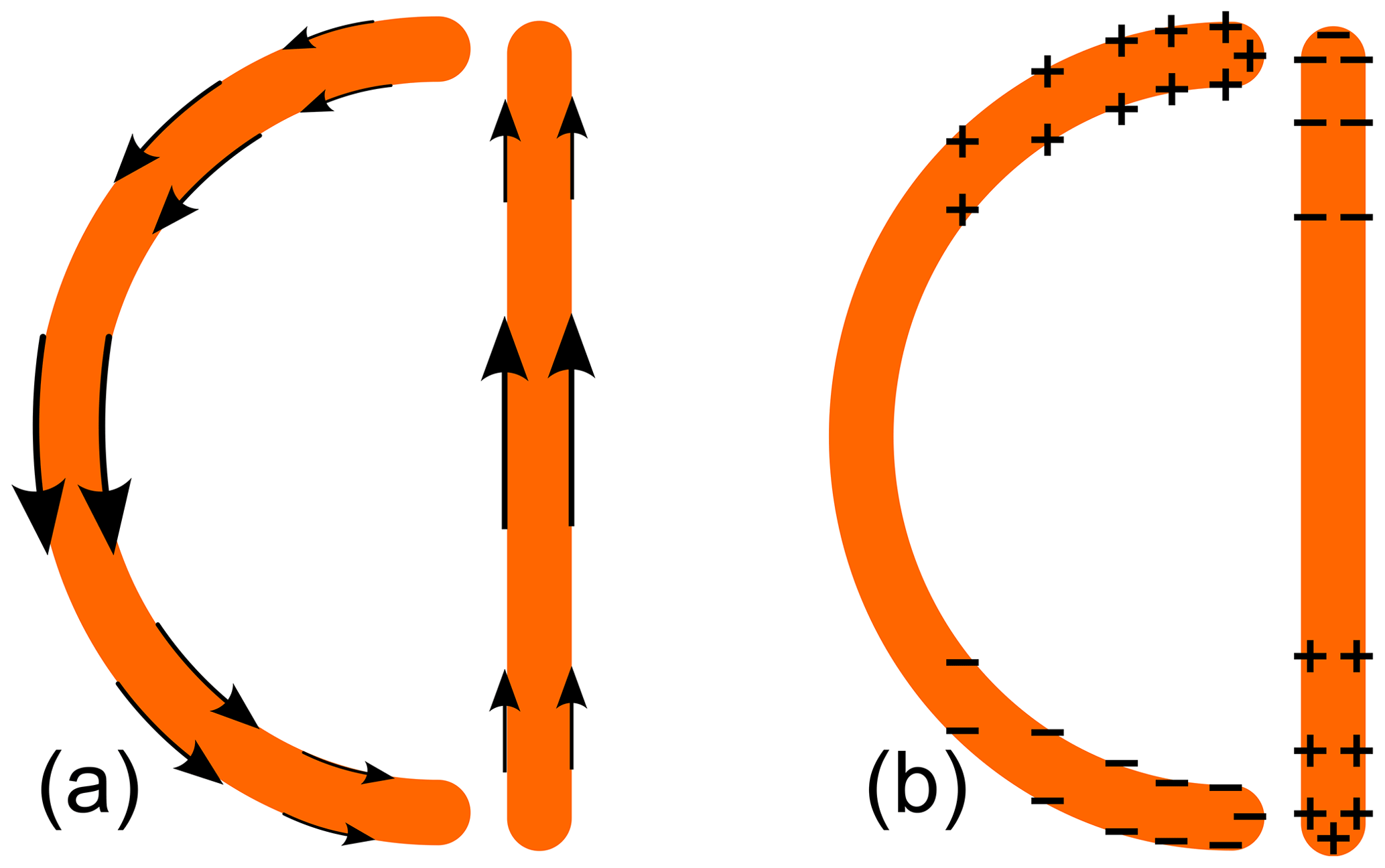
The current runs circularly on the copper structures, meaning that the current direction on the vertical slab is opposite to that on the arc. In principle, a standing wave can occur on both the arc and the vertical line, leading to electric dipole-like and magnetic dipole-like resonances. The Fano-type resonance occurs when half the wavelength corresponds to the arc length, and simultaneously the current on the vertical line flows in the opposite direction (Fedotov et al., 2007), corresponding to a magnetic dipole-like resonance. We calculate an approximation of the resonance frequency according to considering that, for the standing wave on the arc, equals the arc length:
with ceff the effective speed of the current signals given by
and c0 the speed of light in vacuum and ϵeff the effective dielectric constant. The copper structures of our metamaterial are printed on top of the substrate, and thus parts of the fields go through the substrate and parts go through the air. We approximate ϵeff as the effective dielectric constant of coupled strip lines, whereby in the metamaterial the capacitive coupling takes place between the edges of the vertical line and the arc in Fig. 2. Following Gevorgian and Berg (2001), the effective dielectric constant is given as
with K the complete elliptic integral of the first kind and
and . The prime index means . h is the substrate thickness. The gap g and line width s are sketched in Fig. 1. We first benchmark the presented model with results in Fedotov et al. (2007). We put the geometrical parameters of the arc length, gap and material parameters of the substrate as specified in Fedotov et al. (2007) in Fig. 1, which gives a resonance frequency of 6.4 GHz. This is in good agreement with the experimental result in Fedotov et al. (2007) that showed for the Fano type a resonance frequency close to 6 GHz. Equation (1) shows that the resonance frequency is indirectly proportional to the arc length of our metamaterial. Thus, the highest achievable resonance frequency is determined by the smallest manufacturable metamaterial unit cell. According to state-of-the-art manufacturers, the minimum line width with s is 100 µm and the minimum space between the copper lines g is 100 µm, given a copper layer thickness of 35 µm (Multi Circuit Boards Ltd., 2023; Elgoline d.o.o., 2023). With these values the minimum radius of curvature r is 200 µm. Putting these values into Eq. (1) gives a resonance frequency of 146 GHz, which is in the mid-millimeter wave range. Thus, based on our analytical model, it is possible to manufacture metamaterials with Fano-type resonances for frequencies in the millimeter wave regime using standard PCB manufacturing methods. Furthermore, our simple analytical model allows us to approximate the geometrical parameters of the metamaterial for a desired resonance frequency with good accuracy. The millimeter wave chip we use in the experiment shown in Chap. 5.1.1 has a working frequency of about 60 GHz. Transforming Eq. (1) to
gives a radius of 0.49 mm for a desired resonance frequency of 60 GHz. We use this value as a starting point for the finite-element method analysis in the subsequent chapter. More elaborate studies on the resonant behavior are based on equivalent circuit models that require us to calculate the inductive and capacitive terms at resonance. However, to the best of our knowledge, there is no analytic approach for calculating the capacitive coupling between an arc and a vertical line as in our metamaterial. These capacitances can be calculated with numerical methods. Our semi-analytic model gives the relation between resonance frequency and unit cell size without the need for elaborate finite-element calculations and with reasonable accuracy. We use finite-element methods to directly study the resonant behavior. We use the results to get precise values for the geometrical parameters of the metamaterial that are used for manufacturing. Furthermore, we calculate reflection spectra which can be compared to measurement results of reflection spectra.
We conduct finite-element calculations of the metamaterial in order to analyze the resonant behavior. We implement a 3D model of one square unit cell with periodic boundary conditions as sketched in Fig. 3.
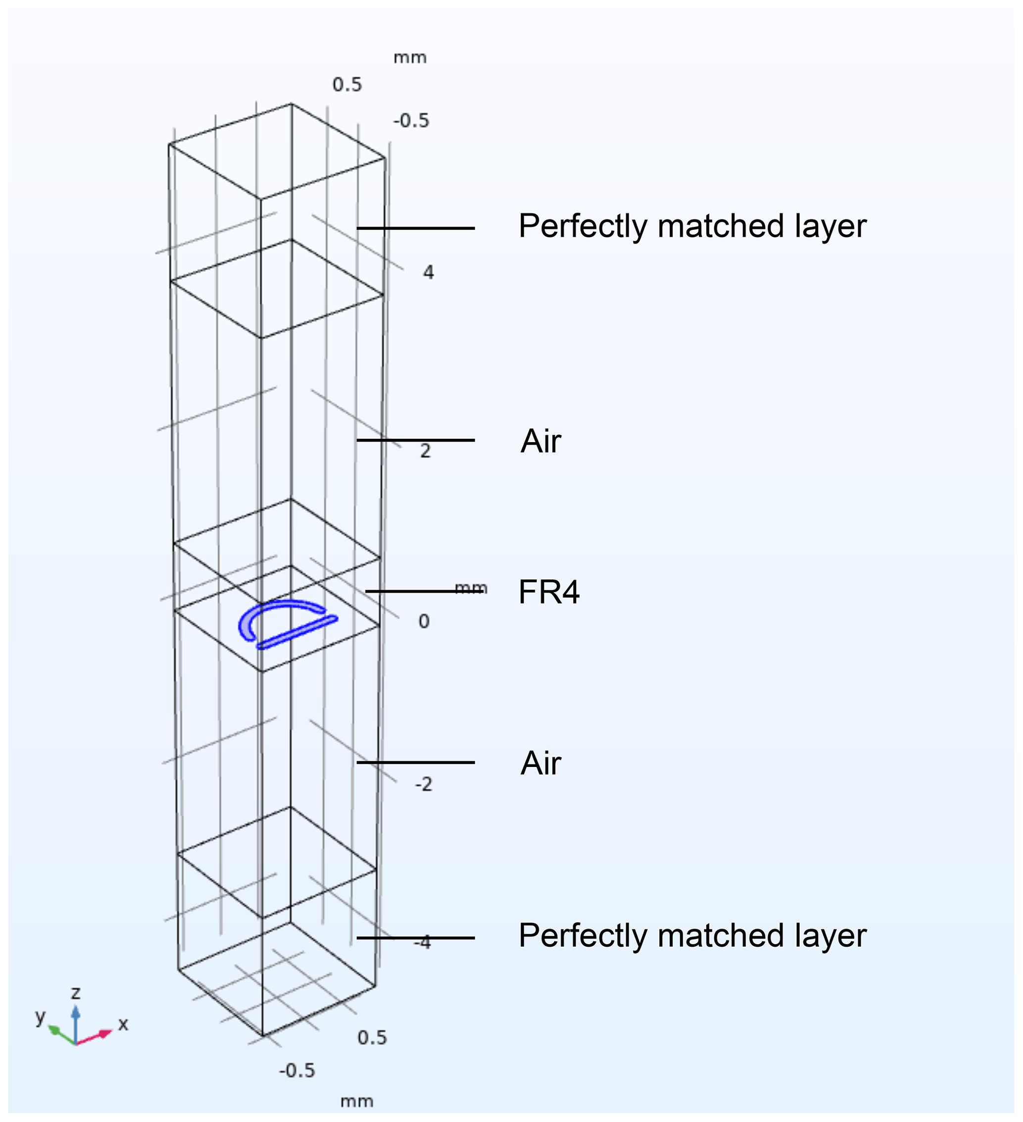
Figure 3Three-dimensional model of the unit cell as simulated in COMSOL Multiphysics®. The metamaterial structure is highlighted in blue.
We implement the plane wave incidence of linearly polarized electromagnetic waves from a port boundary on top of the geometry with a perfectly matched layer in its background. Plane wave incidence is justified considering that the size of the on-chip patch antenna is (2×1) mm and the measurement distance is 2.7 cm. At the working frequency of the chip of about 60 GHz, the Fraunhofer distance, according to
is then 2.5 mm. In our sensor setup, as explained in Chap. 5.1.1, the measurement distance is 3 cm, and thus we are in the far-field region where the plane wave approximation holds. We choose Panasonic R-1755M laminates with a thickness of 0.8 mm as a substrate. We extrapolate the material properties for the dielectric constant from the values given in the data sheet of the manufacturer. In a first step, we calculate the eigenfrequencies of the unit cell with the given boundary conditions. We perform a parameter study of the geometrical parameters in order to obtain a resonance frequency at 60 GHz. We vary two parameters: the length of the straight line and the unit cell size. The radius of the semi-circle is set to half the length of the straight line. The line width of the semi-circle and straight line and the gap between them are set to 100 µm, which is in accordance with standard PCB manufacturing methods. The result of our parameter study is a line length of 1 mm and a unit cell side length of 1.5 mm. With these parameters we calculate the spectrum of the scattering parameter S11 at the port as a function of the angle φ between the electric field polarization and the x axis in Fig. 3. S11 is defined as the ratio of traveling wave voltages of transmitted and reflected planar waves at the port, which corresponds to the reflection coefficient.
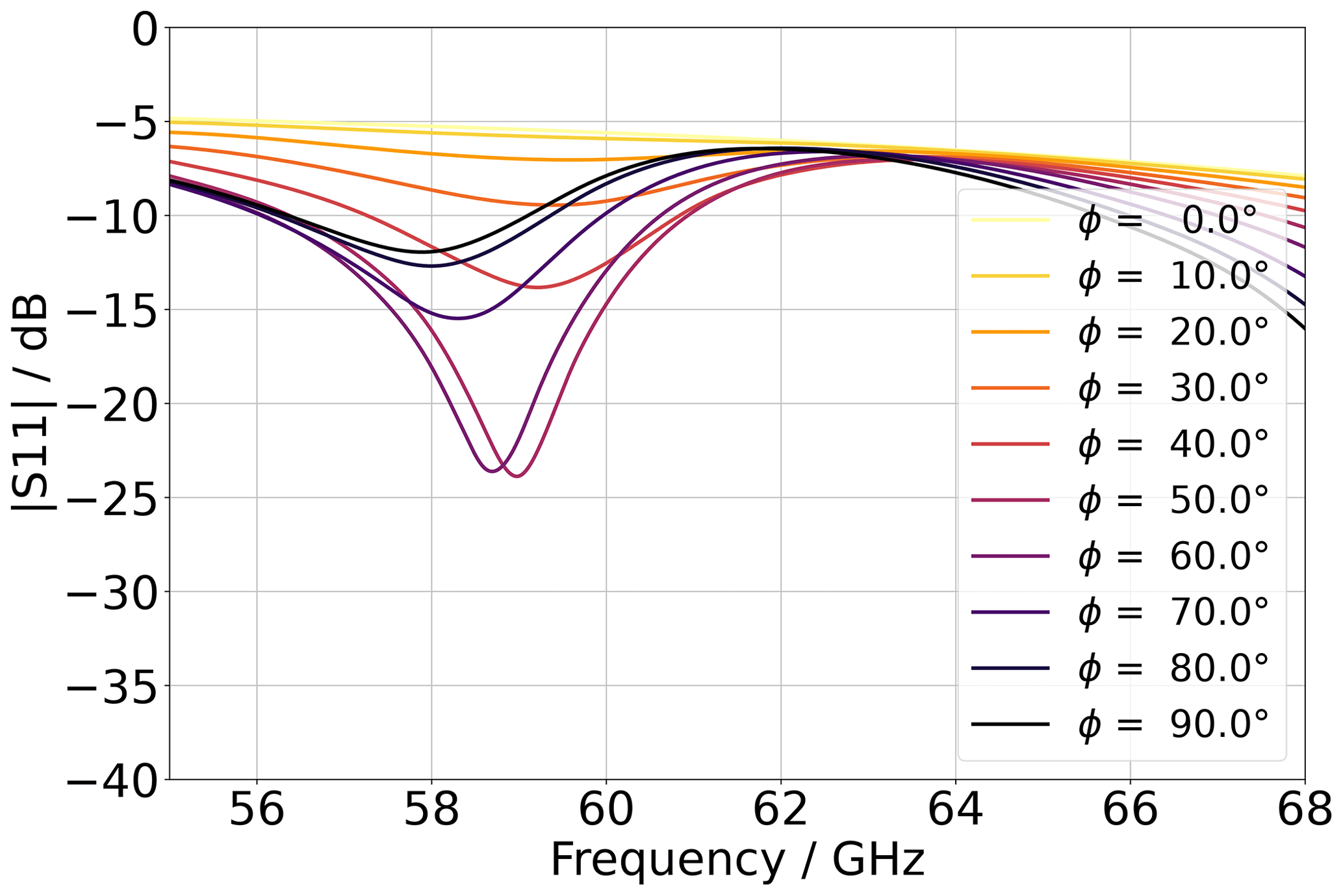
Figure 4Simulated S11 spectra for various angles φ between the electric field polarization and the x axis in Fig. 3.
Results are shown in Fig. 4 for φ in the range between 0 and 90°. Due to the symmetry of the unit cell, the curves in the range from 90 to 180° overlap with those from 0 to 90°. The curve for φ= 50° shows a distinct minimum. This minimum in reflection comes from the resonant behavior of the metamaterial. At resonance, the coupling from the incident electromagnetic waves to the fields in the metamaterial plane is maximum. The fields in the metamaterial unit cells at the Fano resonance correspond to a magnetic dipole with orientation perpendicular to the metamaterial plane. Thus, it does not radiate perpendicularly to the metamaterial plane, and therefore at resonance the fields are mainly scattered in directions parallel to the plane. Further, the current density on the copper structures is also maximum at resonance, which in turn maximizes the ohmic losses. These two effects lead to a minimum in the reflection spectra at the resonance frequency. The data in Fig. 4 show that the minimum is most pronounced at φ=50°, which indicates that the coupling to the Fano-resonance mode is strongest for that angle. Most importantly, the data show that varying φ significantly changes the shape of the minimum of the spectra in Fig. 4, which corresponds to a significant change in the reflectance close to the resonance frequency. Our proposed sensor effect is based precisely on this behavior. The idea is to measure the change in reflectance as a function of the rotation angle φ with a millimeter wave chip.
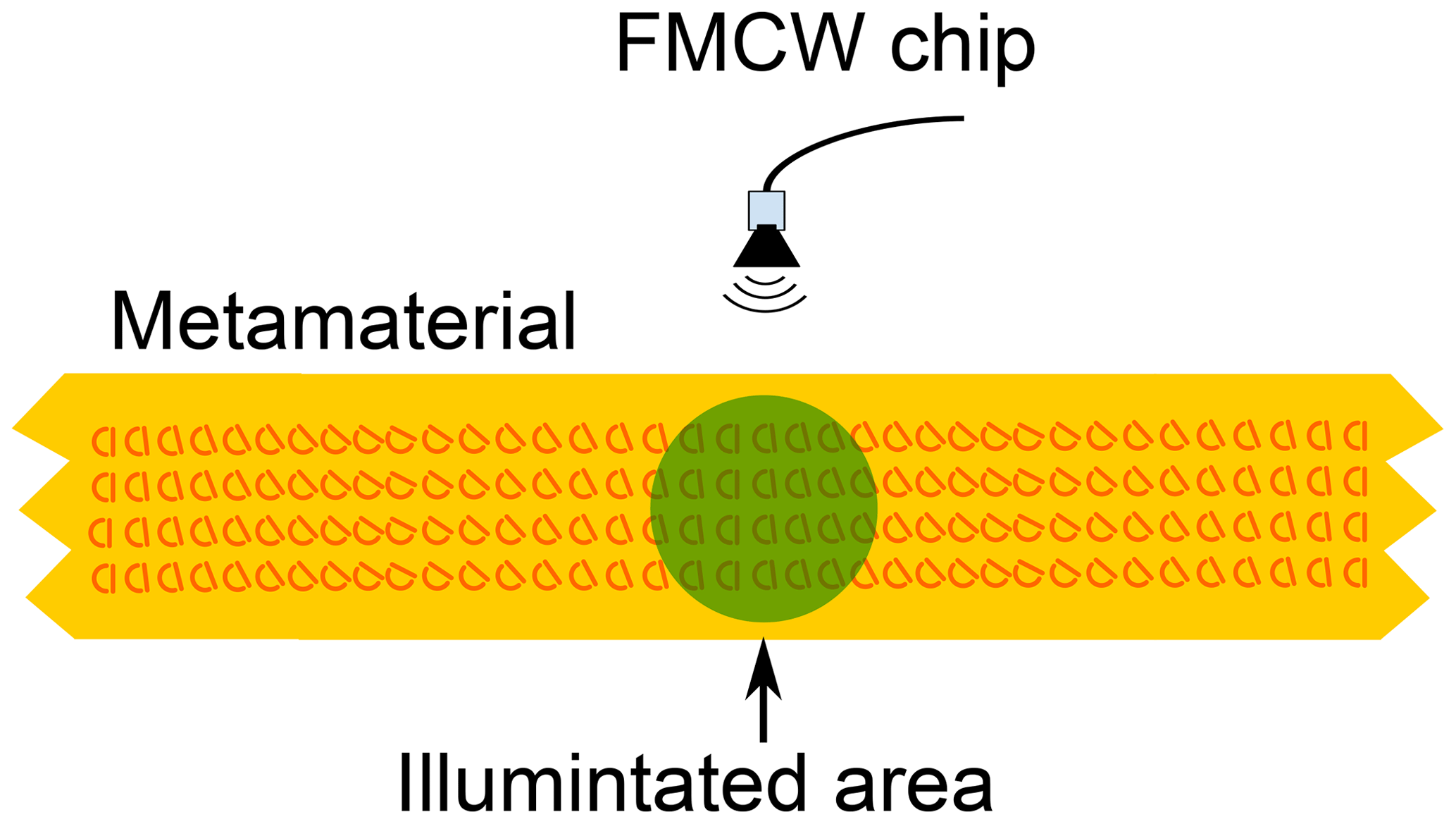
The metamaterial is manufactured as a single layer of unit cells on a disc with a diameter of 10 cm. The unit cells are arranged in a circular pattern as shown in Fig. 1. All the unit cells are aligned parallel to each other, meaning that the vertical lines of all the unit cells are pointing in the same direction. The measurement setup is done in an off-axis setup with the antenna irradiating a small area of the metamaterial array, indicated exemplarily with a green circle in Fig. 1. With the antenna fixed and the metamaterial disc rotating, the unit cells are effectively changing their orientation within the area irradiated by the millimeter waves. In our experimental setup the metamaterial disc is mounted on an aluminum axis with turned aluminum holders. The FMCW chip and the horn antenna are mounted on opposite sides of the disc. A picture of the setup is shown in Fig. 5.
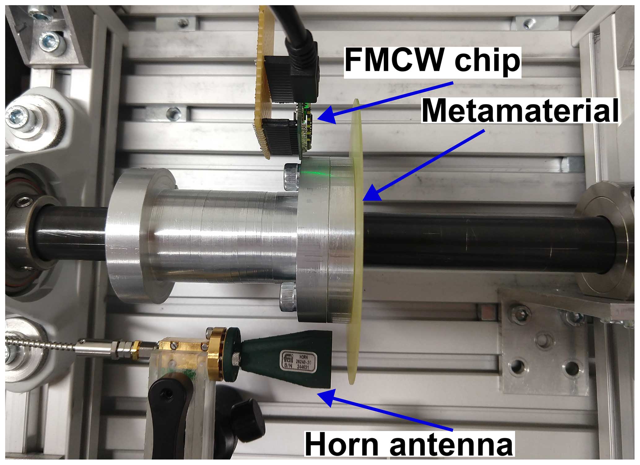
This allows us to measure simultaneously with the FMCW chip and the horn antenna. A degree disc is further fixed to the shaft for reading of the angle, which is not shown in Fig. 5.
5.1 Measurement with a vector network analyzer
We use an Anritsu MS4647B vector network analyzer that is connected to a 20 dB waveguide horn antenna with a coaxial-to-waveguide adapter. The measurement distance between the metamaterial and the antenna is 1 cm. We record S11 spectra for rotation angles φ in the range between 0 and 90°. Prior to the measurements, we perform a short;offset-short;match waveguide calibration at the connection between the adapter and the antenna. In a postprocessing step, we perform time domain gating of the data to take into account that the horn antenna is not considered in the calibration. The results of the S11-parameter spectra are shown in Fig. 6.
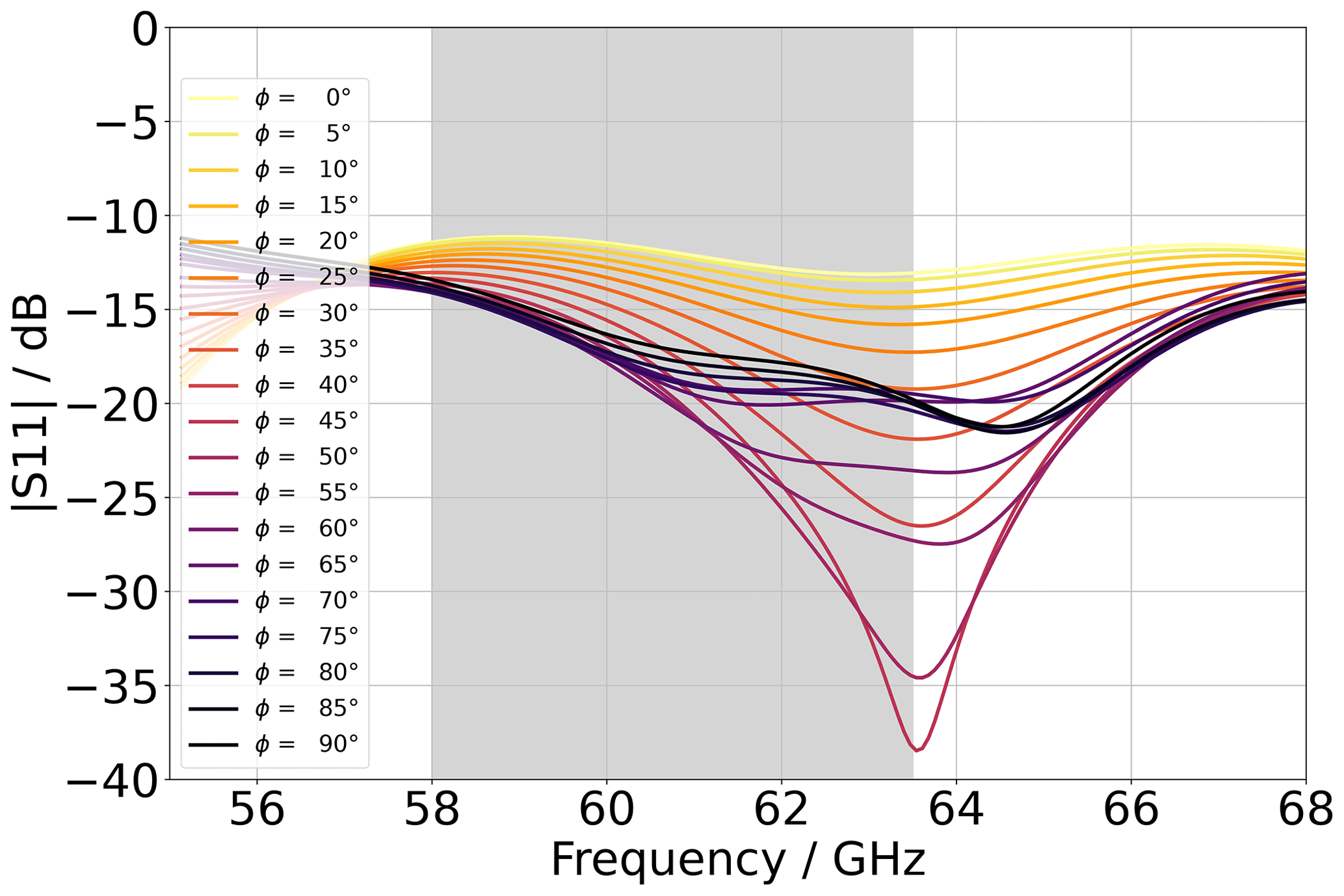
Figure 6Measured S11 spectra for various rotation angles φ. The grey area highlights the frequency range of the FMCW chip.
The data in Fig. 6 show good accordance with the simulated spectra in Fig. 4. As in the simulated data, the experimental data show characteristic minima in the S11 spectra. The minimum is most pronounced for φ=55°, which is also the case for the simulated data. Further, the experiment shows the desired dependency of the reflectance of the rotation angle φ within the frequency bandwidth of the FMCW chip. There is an overall horizontal shift of the minima in Fig. 6 compared to the simulation results, which we explain by the fact that the value of the dielectric constant of the laminate is smaller than the value we obtained from extrapolation of the data sheet and put into the simulation. Nevertheless, the measured curves show the proposed sensor effect within the bandwidth of the FMCW chip, highlighted in grey in Fig. 6.
5.1.1 Measurement with the FMCW chip
We installed the FMCW chip at a distance of 2.7 cm to the metamaterial as shown in Fig. 5. We choose this distance due to the fact that the minimum measurement distance of a FMCW chip is given as
with B the chirp bandwidth and c the speed of light. The FMCW chip provided by Infineon has a chirp bandwidth of 5.5 GHz, which gives dmin=2.7 cm. The chip is mounted on a test-kit baseboard provided by Infineon. We calculated the amplitude fast Fourier transform (FFT) spectra using the on-chip FFT routine and record them with a PC that is connected to the baseboard via a USB cable. The on-chip routine includes an offset compensation of the raw data as well as windowing using a Hamming window to reduce leakage effects. The read-out rate in our experimental setup is set to 50 Hz. However, state-of-the-art FMCW chips have chip repetition times on the order of microseconds, which corresponds to read-out rates on the order of megahertz. Results of the recorded FMCW chip FFT spectra are shown in Fig. 7.
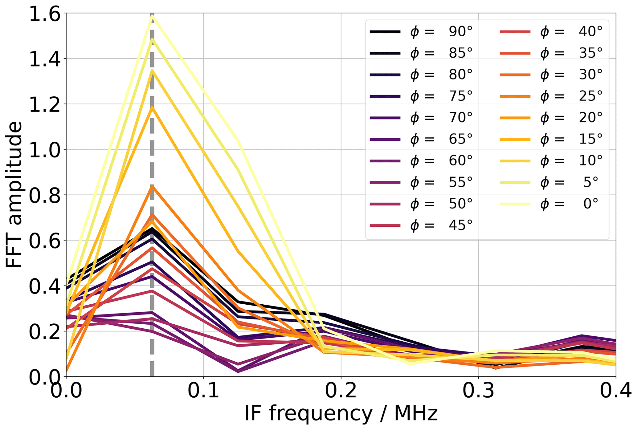
Figure 7FFT spectra measured with the FMCW millimeter wave chip. The grey dashed line marks the peak that comes from the reflection of the metamaterial target.
The first peak in Fig. 7, marked with a grey dashed line, corresponds to the reflection from the metamaterial. The FMCW data of the FFT peak are proportional to the area under the reflection curves within the FMCW chip bandwidth in Fig. 6. The data in Fig. 7 show that the value of the FFT amplitude at the grey dashed line significantly depends on the rotation angle φ. In Fig. 8 we plot the amplitude at the grey dashed line as a function of the rotational angle φ.
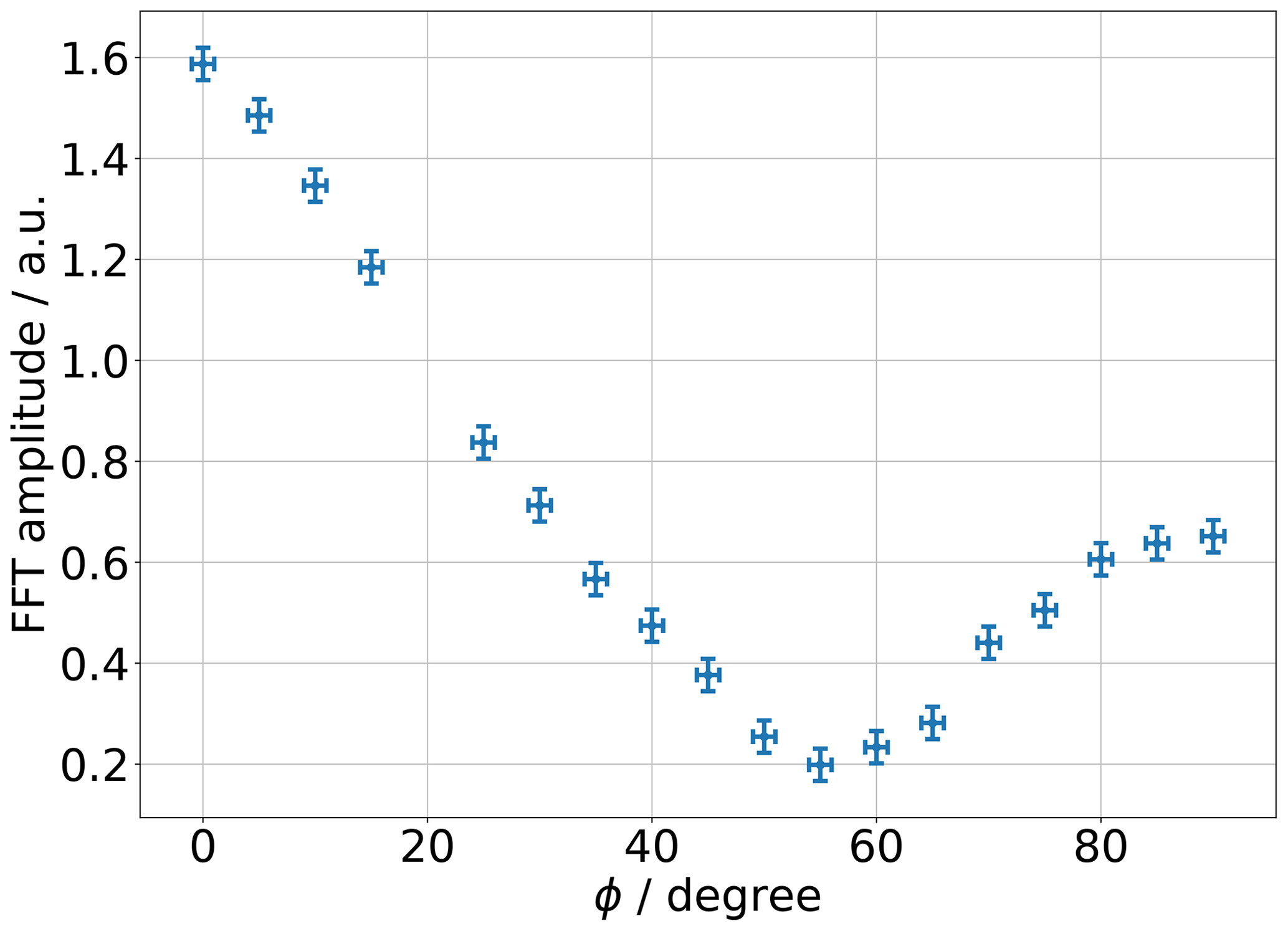
Figure 8Amplitude of the FFT spectrum at the grey dashed line in Fig. 7. The horizontal error bars correspond to the estimated reading uncertainty, and the vertical error bars correspond to the 1σ uncertainty of the FFT amplitude.
The horizontal error bars show the estimated reading error of the degree disc in the experiment. For the estimation of the vertical error bars, we installed a PCB disc without metamaterial structures, rotated it by the same values of φ as in the experiment, and calculated the standard deviation of the FFT amplitude. The data in Fig. 8 show that for φ=0° the amplitude at the reflection peak has the largest value and that for φ=55° the amplitude has the smallest value. This is in accordance with the reflection spectra in Fig. 6 and confirms that the FFT amplitude at the corresponding peak is proportional to the integrated reflectivity curve within the FMCW chip bandwidth. For φ>55° the FFT amplitude increases with increasing φ, which is in accordance with an increase in the reflectivity in the measured and simulated spectra of Figs. 6 and 4. Our experiment shows that the FFT amplitude is a bijective function of the rotation angle φ in the range between 0 and 55°. Based on these results, it is straightforward to implement a rotary encoder with our proposed concept by simply manufacturing the orientation of the metamaterial unit cell in the way it is needed. The orientation of the unit cell in the circular metamaterial array in Fig. 1b) is varied along the circumference such that the angle between the vertical line of the unit cells and the radial unit vector of the disc's polar coordinates varies between 0 and 55°. In this way, the concept is analogous to state-of-the-art rotary encoders that encode the angle information using orientations of magnetized areas or barcode-like structures. In our proposed sensor concept the angle information is encoded in the orientation of the metamaterial unit cells within their array. An example for implementing an absolute rotary encoder is to manufacture the unit cells such that their angle to the radial unit vector of the disc varies from 0 to 55° along one full circumference of the circular array. With the disc rotating, the angle between the unit cell vertical lines and the polarization of the millimeter waves then periodically changes between 0 and 55° and gives a bijective correspondence between the rotational angle and the FFT amplitude of the FMCW chip. From the uncertainty estimation of our experiment, we obtain an accuracy of 1.27° in the range between 0 and 55°. We point out that this value of accuracy is an estimation based on the first principle measurement performed in this work. Minimizing multipath interferences and avoiding parasitic reflections from metallic components of our laboratory setup is expected to increase the signal quality significantly. This can be achieved with absorptive claddings or by increasing the gain of the transmitter antenna, which corresponds to a reduction of the beam angle. With these measures, we expect an increase in the accuracy of 1 order of magnitude, corresponding to approximately 0.1° in the above setup. A further significant increase in the accuracy involves an initial calibration of the FFT amplitude curve. A decisive advantage of the metamaterial-based concept is that the shape of the function of the FFT amplitude curve can be chosen by systematically varying the angle φ along the circumference of the manufactured metamaterial array. This is particularly advantageous for implementing interpolation algorithms in the evaluation electronics. In principle, the resolution of this concept can be increased by a factor of N by arranging the unit cells such that, for one revolution of the disc, the unit cells are N times varied between 0 and 55°. The resolution depends on the periodic amplitude curve systematically imprinted by a metamaterial array. This is analogous to optical encoders, where systematic variations between opaque and transparent regions define the reflection amplitude curve. In our sensor concept, the minimum area where the angles of the metamaterial unit cells can be varied is given by the spot size of the area illuminated by the millimeter wave transmitter. Assuming a patch antenna with low directivity, as with the BGT60TR13C chip, and a distance between the transmitter and metamaterial array of 5 mm gives a spot size of approximately 20 mm. We estimate that a sufficient range of the FFT amplitude is achieved when the array is moved by one spot size. This gives for our laboratory setup an accuracy of ±0.23 mm. For an accuracy of 0.1° for φ that we assumed for a setup with absorptive claddings or optimized antenna gain, the estimated spatial accuracy is then ±0.018 mm. The main influence of temperature on the sensor effect is the change in resonance frequency due to a change in the relative permittivity of the PCB substrate with temperature. The temperature-induced change in the resistivity of the copper structures plays a minor role since the main contributions to the absorption in the millimeter wave frequency regime are the loss factor of the substrate, the surface roughness of the copper structures, and radiative losses. The literature showed for similar FR4 circuit board laminates that the relative change in permittivity in the temperature range between 20 and 100 °C is on the order of 5 % (Hinaga et al., 2010; Heinola et al., 2004). The manufacturer of a ceramic-based high-frequency laminate quotes a maximum relative change of 0.8 % in the temperature range between −50 and 150 °C (Rogers corporation, 2022). Thus, for the implementation of a high-resolution encoder, a temperature compensation is required. This can be implemented straightforwardly using an additional metamaterial array where the angle φ does not change with the rotation of the measurement object and by measuring the relative shift between the array with fixed φ and varying φ. Furthermore, combining multiple traces of metamaterial circular arrays with a parallel read-out allows an absolute sine–cosine encoder to be implemented. The implementation of linear position sensing is straightforward: the metamaterial unit cell array is manufactured as a linear trace along the measurement object with the position information encoded in the tilt angle of the metamaterial unit cells. A sketch is shown in Fig. 9.
We showed a sensor concept for fully telemetric angle and position measurement based on single-layer millimeter wave metamaterials. The sensor effect is based on the anisotropy of the characteristic Fano-type resonant behavior of the metamaterial. We presented a simple analytical approximation for the characteristic resonance frequency of the metamaterial, which estimates that standard manufacturing methods are usable for the fabrication of the metamaterial targets with resonance frequencies in the millimeter wave regime. We provided a detailed analysis of the sensor effect by means of finite-element method calculations and measurement of scattering parameters using a vector network analyzer. The numerical and experimental results agree well, thus showing that our fabricated metamaterial exhibits the desired resonant behavior. Furthermore, we provided a proof of concept using a state-of-the-art FMCW chip with a working frequency of about 60 GHz. We point out that the proposed sensor concept is not limited to this frequency regime. Due to the fact that metamaterials obtain the characteristic properties through their geometrical parameters, they are inherently highly scalable and therefore limited only by manufacturing capabilities. We are confident that our proposed sensor concept potentially paves the way toward a new angle and position sensor technology based on resonant metamaterials.
Data sets are made available on request.
Conceptualization: AS and AB; methodology: AS; investigation: AS, MT; formal analysis: AS, MT, CS; writing – original draft preparation: AS; writing – review and editing: AS, MT, CS, and AB; supervision: AB.
At least one of the (co-)authors is a member of the editorial board of Journal of Sensors and Sensor Systems. The peer-review process was guided by an independent editor, and the authors also have no other competing interests to declare.
Publisher’s note: Copernicus Publications remains neutral with regard to jurisdictional claims made in the text, published maps, institutional affiliations, or any other geographical representation in this paper. While Copernicus Publications makes every effort to include appropriate place names, the final responsibility lies with the authors.
This article is part of the special issue “Sensors and Measurement Science International SMSI 2023”. It is a result of the 2023 Sensor and Measurement Science International (SMSI) Conference, Nuremberg, Germany, 8–11 May 2023.
The financial support by the Austrian Federal Ministry for Digital and Economic Affairs; the National Foundation for Research, Technology and Development; and the Christian Doppler Research Association is gratefully acknowledged.
This research has been supported by the Christian Doppler Forschungsgesellschaft (Christian Doppler Laboratory for Structured Matter Based Sensing grant).
This paper was edited by Marco Jose da Silva and reviewed by two anonymous referees.
Rogers corporation: RO4350B™ Laminates, https://rogerscorp.com/advanced-electronics-solutions/ro4000-series-laminates/ro4350b-laminates (last access: December 2022), 2022. a
Infineon Radar Sensors: BGT60TR13C, https://www.infineon.com/cms/de/product/sensor/radar-sensors/radar-sensors-for-iot/60ghz-radar/bgt60tr13c/ (last access: September 2023), 2023. a
Elgoline d.o.o.: Technical Capabilities of PCB, https://en.elgoline.si/technical-capabilities (last access: September 2023), 2023. a
Multi Circuit Boards Ltd.: Platinendesign-Hilfe: Einführung, https://www.multi-circuit-boards.eu/leiterplatten-design-hilfe/einfuehrung.html (last access: September 2023), 2023. a
Alejandre, I. and Artés, M.: Method for the evaluation of optical encoders performance under vibration, Precis. Eng., 31, 114–121, https://doi.org/10.1016/j.precisioneng.2006.03.004, 2007. a
Buriak, I. A., Zhurba, V. O., Vorobjov, G. S., Kulizhko, V. R., Kononov, O. K., and Rybalko, O.: Metamaterials: Theory, classification and application strategies (review), J. Nanoelectron. Phys., 8, 4088, https://doi.org/10.21272/jnep.8(4(2)).04088, 2016. a
Chuang, H. C., Kung, C. W., Chen, L. W., and Jiang, S. B.: Nonlinear Error Correction for Magnetic Encoders, IEEE Sens. J., 23, 9129–9135, https://doi.org/10.1109/JSEN.2022.3214575, 2023. a
Ellin, A. and Dolsak, G.: The design and application of rotary encoders, Sensor Rev., 28, 150–158, https://doi.org/10.1108/02602280810856723, 2008. a
Fedotov, V. A., Rose, M., Prosvirnin, S. L., Papasimakis, N., and Zheludev, N. I.: Sharp Trapped-Mode Resonances in Planar Metamaterials with a Broken Structural Symmetry, Phys. Rev. Lett., 99, 147401–147405, https://doi.org/10.1103/PhysRevLett.99.147401, 2007. a, b, c, d, e, f
Fleming, W. J.: Overview of Automotive Sensors, IEEE Sens. J., 1, 296–308, https://doi.org/10.1109/7361.983469, 2001. a
Gevorgian, S. and Berg, H.: Line capacitance and impedance of coplanar-strip waveguides on substrates with multiple dielectric layers, http://amsacta.unibo.it/393/1/Eug_p114.pdf (last access: December 2023), 2001. a
Hao, S., Liu, Y., and Hao, M.: Study on a Novel Absolute Magnetic Encoder, IEEE Xplore, 2008 IEEE International Conference on Robotics and Biomimetics, 22–25 February 2009, Bangkok, https://doi.org/10.1109/ROBIO.2009.4913270, 2009. a, b
Heinola, J., Latti, K., Silventoinen, P., Strom, J.-P., and Kettunen, M.: A new method to measure dielectric constant and dissipation factor of printed circuit board laminate material in function of temperature and frequency, IEEE Xplore 9th International Symposium on Advanced Packaging Materials, https://ieeexplore.ieee.org/abstract/document/1288019/ (last access: December 2023), 2004. a
Koledintseva, M. Y., Drewniak, J. L., Koul, A., and Zhou, F.: Thermal effects on PCB laminate material dielectric constant and dissipation factor, IPC APEX EXPO, https://www.ipc.org/system/files/technical_resource/E7%26S16_01.pdf (last access: December 2023), 2010. a
Javaid, M., Haleem, A., Singh, R. P., Rab, S., and Suman, R.: Significance of sensors for industry 4.0: Roles, capabilities, and applications, Sensors Int., 2, 100110, https://doi.org/10.1016/j.sintl.2021.100110, 2021. a
Kumar, A. S., George, B., and Mukhopadhyay, S. C.: Technologies and Applications of Angle Sensors: A Review, IEEE Sens. J., 21, 7195–7206, https://doi.org/10.1109/JSEN.2020.3045461, 2021. a
Lenz, J. and Edelstein, S.: Magnetic sensors and their applications, IEEE Sens. J., 6, 631–649, https://doi.org/10.1109/JSEN.2006.874493, 2006. a, b
López, J., Artés, M., and Alejandre, I.: Analysis of optical linear encoders' errors under vibration at different mounting conditions, Measurement, 44, 1367–1380, https://doi.org/10.1016/J.MEASUREMENT.2011.05.004, 2011. a
Max, S., Vossiek, M., and Gulden, P.: Fusion of FMCW secondary radar signal beat frequency and phase estimations for high precision distance measurement, 2008 European Radar Conference, 30-31 October 2008, Amsterdam, https://ieeexplore.ieee.org/abstract/document/4760817/ (last access: December 2023), 2009. a
Nyce, D. S.: Linear position sensors: theory and application, Linear Position sensors: Theory and Application, John Wiley & Sons, ISBN 3175723993, 2004. a
Prelle, C., Lamarque, F., and Revel, P.: Reflective optical sensor for long-range and high-resolution displacements, Sensor. Actuat. A-Phys., 127, 139–146, https://doi.org/10.1016/J.SNA.2005.11.005, 2006. a
Ripka, P. and Janosek, M.: Advances in Magnetic Field Sensors, IEEE Sens. J., 10, 1108–1116, https://doi.org/10.1109/JSEN.2010.2043429, 2010. a
Ruocco, S. R.: Position transducers, Robot sensors and transducers, Springer, 12–26 pp., https://doi.org/10.1007/978-94-011-6870-0_2, 1987. a
Singh, R., Al-Naib, I. A. I., Koch, M., and Zhang, W.: Sharp Fano resonances in THz metamaterials, Opt. Express, 19, 6312–6319, https://opg.optica.org/abstract.cfm?uri=oe-19-7-6312 (last access: December 2023), 2011. a
Tuz, V. R., Wang, H., Domina, K. L., Sun, H.-B., Kupriianov, A. S., Khardikov, V. V., and Xu, S.: High-quality trapped modes in all-dielectric metamaterials, Opt. Express, 26, 2905–2916, https://doi.org/10.1364/OE.26.002905, 2018. a
Yan, J. C., Li, Z. K., Zhang, Y., Wang, Y. L., and Huang, C. P.: Trapped-mode resonances in all-metallic metasurfaces comprising rectangular-hole dimers with broken symmetry, J. Appl. Phys., 126, 21, https://doi.org/10.1063/1.5128520, 2019. a
Yang, S., Liu, Z., Xia, X., Yiwen, E., Tang, C., Wang, Y., Li, J., Wang, L., and Gu, C.: Excitation of ultrasharp trapped-mode resonances in mirror-symmetric metamaterials, Phys. Rev. B, 93, 1–8, https://doi.org/10.1103/PhysRevB.93.235407, 2016. a
Yu, H., Chen, X., Liu, C., Cai, G., and Wang, W.: A survey on the grating based optical position encoder, Opt. Laser Technol., 143, 107352, https://doi.org/10.1016/j.optlastec.2021.107352, 2021. a
Zheng, C., Zhu, K., Cardoso de Freitas, S., Chang, J.-Y., Davies, J. E., Eames, P., Freitas, P. P., Kazakova, O., Kim, C., Leung, C.-W., Liou, S.-H., Ognev, A., Piramanayagam, S. N., Ripka, P., Samardak, A., Shin, K.-H., Tong, S.-Y., Tung, M.-J., Wang, S. X., Xue, S., Yin, X., and Pong, P. W. T.: Magnetoresistive sensor development roadmap (non-recording applications), IEEE T. Magn., 55.4, 1–30, https://doi.org/10.1109/TMAG.2019.2896036), 2019. a
Zouhdi, S., Sihvola, A., and Arsalane, M.: Advances in Electromagnetics of Complex Media and Metamaterials, Nato Sci. Ser. II Math., Kluwer Academic Publishers, The Netherlands, 2003, 89, 281–290, https://doi.org/10.1007/978-94-007-1067-2, 2002. a