the Creative Commons Attribution 4.0 License.
the Creative Commons Attribution 4.0 License.
 | 06 Aug 2025
The optimal planform of a cantilever unimorph piezoelectric vibrating energy harvester (PVEH) with a device-layer edge block
Eliya Salman
Sahar Lustig
The study considers the optimal planform of a cantilever piezoelectric vibrating energy harvester (PVEH) with an edge block that is patterned only in the device layer. The optimal response of a PVEH is achieved when the strain in the piezoelectric layer is uniform. It is possible to design the planform of the PVEH such that when it vibrates at a given frequency of excitation vibrations, the mode shape results in a uniform strain in the piezoelectric layer. Another design choice is the size of the edge block. The size of the edge block affects the natural frequency of the structure and hence may be adjusted such that the natural frequency of the PVEH matches the frequency of the excitation vibrations. Previous studies considered the optimal planform of a PVEH with a massive edge block that is patterned in both the device and handle layers of the wafer. For this case, it was found that the optimal planform of such a device is trapezoidal. However, there is another class of PVEH devices in which the edge block is patterned only in the device layer (i.e., a device-layer edge block). In the present study, we show that the optimal planform for such a PVEH is defined by Bessel functions, and we demonstrate the predictive capabilities of our analytic model by comparison to results of finite-element simulations.
- Article
(1418 KB) - Full-text XML
- Companion paper
- BibTeX
- EndNote


Piezoelectric vibrating energy harvester (PVEH) devices have been extensively studied because of their potential to power autonomous sensors. The design of such devices varies extensively depending on the frequency distribution of the environmental vibrations. The simplest case is when the frequency of the environmental vibrations is fixed and a priori known. In this case, it is possible to optimize a cantilever PVEH such that its natural frequency is compatible with the excitation vibrations. In the context of PVEHs that target a specific excitation frequency, it is often assumed that the optimal performance is achieved when the strain amplitude in the piezoelectric layer is uniform (Salman et al., 2024b, 2025).
In typical cantilever PVEH devices that are made using silicon-on-insulator (SOI) wafer technology (Cowen et al., 2014; Du et al., 2017; Jia and Seshia, 2016; Pillai et al., 2019), the cantilever is patterned only in the device layer, whereas the edge block is patterned in both the device and handle layers of the wafer. A massive edge block will increase the amplitude of vibrations and therefore may enhance the performance of the system. However, if the excitation vibrations are at a sufficiently high frequency, a massive edge block may be detrimental, and the edge block is patterned only in the device layer. This simplifies the fabrication process and may also simplify packaging because the cantilever can vibrate freely and it is not necessary to prepare extra space to allow for the vibrations of a handle-layer edge block.
In a recent paper (Salman et al., 2024a), we considered a cantilever PVEH with a massive edge block that extends into the handle layer. The inertia of this edge block dominates the vibration response of the structure. We showed that for such a massive edge block, the optimal planform of the PVEH is a trapeze. The same conclusion was presented in many previous studies which were based on experiments, simulations or a combination of the two (Ben Ayed et al., 2009, 2014; Baker et al., 2005; Benasciutti et al., 2010; Chen et al., 2009; Dietl and Garcia, 2010; Gallina and Benasciutti, 2013; Goldschmidtboeing and Woias, 2008; Halvorsen and Dong, 2008; Hosseini and Hamedi, 2016; Jia and Seshia, 2016; Lee et al., 2009; Mateu and Moll, 2005; Matova et al., 2013; Miller et al., 2008, 2011; Muthalif and Nordin, 2015; Park et al., 2012; Raju et al., 2018; Rosa and De Marqui Junior, 2014; Roundy et al., 2005; Salmani et al., 2015; Yang et al., 2009; Zhang et al., 2017). However, our work was the first rigorous analysis of the problem, and we presented an explicit functional form of the optimal trapeze planform (Salman et al., 2024a). That model was the first ever to offer predictive capabilities. In contrast to those devices, there is a different class of PVEHs in which the edge block is patterned only in the device layer (e.g., Fig. 1) and does not extend into the underlaying handle layer. In this case, the inertia of the beam is as significant as the inertia of the edge block.
In the present study, we show that the optimal planform of a cantilever PVEH with a device-layer edge block is not a trapeze with straight contours but rather a planform with curved contours described by Bessel functions. We validate our model and demonstrate its predictive capabilities using finite-element simulations.
Figure 1 presents a schematic description of a cantilever with an edge block that is patterned only in the device layer. The beam has a length L, a uniform thickness hć and a rectangular cross section with varying width w(x). The edge block at the far edge has a mass mL and a moment of inertia IL. The moment of inertia IL refers to the z axis, and it is given relative to the center point (i.e., 0) of the edge cross section x=L. The distance from that point to the center of mass of the edge block is d in the x direction.
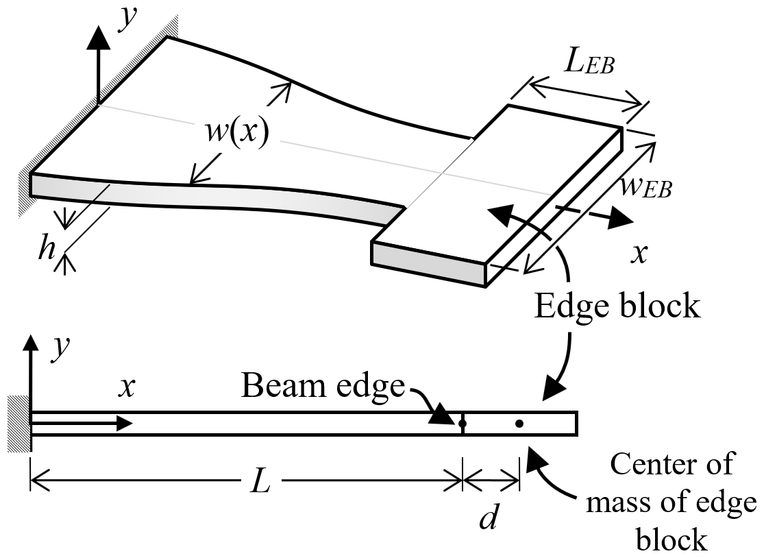
Figure 1Schematic description of a PVEH device, which is patterned only in the device layer. The PVEH is constructed from a cantilever and an edge block. The cantilever has a length L, a uniform thickness h and a rectangular cross section with a width w(x) which changes along the x axis. The edge block has a length LEB and a width wEB, and it is connected at x=L.
It is assumed that the Euler–Bernoulli beam theory is applicable, where the governing equation that determines the out-of-plane displacement y(t,x) in free vibrations, and is given by
Here, ρ is the density of the elastic material and E is the Young modulus. The term is the effective bending rigidity of the beam cross section, where is given by
We assume that the vibrations of the cantilever can be described as the product of a time-periodic function T(t) and a deflection mode Y(x):
The amplitude of the axial strain at the top surface of the beam is therefore given by
The aim here is to determine the functional form of w(x) such that the strain on the top surface is uniform (). Substituting this into Eq. (4) yields
From Eq. (5), we can deduce that the curvature along the beam must be uniform. It follows that
where the boundary conditions Y(0) = 0 and Y'(0) = 0 have been imposed.
Substituting Eqs. (3) and (6) into Eq. (1) yields
which may be rearranged in the form
It follows that the time harmonic solution must satisfy
and without loss of generality, we may consider the solution
Accordingly, the cantilever width w(x) must satisfy the following differential equation:
Due to the edge block accelerations, a resultant transverse force and a resultant moment are applied at the beam's far edge, as illustrated in Fig. 2.
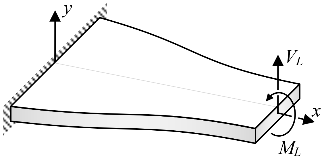
Figure 2The loads applied by the device-layer edge block on the far edge of the cantilever beam.
From Eq. (6), it follows that at the far edge of the beam, the transverse and angular accelerations of the edge block are given by
The resultant force and moment at the far edge x=L that are applied by the edge block and induced due to the edge block transverse and angular accelerations are given by
At the far edge, the resultant shear force and the resultant bending moment are given by
After substituting Eqs. (12) and (13) into Eq. (14) and comparing to Eq. (16), it follows that
Substituting Eqs. (12) and (13) into Eq. (15) and comparing to Eq. (17) yields
Now, Eq. (11) can be solved analytically from x=L back to x= 0 beginning with the two edge conditions for w(x) given by Eqs. (18) and (19). The analytic result of this is given by
Here, I0.25 and K0.25 are modified Bessel functions, and the constants a1 and a2 are determined from the boundary conditions (18) and (19).
We consider a typical cantilever PVEH with a device-layer edge block. The edge block has a width of wEB= 200 µm and various lengths, LEB= 100, 200, 300 and 400 µm. We target a vibrations frequency ω= 30 000 rad s−1 (i.e., f= 4.774 kHz), the cantilever length is L= 2000 µm, and the width w(x) varies along the beam. The considered PVEH devices are patterned only in the device layer, which has a uniform thickness h= 10 µm. For mechanical properties, we consider devices that are made using SOI wafer technology from single-crystalline silicon (SCS) in the (110) orientation, where the density is ρ= 2330 kg m−3 and the material moduli are Exx= 169.7 GPa, Gxy= 80 GPa and νxz= 0.0606. For each of the edge block lengths LEB, the constants a1 and a2 were computed by applying the boundary conditions in Eqs. (18)–(19), using MATLAB (R2023a). These constants were substituted into Eq. (20) to compute the beam width w(x). An example of an optimal Bessel tapered planform is presented in Fig. 3.
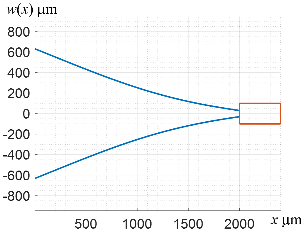
Figure 3The optimal Bessel tapered planform for an edge block length of LEB= 400 µm. The blue lines mark the beam width w(x), and the orange lines mark the edge block.
To validate our model, we simulate the eigenfrequency for each PVEH using COMSOL™ 6.0 finite-element code (COMSOL, 2022). Each simulation includes a Bessel tapered planform with a matching device-layer edge block. Figure 4 presents a typical geometry and mesh. In the simulations, we used quadratic serendipity quadrilateral elements, with a restriction on each element size (i.e., minimum and maximum length). It was verified that the simulation results converge with mesh refinement.
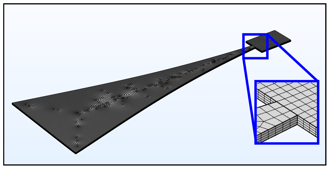
Figure 4A typical geometry and mesh used in the finite-element simulations. The zoomed-in view focuses on the connection of the edge block to the beam.
The aim of our work is to optimize the planform of the PVEH such that the strain distribution over the top surface of the cantilever is uniform. To this end, we define the measure of nonuniformity of the axial strain over the top surface of the cantilever εxx by
The measure of nonuniformity in Eq. (21) is identically zero (i.e., 0) only when the axial strain over the top surface of the cantilever εxx is uniform (i.e., εxx is not dependent on x or z).
For each length of edge block LEB, Table 1 presents the width of the beam at the clamped edge w(0) and the far edge w(L), the simulated eigenfrequency ωn and the simulated nonuniformity of axial strain .
Table 1The optimal parameters for different device-layer edge blocks and the simulated axial strain nonuniformity.
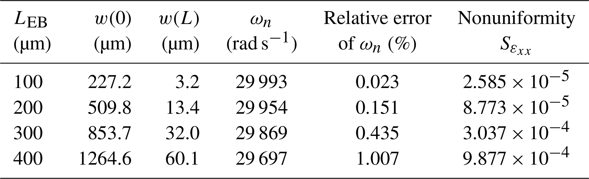
The values of the simulated frequency ωn in Table 1 validate our model, which considered the target frequency of ω= 30 000 rad s−1. The relative errors in ωn suggest that there is a discrepancy between the analysis and the simulations. Our analysis considers the Euler–Bernoulli beam theory, which neglects shear deformations that are not neglected in the finite-element simulations, resulting in a discrepancy of 1 %.
The low values of the nonuniformity in Table 1 suggest that the strain is indeed rather uniform. To examine the scale of these low-value nonuniformities, we compare the optimal Bessel tapered planforms to non-optimal planforms. As a test case, we consider the third entry in Table 1, with LEB= 300 µm.
Figure 5 shows the strain distribution over the top surface of the optimal Bessel tapered beam for the third entry in Table 1. For this optimal Bessel tapered beam, the related nonuniformity is 3.037 × 10⁻⁴, and it is clear from Fig. 5 that the strain over the top surface is rather uniform.
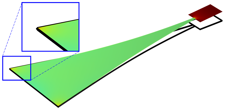
Figure 5The axial strain distribution of the optimal Bessel tapered planform for edge block length LEB= 300 µm. The uniform color suggests that the strain is rather uniform. The reddish corners at the clamped edge suggest that some strain concentration occurs at these corners (zoomed in). The color scale is between red (maximal strain) and blue (minimal strain) with green at the average of maximal and minimal strains.
For comparison, we consider a non-optimal cantilever beam for the same edge block, in which the Bessel edges are replaced with straight lines. This beam consists of the same widths at the clamped and the far edge (i.e., same w(0) and w(L)), but this is a width that is linearly tapered.
Figure 6 shows the axial strain distribution over the top surface of the trapezoidal beam. For this non-optimal trapezoidal beam, the nonuniformity is 1.643 × 10⁻², which is 50 times larger than the value obtained for the optimal planform.
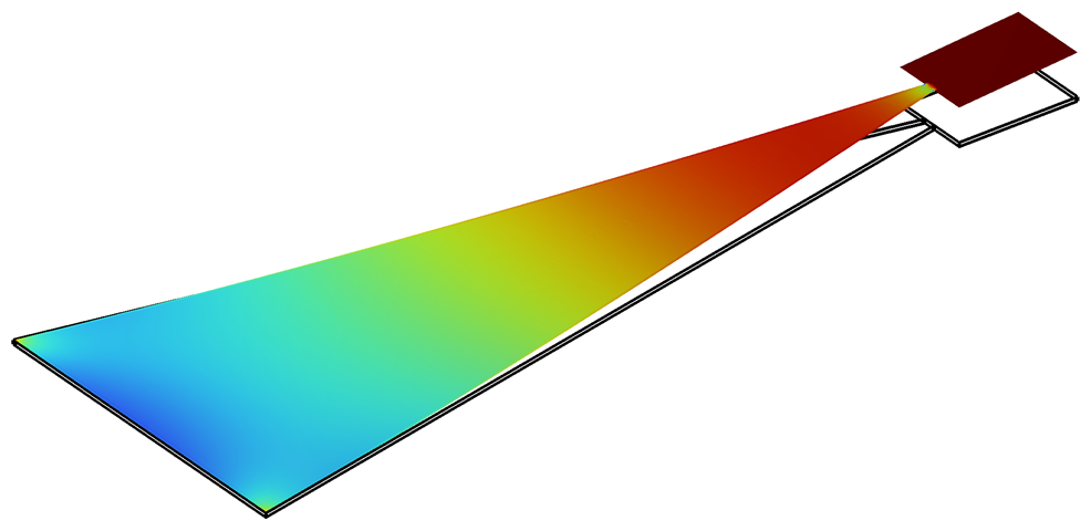
Figure 6The axial strain distribution of a non-optimal trapezoidal planform for edge block length LEB= 300 µm. The color scale is between red (maximal strain) and blue (minimal strain) with green at the average of maximal and minimal strains.
For the other cases of LEB= 100, 200 and 400 µm, the strains of the Bessel tapered planforms were more uniform relative to the related trapezoidal planforms by a factor of ∼ 580, ∼ 175 and ∼ 18, respectively.
To simplify our model, we assume that the device-layer edge block responds like a rigid body. This facilitates the calculation of the resultant shear force and resultant moment at the edge cross section, where the edge block is connected to the cantilever. If, however, the edge block length and width are significantly large such that deformation of the edge block is substantial, then deriving the relevant resultant shear force and resultant moment may require more rigorous analysis.
For the sufficiently small edge blocks considered in the present study, our simulations confirm that the edge block deformation is marginal, and therefore the beam planform predicted by our model results in very small simulated strain nonuniformities in the piezoelectric layer.
In any case, the strain nonuniformities predicted by our model are small, and the difference between a trapezoidal planform and a Bessel function planform may not be large. However, in previous studies it was identified, through simulations, that in some cases with a nondominant edge block, the performance of a PVEH with curved contours is superior (Ben Ayed et al., 2014; Dietl and Garcia, 2010; Park et al., 2012; Salmani et al., 2015). The present study provides an analysis that explains why curved contours may be superior, and provides a model with predictive capabilities.
This study presents a derivation of the optimal planform of a PVEH with a device-layer edge block. It is shown that the optimal planform of such a device is defined by Bessel functions. Using our model, it is possible to design a PVEH with an optimal performance such that the amplitude of the strain in the piezoelectric layer is uniform. Finite-element simulations show good agreement with the analytic derivation, validating the presented model.
The relevance of this model is that it provides a tool with predictive capabilities for designing PVEH devices with optimal performance.
No data sets were used in this article.
ES contributed to the study conceptualization, formal analysis, investigation, methodology, validation, visualization and writing. SL contributed to the study conceptualization, formal analysis and investigation. DE contributed to conceptualization, funding acquisition, methodology, supervision and writing.
The contact author has declared that none of the authors has any competing interests.
Publisher’s note: Copernicus Publications remains neutral with regard to jurisdictional claims made in the text, published maps, institutional affiliations, or any other geographical representation in this paper. While Copernicus Publications makes every effort to include appropriate place names, the final responsibility lies with the authors.
This article is part of the special issue “Eurosensors 2024”. It is a result of the EUROSENSORS XXXVI, Debrecen, Hungary, 1–4 September 2024.
This research has been supported by the Israel Science Foundation (grant no. 1820/22).
This paper was edited by Gabor Battistig and reviewed by two anonymous referees.
Ben Ayed, S., Najar, F., and Abdelkefi, A.: Shape improvement for piezoelectric energy harvesting applications, in: 3rd International Conference on Signals, Circuits and Systems, SCS 2009, 1–6, https://doi.org/10.1109/ICSCS.2009.5412553, 2009.
Ben Ayed, S., Abdelkefi, A., Najar, F., and Hajj, M. R.: Design and performance of variable-shaped piezoelectric energy harvesters, J. Intel. Mat. Syst. Str., 25, 174–186, https://doi.org/10.1177/1045389X13489365, 2014.
Baker, J., Roundy, S., and Wright, P.: Alternative geometries for increasing power density in vibration energy scavenging for wireless sensor networks, in: 3rd International Energy Conversion Engineering Conference, 15–18 August 2005, San Francisco, California, USA, 959–970, https://doi.org/10.2514/6.2005-5617, 2005.
Benasciutti, D., Moro, L., Zelenika, S., and Brusa, E.: Vibration energy scavenging via piezoelectric bimorphs of optimized shapes, Microsyst. Technol., 16, 657–668, https://doi.org/10.1007/s00542-009-1000-5, 2010.
Chen, Z. S., Yang, Y. M., and Deng, G. Q.: Analytical and experimental study on vibration energy harvesting behaviors of piezoelectric cantilevers with different geometries, in: 1st International Conference on Sustainable Power Generation and Supply, 6–7 April 2009, Nanjing, China, 1–6, https://doi.org/10.1109/SUPERGEN.2009.5348290, 2009.
COMSOL: Multiphysics® v.6.0, COMSOL AB, Stockholm, Sweden, http://www.comsol.com (last access: 4 July 2024), 2022.
Cowen, A., Hames, G., Glukh, K., and Hardy, B.: PiezoMUMPs Design Handbook, MEMSCAP Inc., http://www.memscap.com/products/mumps/piezomumps (last access: 14 February 2021), 2014.
Dietl, J. M. and Garcia, E.: Beam shape optimization for power harvesting, J. Intel. Mat. Syst. Str., 21, 633–646, https://doi.org/10.1177/1045389X10365094, 2010.
Du, S., Jia, Y., Chen, S.-T., Zhao, C., Sun, B., Arroyo, E., and Seshia, A. A.: A new electrode design method in piezoelectric vibration energy harvesters to maximize output power, Sensors Actuators A Phys., 263, 693–701, 2017.
Gallina, M. and Benasciutti, D.: Finite element analysis of optimized piezoelectric bimorphs for vibrational “energy harvesting,” in: International CAE Conference 2013, 21–22 October 2013, Pacengo del Garda, Verona, Italy, 1–4, https://www.researchgate.net/profile/Denis-Benasciutti/publication/257929811_Finite_element_analysis_of (last access: 1 July 2024), 2013.
Goldschmidtboeing, F. and Woias, P.: Characterization of different beam shapes for piezoelectric energy harvesting, J. Micromech. Microeng., 18, 104013, https://doi.org/10.1088/0960-1317/18/10/104013, 2008.
Halvorsen, E. and Dong, T.: Analysis of tapered beam piezoelectric energy harvesters, in: PowerMEMS 2008+ microEM, 241–244, https://citeseerx.ist.psu.edu/document?repid=rep1&type=pdf&doi=92d13524f79e585a7c73067a858c0f200347463f (last access: 14 April 2024), 2008.
Hosseini, R. and Hamedi, M.: An investigation into resonant frequency of trapezoidal V-shaped cantilever piezoelectric energy harvester, Microsyst. Technol., 22, 1127–1134, https://doi.org/10.1007/s00542-015-2583-7, 2016.
Jia, Y. and Seshia, A. A.: Five topologies of cantilever-based MEMS piezoelectric vibration energy harvesters: a numerical and experimental comparison, Microsyst. Technol., 22, 2841–2852, https://doi.org/10.1007/s00542-015-2599-z, 2016.
Lee, S., Youn, B. D., and Jung, B. C.: Robust segment-type energy harvester and its application to a wireless sensor, Smart Mater. Struct., 18, 095021, https://doi.org/10.1088/0964-1726/18/9/095021, 2009.
Mateu, L. and Moll, F.: Optimum piezoelectric bending beam structures for energy harvesting using shoe inserts, J. Intel. Mat. Syst. Str., 16, 835–845, https://doi.org/10.1177/1045389X05055280, 2005.
Matova, S. P., Renaud, M., Jambunathan, M., Goedbloed, M., and Van Schaijk, R.: Effect of length/width ratio of tapered beams on the performance of piezoelectric energy harvesters, Smart Mater. Struct., 22, 075015, https://doi.org/10.1088/0964-1726/22/7/075015, 2013.
Miller, L. M., Emley, N. C., Shafer, P., and Wright, P. K.: Strain enhancement within cantilevered, piezoelectric MEMS vibrational energy scavenging devices, Adv. Sci. Technol., 54, 405–410, https://doi.org/10.4028/www.scientific.net/AST.54.405, 2008.
Miller, L. M., Halvorsen, E., Dong, T., and Wright, P. K.: Modeling and experimental verification of low-frequency MEMS energy harvesting from ambient vibrations, J. Micromech. Microeng., 21, 045029, https://doi.org/10.1088/0960-1317/21/4/045029, 2011.
Muthalif, A. G. A. and Nordin, N. H. D.: Optimal piezoelectric beam shape for single and broadband vibration energy harvesting: Modeling, simulation and experimental results, Mech. Syst. Signal Pr., 54, 417–426, https://doi.org/10.1016/j.ymssp.2014.07.014, 2015.
Park, J., Lee, S., and Kwak, B. M.: Design optimization of piezoelectric energy harvester subject to tip excitation, J. Mech. Sci. Technol., 26, 137–143, https://doi.org/10.1007/s12206-011-0910-1, 2012.
Pillai, G., Zope, A. A., and Li, S.: Piezoelectric-Based Support Transducer Design to Enable High-Performance Bulk Mode Resonators, J. Microelectromech. S., 28, 4–13, https://doi.org/10.1109/JMEMS.2018.2877784, 2019.
Raju, S. S., Umapathy, M., and Uma, G.: High-output piezoelectric energy harvester using tapered beam with cavity, J. Intel. Mat. Syst. Str., 29, 800–815, https://doi.org/10.1177/1045389X17721044, 2018.
Rosa, M. and De Marqui Junior, C.: Modeling and analysis of a piezoelectric energy harvester with varying cross-sectional area, Shock Vib., 2014, 930503, https://doi.org/10.1155/2014/930503, 2014.
Roundy, S., Leland, E. S., Baker, J., Carleton, E., Reilly, E., Lai, E., Otis, B., Rabaey, J. M., Wright, P. K., and Sundararajan, V.: Improving power output for vibration-based energy scavengers, IEEE Pervas. Comput., 4, 28–36, https://doi.org/10.1109/MPRV.2005.14, 2005.
Salman, E., Lustig, S., and Elata, D.: On the optimal planform of a cantilever unimorph piezoelectric vibrating energy harvester, Smart Mater. Struct., 33, 35029, https://doi.org/10.1088/1361-665X/ad28d0, 2024a.
Salman, E., Rosenstock, D., and Elata, D.: The optimal axial strain distribution in a piezoelectric vibrating energy harvester (PVEH), in: EUROSENSORS 2024, 247–248, https://doi.org/10.5162/EUROSENSORSXXXVI/PT1.270, 2024b.
Salman, E., Rosenstock, D., and Elata, D.: The optimal distribution of axial strain amplitude in a piezoelectric vibrating energy harvester, J. Sens. Sens. Syst., 14, 147–152, https://doi.org/10.5194/jsss-14-147-2025, 2025.
Salmani, H., Rahimi, G. H., and Hosseini Kordkheili, S. A.: An Exact Analytical Solution to Exponentially Tapered Piezoelectric Energy Harvester, Shock Vib., 2015, 426876, https://doi.org/10.1155/2015/426876, 2015.
Yang, K., Li, Z., Ling, Y., Chen, D., and Ye, T.: Research on the resonant frequency formula of V-shaped cantilevers, in: 4th IEEE International Conference on Nano/Micro Engineered and Molecular Systems, NEMS 2009, 5–8 January 2009, Shenzhen, China, 59–62, https://doi.org/10.1109/NEMS.2009.5068527, 2009.
Zhang, G., Gao, S., Liu, H., and Niu, S.: A low frequency piezoelectric energy harvester with trapezoidal cantilever beam: theory and experiment, Microsyst. Technol., 23, 3457–3466, https://doi.org/10.1007/s00542-016-3224-5, 2017.