the Creative Commons Attribution 4.0 License.
the Creative Commons Attribution 4.0 License.
 | 28 Oct 2025
Silicon-based strain gauge sensors embedded in composite structures for real-time strain and creep analysis
Gaëtan Herry
William Caroba
Maxime Harnois
France Le Bihan
This study demonstrates how integrating silicon mechanical sensors into composite structures enables the detection of internal structural variations and can find applications in process monitoring or structural health monitoring (SHM). It introduces a novel, minimally intrusive process for embedding sensors within composites (substrate-free transfer-printed sensor). Both temperature and strain effects are studied and presented. The silicon strain sensor exhibits high sensitivity due to the piezoresistive effect. The combination of high temperature and strain produces a plastic degradation of the material, linked to the creep phenomenon of the composite's epoxy resin binder. This internal structure modification in the composite is directly detected with the strain gauges in real time.
- Article
(1529 KB) - Full-text XML
- BibTeX
- EndNote


Composite materials are increasingly being used across a wide range of applications (Harussani, 2022; Ravishankar et al., 2019; The Composite Sky, 2024), and composite industry is of high interest for key sectors such as the aerospace, automotive, and construction industries. Optimizing composite manufacturing processes and monitoring their structural state are key issues for ensuring safety, environmental sustainability, and cost-effectiveness (Thori et al., 2013; Ahmed et al., 2023). They are at the core of the SHM (structural health monitoring) focus. Such innovations may aim to optimize processing parameters, develop new materials with enhanced properties, or design smart composites. For this last goal, many functions can be integrated into composites structures as heaters, antennas, or several types of strain sensors (Sensexpert, 2023; Kuang et al., 2001; Yao et al., 2011). Some solutions exist for introducing strain sensors into composites (Sousa et al., 2020; Wang et al., 2022; Zhao et al., 2012), such as optical fibers, but they remain complex to implement and are intrusive. We propose an alternative solution with electronic devices, especially resistive gauges sensors. These devices are well known. They can be achieved with metallic thin layers, with a low gauge factor (a few units) but a large range of detection (up to 5 % of deformation) (Zhang and Hoshino, 2019). Semiconducting materials such as silicon are interesting because, due to the piezoresistive effect, they have a large gauge factor (20 to 100, depending on their structures and doping levels) but a limited deformation range (1 % maximum) (French and Evans, 1989). However, the main goal is to introduce some gauge factor with a minimal perturbation of the composite materials. The first idea is to decrease the thickness of the substrate to decrease the effect of a foreign body in the test medium. But, in this case, the substrate always has an impact on mechanical properties. In order to reduce it as much as possible, we develop a new process that allows us to insert a gauge factor into the core of a composite without any substrate. Our low-intrusion strain gauge instrumentation method offers physical and structural insights from within the composite structure itself. Indeed, it can maintain the composite's structural integrity by embedding the sensor substrate-free at its core. Remarkably, even with its thickness and intrusiveness minimized, it retains the high-sensitivity characteristic of the silicon sensors.
2.1 Overall process
The process involves manufacturing microcrystalline silicon strain gauges and transferring them, substrate-free, into one of the plies of the composite material, made from a combination of fiber glass and epoxy resin. It is worth noting that transfer-printing technology has already been proven to be effective for integrating electronic functions into textiles (Rogel et al., 2016). Figure 1 shows the result of a ply including silicon strain gauges and the resulting composite material made of several plies and including four silicon strain gauges linked to external electrical contacts.
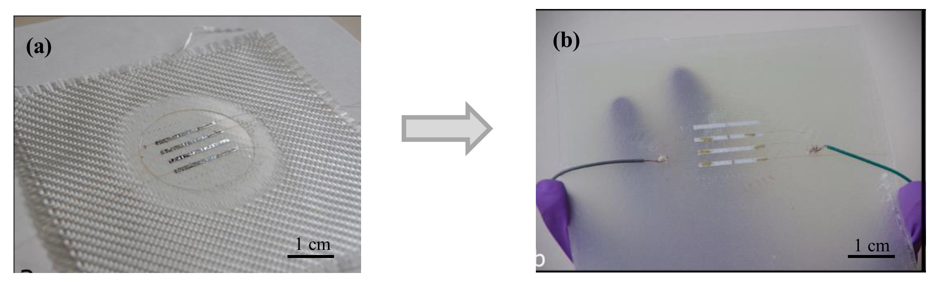
Figure 1Composite with silicon gauges. (a) Gauges transferred on a ply. (b) Final structure of the instrumented composite.
2.2 Strain gauge process
Strain gauges are fabricated on a temporary substrate (silicon wafer in Fig. 2). A double-layer (PMMA – polymethyl methacrylate; PI – durimide, optimized with thicknesses of 1 µm each) is used to ensure a reliable final lift-off of the device and a protection during the process steps. The doped silicon layer, 90 nm thick, is obtained from the PECVD (plasma enhanced chemical vapor deposition) step. It is a randomly oriented polycrystalline silicon (μC-Si) with a thickness of 90 nm. It is then plasma etched by using RIE (reactive-ion etching) and SF6 gas (Herry et al., 2024). Different sizes can be obtained from micrometric to millimetric ranges. A 150 nm thick aluminum (Al) layer is deposited with the Joule effect and used for electrical contacts.
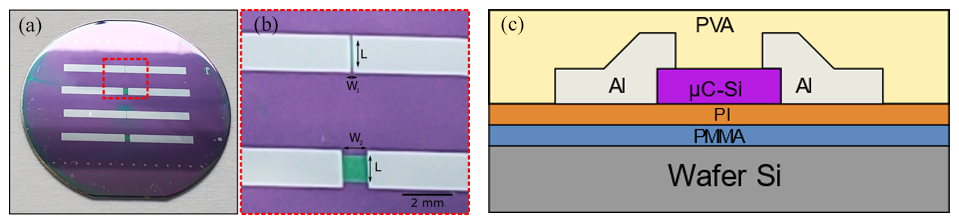
Figure 2Silicon gauges processed on silicon wafer: (a) four sensors achieved on silicon wafer, (b) geometries W and L (L = 1400 µm, W1=100 µm and W2=1200 µm), (c) scheme of the different layers before the transfer.
2.3 Composite structure
The composite is fabricated with several fiber glass layers (see Fig. 3) as reinforcement and epoxy as a matrix. The sensor whose structure is shown in Fig. 2c is transferred onto a ply (see Fig. 3a). It is then covered with a PI layer that is plasma etched (O2 plasma) after the transfer step. Then, only aluminum and silicon layers remain on the composite ply. The final fabrication of the multilayer composite then consists of the superposition of several plies, as mentioned in Fig. 3b. The manufacturing involves vacuum infusion of epoxy on fiber glass layers using a mold. Each ply has a thickness of around 250 µm. The connection wires are obtained by metallic wires previously inserted into the fiber matrix and then bounded with silver ink or are positioned at the side of the composite ply and linked to electrical wires. The final structure is shown in Fig. 1b.
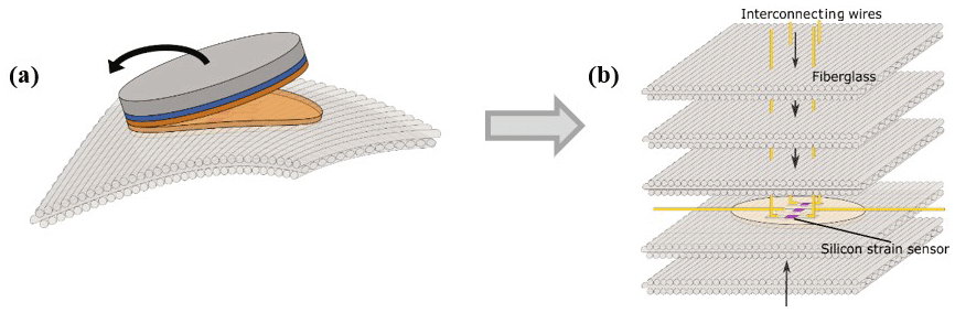
Figure 3(a) Illustration of the lift-off silicon gauge. (b) Structure of the multilayer composite.
3.1 Sensitivity to strain
The sensitivity of such a device is determined by the gauge factor, linked to the resistance variation with the strain εI following Eq. (1):
The strain is calculated with different radii of curvature as explained in Fig. 4a. The initial value R0 of the resistance is measured in flat conditions. Several radii (r in Fig. 4b) allow us to apply different strain values. In each case, the relative strain is calculated by using the equation shown in Fig. 4a. In our case, the composite is made of five fiber glass layers for a total thickness of 1.2 mm. The distance between the neutral plan (in the middle of the thickness, where the applied stress is null) and the sensor layer is assumed, from the geometrical fabrication structure, to be equal to 130 µm. The relative resistance variation is then reported versus the relative strain ε.
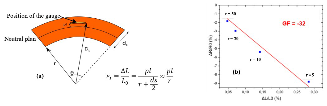
Figure 4Determination of the gauge factor: (a) calculation of the strain depending on the sensor position inside the composite, with pl being the distance between the neutral plan and the sensor and ds being the thickness of the composite. (b) Relative variation of the resistance for different strain values ε and determination of the gauge factor from the slope of the curve.
The gauge factor is then estimated from the slope of the relative change in resistance versus the relative strain. One example is given in Fig. 4b. It shows that, as the silicon is an N type, the resistance decreases with the strain, leading to a negative value of the gauge factor. This value, equal to −32, is significantly higher than the gauge factor obtained with classical metallic gauges (gauge factor, GF, of around 2). This is due to the piezoresistive effect involved in the silicon structure (Herry et al., 2024; Garcia Castro et al., 2020). The silicon gauges show no electrical degradation that could have occurred during the transfer process. Moreover, the gauge factor is the same as the one obtained with similar gauges manufactured directly on thin flexible films of a Kapton (polyimide film) structure (Herry et al., 2024; Garcia Castro et al., 2020).
3.2 Sensitivity to temperature
As is typical for semiconducting materials, the resistance decreases as the temperature increases. This is shown in Fig. 5a for several temperature steps ranging from 20 to 80 °C. The sensitivity to temperature, defined in Eq. (2), with T0=20 °C and R0=R(T0), shows that the change in resistance is linear in relation to temperature. Furthermore, the stability decreases at high temperatures, above 70 °C.
3.3 Combination of strain and temperature: creep detection
We first focus on the behavior of the composite and the response of strain gauges below 60 °C. During these measurements, several temperature steps are operated versus time. This allows us to measure the variation in the resistance when the temperature is increased, as well as its stabilization for each temperature level. Figure 5b shows, with a red line, the temperature steps from 20 to 60 °C. The variation in the resistance is measured in flat conditions (black line in Fig. 5b). It shows that, as the temperature increases, the resistance decreases. The resistance remains constant when the temperature is stabilized. This is the usual behavior for semiconducting material. When a constant strain is applied, as shown in Fig. 5b (blue line), the resistance is lower than in flat conditions. This is observed for each temperature step. Moreover, we can also observe that, as the curves for flat or stained devices are parallel, the gauge factor is not sensitive to the temperature and remains constant.
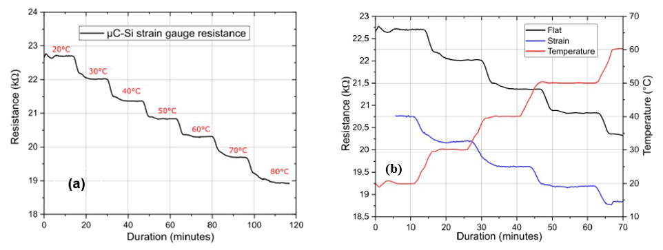
Figure 5Effect of temperature: (a) from 20 to 80 °C, with a decrease in the resistance, and (b) from 20 to 60 °C for flat or strained devices, showing the gauge factor stability.
It has been observed previously that the resistance, under flat conditions, is less stable at high temperatures, especially at the 70 and 80 °C steps, as shown in Fig. 5a. This is due to the plastic deformation of the composite, which starts to appear at a temperature above 60 °C. Figure 6 shows the comparison of resistance versus temperature under flat or strained conditions from 20 to 80 °C. It is clearly shown that, above 60 °C, the resistance of the sensor increases strongly. This behavior is linked to a plastic deformation of the internal structure of the composite. Indeed, we can observe that the shape of the composite piece changed after the cooling of the structure in this case (it stays curved). This demonstrates that the structure of the composite has changed, and so the internal strain sensor is able to detect a plastic deformation in real time, induced, in our case, by the temperature increase. It has also been shown that this deformation is linked to the transition temperature of the epoxy, leading to a slippage of the internal layers of the composite.
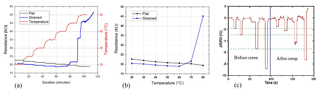
Figure 6Effect of temperature and detection of creep above 60 °C: (a) comparison of changes with temperature for flat or strained samples, (b) variation in the mean resistance with both conditions, (c) strain measurements before and after degradation.
A treatment at 80 °C on flat conditions allows us to recover the flat shape of the composite. As shown in Fig. 6c, the composite is tested again under several strain values to compare its behavior before and after the creep. This figure shows that, after this recovery, the strain gauge continues to work and is able to detect strain inside the composite. However, the sensitivities before and after creep are not the same, as proven by the decrease in the resistance variation for the same strain value. So, considering the intensity of the degradation, the injury can lead to a decrease in the sensitivity of the strain gauges, as observable in Fig. 6c.
We have demonstrated successful integration of silicon strain gauges into the core of composite materials without damaging the devices. These low-intrusion methods enable us to obtain sensors capable of both measuring internal temperatures and detecting structural deformations. Furthermore, they provide valuable insights into significant internal structural changes, such as binder creep and plastic deformation, which are crucial for understanding the behavior of composite materials.
No specific software code was developed for this research.
The research data were collected in laboratory books; thus, they are stored in written form and are not available on the internet. Data can be made available from the corresponding author upon request.
GH developed the sensor technology and its insertion into composite materials under the supervision of MH, who was behind the development of the technology transfer process at the heart of the materials. Deformation characterization was also carried out by GH and WC under the supervision of FLB, who carried out the combined temperature and deformation characterizations and formatted the results. MH and FLB supervised the overall project.
The contact author has declared that none of the authors has any competing interests.
Publisher's note: Copernicus Publications remains neutral with regard to jurisdictional claims made in the text, published maps, institutional affiliations, or any other geographical representation in this paper. While Copernicus Publications makes every effort to include appropriate place names, the final responsibility lies with the authors. Views expressed in the text are those of the authors and do not necessarily reflect the views of the publisher.
This article is part of the special issue “Eurosensors 2024”. It is a result of the EUROSENSORS XXXVI, Debrecen, Hungary, 1–4 September 2024.
The authors thank the NanoRennes platform belonging to RENATECH+ (French National Network of Facilities for Micro nanotechnology). This publication is supported by the European Union through the European Regional Development Fund (ERDF) and by the Ministry of Higher Education and Research, Brittany and Rennes Metropole, through the CPER project SOPHIE/STIC & Ondes.
This paper was edited by Péter Fürjes and reviewed by three anonymous referees.
Ahmed, S., Bodaghi, M., Nauman, S., and Muhammad Khan, Z.: Additive Manufacturing of Flexible Strain Sensors Based on Smart Composites for Structural Health Monitoring with High Accuracy and Fidelity, Advanced Engineering Materials, 25, 2300763, https://doi.org/10.1002/adem.202300763, 2023.
French, P. J. and Evans, A. G. R.: Piezoresistance in polysilicon and its applications to strain gauges, Solid-State Electronics, 32, 1–10, https://doi.org/10.1016/0038-1101(89)90041-5, 1989.
Garcia Castro, F., de Sagazan, O., Coulon, N., Simon, C., and Le Bihan, F.: ICP-CVD μ-Si Layers Optimization for Strain Gauges on Flexible Substrates, Sensors and Actuators A: Physical, 315, 112261, https://doi.org/10.1016/j.sna.2020.112261, 2020.
Harussani, M. M.: Recent applications of carbon-based composites in defence industry: A review, Defence Technology, 18, 1281–1300, https://doi.org/10.1016/j.dt.2022.03.006, 2022.
Herry, G., Fustec, J.-C., Le Bihan, F., and Harnois, M.: Substrate-Free Transfer of Silicon- and Metallic-Based Strain Sensors on Textile and in Composite Material for Structural Health Monitoring, ACS Appl. Mater. Interfaces, 16, 22113–22121, https://doi.org/10.1021/acsami.4c01055, 2024.
Kuang, K. S. C., Kenny, R., Whelan, M. P., Cantwell, W. J., and Chalker, P. R.: Embedded fibre Bragg grating sensors in advanced composite materials, Composites Science and Technology, 61, 1379–1387, https://doi.org/10.1016/S0266-3538(01)00037-9, 2001.
Ravishankar, B., Nayak, S. K., and Kader, M. A.: Hybrid composites for automotive applications – A review, Journal of Reinforced Plastics and Composites, 38, 835–845, https://doi.org/10.1177/0731684419849708, 2019
Rogel, R., Le Borgne, B., Mohammed-Brahim, T., Jacques, E., and Harnois, M.: Spontaneous Buckling of Multiaxially Flexible and Stretchable Interconnects Using PDMS/Fibrous Composite Substrates, Advanced Materials Interfaces, 4, https://doi.org/10.1002/admi.201600946, 2016.
Sensexpert: Reach for the Sky: How to Optimize Aerospace Composite Manufacturing, https://www.sensxpert.com/blog/reach-sky-aerospace-composite-manufacturing/ (last access: April 2024), 2023.
Sousa, J., Marques, J., Garcia, M., Infante, V., and Amaral, P.: Mechanical characterization of sandwich composites with embedded sensors, Engineering Failure Analysis, 117, 104765, https://doi.org/10.1016/j.engfailanal.2020.104765, 2020.
The Composite Sky: Advanced Materials Defining Modern Aerospace, https://www.addcomposites.com/post/the-composite-sky-advanced-materials-defining-modern-aerospace, last access: 25 October 2024.
Thori, P., Sharma, P., and Bhargava, M.: An Approach of Composite Materials in Industrial Machinery: Advantages, disadvantages and Applications, IJRET, 2, 350–355, 2013.
Wang, Y., Hu, S., Xiong, T., Huang, Y., and Qiu, L.: Recent progress in aircraft smart skin for structural health monitoring, Structural Health Monitoring, 21, 2453–2480, https://doi.org/10.1177/14759217211056831, 2022.
Yao, L., Jiang, M., Zhou, D., Xu, F., Zhao, D., Zhang, W., Zhou, N., Jiang, Q., and Qiu, Y.: Fabrication and characterization of microstrip array antennas integrated in the three dimensional orthogonal woven composite, Composites Part B: Engineering, 42, 885–890, https://doi.org/10.1016/j.compositesb.2011.01.006, 2011.
Zhang, J. X. J. and Hoshino, K., Chapter 6 – Mechanical transducers: Cantilevers, acoustic wave sensors, and thermal sensors, in: Molecular Sensors and Nanodevices (Second Edition), , edited by: John X.J. Zhang, Kazunori Hoshino, In Micro and Nano Technologies, Academic Press, 311-412, https://doi.org/10.1016/B978-0-12-814862-4.00006-5, 2019.
Zhao, D., Liu, T., Zhang, M., Liang, R., and Wang, B.: Fabrication and characterization of aerosol-jet printed strain sensors for multifunctional composite structures, Smart Mater. Struct., 115008, https://doi.org/10.1088/0964-1726/21/11/115008, 2012.