the Creative Commons Attribution 4.0 License.
the Creative Commons Attribution 4.0 License.
 | 27 Mar 2025
Cost-oriented sensor concept for magnetostrictive force measurement and its material requirements
Alexander Hofmann
Marc Heusinger
A cost-oriented sensor concept based on the conversion principle of inverse magnetostriction is presented. The main element of the concept is a disc-shaped sensor enclosing a remanent magnetization, which will give rise to an externally measurable magnetic field changing under a load. The magnetic properties of a commonly used cold working steel as one potential sensor material under soft-annealed and hardened conditions are analysed and discussed regarding their impact on sensor performance.
- Article
(2735 KB) - Full-text XML
- BibTeX
- EndNote


The presented force sensor concept based on the inverse magnetostrictive measuring principle intends to provide a force sensor at a lower cost compared to established sensor concepts. It furthermore focuses on easy integration into an application, involving high stiffness and a low packaging height. In contrast, increased accuracy compared to state-of-the-art sensors is not in the scope of the concept. The essence of this concept is presented in Hofmann and Heusinger (2024), where pre-load measurement at bearing arrangements is named as one potential application for the sensor concept. As the sensor performance greatly depends on the magnetic properties of the materials used, special attention needs to be paid to these properties.
2.1 Physical principle
Magnetostriction generally determines a mutual dependence of magnetic and mechanical material properties. The change in length of a ferromagnetic rod under magnetization is known as the Joule effect (Joule, 1842) and enables the implementation of actuator concepts, whereas its inversion, called the Villari effect (Villari, 1865), forms the basis for sensors (Tumanski, 2011). According to the Villari effect, the foremost permeability and remanent flux density of a ferromagnetic body change when being subjected to mechanical stress (Ewing, 1892). As measuring these quantities enables the determination of the loads acting on a body, such a body is generally referred to as a primary sensor.
2.2 Known embodiments
Known force sensors using the inverse magnetostrictive principle with permeability measurement are explained in Schiessle (2016) and Kleinke and Uras (1994). A commonly known embodiment is based on two coils that are wound on a magnetostrictive primary sensor with their coil axes perpendicularly aligned with each other. One coil is powered by a sinusoidal current, causing a magnetic AC field. In the unloaded state of such an arrangement, this magnetic field does not induce voltage in the secondary coil due to its orientation perpendicular to the exciting coil and the quasi-isotropic behaviour of the primary sensor's permeability. Once the primary sensor is mechanically loaded, the AC field's direction deviates from the exciting coil's axis due to the anisotropic permeability changes caused by the Villari effect, inducing a voltage in the secondary coil that can be used to characterize the acting load (Schiessle, 2016).
Such a sensor concept is known to be robust and simple but limited in accuracy (Schiessle, 2016). Still, the requirement of components driving the excitation coil and reading out the secondary coil involves costs that limit the application range.
2.3 Principle of operation of the present sensor concept
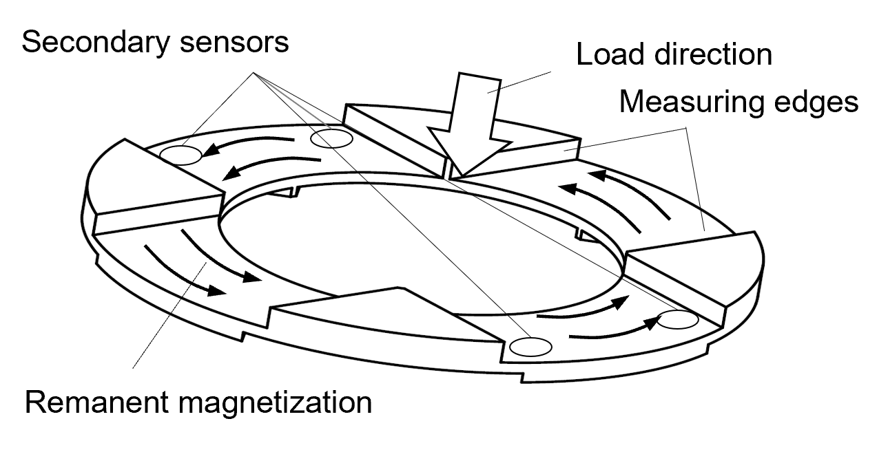
The present sensor concept avoids the usage of such costly components by measuring remanent magnetization instead of actively driving a magnetic field. As magnetic flux density is stronger at flux lines forming closed loops inside a highly permeable material (Tumanski, 2011), the primary sensor's shape should allow the formation of such loops. Figure 1 shows the disc-like shape of the primary sensor employed in the present concept enabling this.
Sensing the change in a primary sensor's remanent flux density inherently requires a magnetization process prior to measurement. This can be achieved for instance by rotating the primary sensor in close proximity to a permanent magnet or by winding a coil onto the primary sensor and powering it. The positions of the recesses on the top and bottom sides of the disc-shaped primary sensor are rotationally shifted by 45° between each side. The recesses on the top side form so-called measuring edges that basically serve two purposes: firstly, they enable a small portion of the magnetic field driven by the remanent magnetization to exit the primary sensor, making it accessible for measurement. Secondly, they cause a stress condition enabling a useful change in the primary sensor's permeability according to the Villari effect when the sensor is loaded in the axial direction. This stress condition is complex, and the stresses are high close to the measuring edges. Each component of the stress tensor contributes to a change in the magnitude and possibly also direction of the remanent magnetization enclosed in the primary sensor, as explained in Hofmann and Heusinger (2024). In our current, simplified model conception, we assume that normal stresses in the tangential direction of the remanent magnetization and shear stresses in a plane perpendicular to it contribute most to the change in magnetic flux density vectors under loads. Normal stresses increase or decrease the magnitude of the remanent magnetization depending on the sign of the magnetostriction λ (Cullity and Graham, 2009), with λ being defined as a change in length of a homogenously magnetized sample rod related to its initial length (Tumanski, 2011). In addition, shear stresses will rotate the remanent magnetization vectors (Muro et al., 2014), as they cause a change in permeability in directions non-parallel to these vectors. All such effects superimpose, causing a change in the magnitude and direction of the remanent magnetization enclosed in the primary sensor. For reasons of flux continuity, the small portion of flux lines that exit the primary sensor at the measuring edges will also change depending on the stresses. Sensing the externally accessible flux density close to the measuring edges by means of any common flux density sensor, hereinafter referred to as a secondary sensor, will enable conclusions to be drawn regarding forces acting on the primary sensor. Consequently, the recesses in the primary sensor receive the secondary sensors, as shown in Fig. 1, in order to enable measurement.
Besides its function as a sensor, the primary sensor disc also serves as a machine element, and hence it must fulfil strength and fatigue requirements. Numerous steel grades and heat treatment conditions are available for this in mechanical engineering, but since the magnetic properties of such steel–heat treatment combinations are only of subordinated importance in most mechanical applications, values are comparably rare in the literature.
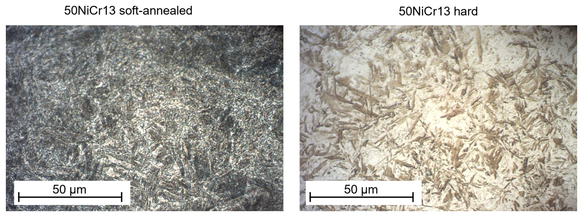
Figure 2Microstructure of the soft-annealed and hardened 50NiCr13 at 1000 times magnification.
Regarding the sensor performance of a steel, its remanent flux density Br, magnetostriction constant at saturation λs, and coercive field Hc are important. A suitable material should show large values of Br, as that also increases the flux density accessible externally by the secondary sensors, separating it more easily from disturbing influences such as the geomagnetic field and leading to better sensor stability and accuracy.
High saturation magnetostriction constants λs normally contribute to a more significant change in the secondary sensor signal, hence improving the sensor sensitivity. It is worth mentioning here that high values of λs alone do not necessarily yield a good sensor performance, as in some materials λ as a function of the magnetic field strength H is not a strictly monotonic curve. Iron and therefore also some lowly alloyed steels show a reversal of λ over H curve, the so-called Villari reversal (Lange and Jaensch, 1964). More relevant for sensors, the inversion also applies, as such materials show a non-monotonic dependence on their remanent magnetization plotted over a mechanical load (Ewing, 1892). Primary sensors made of materials with such non-monotonic behaviour would lead to partially low sensitivity or even ambiguous sensor readings, hindering reasonable application of the material.
The coercive field Hc defines the ability of a material to keep magnetization vectors stable even when they are exposed to fields that strive to change that magnetization. Such fields might originate externally from foreign sources of magnetic fields as well as internally from the desired change in magnetic flux caused by mechanical stress due to the Villari effect (Atherton and Jiles, 1983). Hence, higher values of Hc improve the stability of the transfer function, reducing hysteretic effects as shown later.
It is important to mention that these magnetic material properties do not directly define the sensor performance but mutually influence each other. For example, a high magnetostriction λ alone will not improve a sensor's sensitivity and accuracy if the coercive field is not large enough to keep the remanent magnetization sufficiently stable under all load conditions.
With α iron being the major constituent of commonly employed ferritic steels at operation temperature, they show ferromagnetic behaviour. The magnetic properties of such a material vary strongly with the material composition and its microstructure, as discussed for instance in Ewing (1892) or Cullity and Graham (2009). Regarding the microstructure, the heat treatment that the material has undergone, its residual stresses, its impurities, and its dislocations caused by plastic deformation significantly impact the magnetic properties (Lange and Jaensch, 1964; Sablik, 2001). For that reason, comparing measuring data is difficult when samples are obtained from forming or machining without successive heat treatments, causing a complex residual stress condition or an undefined microstructure. In this regard, this paper does not intend to provide measurements absolutely matching any standardized sample specimen, but it intends to compare materials relative to one another under a realistic engineering condition to explain the observed sensor performance.
One of the considered steels is 50NiCr13, a commonly available cold work tool steel. The material's suitability for this sensor concept is investigated under its soft-annealed and hardened heat treatment conditions. The soft-annealed material did not undergo a normalizing heat treatment after machining, as discussed above. The hardened samples have been oil-quenched and have not been annealed after hardening. These two conditions are supposed to mark the two distant ends of the possible hardness scale. The microstructure of both heat treatment conditions of sample rods with a diameter of 10 mm is shown in Fig. 2 at 1000 times magnification.
Both microstructures deviate significantly, with a large portion of pearlitic domains in the case of the soft-annealed sample to the left and martensitic structures in the hardened sample to the right. As magnetic hardness and mechanical hardness correlate (Steinmetz, 1892), the strongly distorted iron lattice of the hardened, martensitic microstructure is expected to exhibit higher values of the coercive field and, at the same time, a lower remanent flux density. This is confirmed by the magnetic hysteresis loops shown in Fig. 3 and measured at sample rods 10 mm in diameter according to the method defined by DIN EN 60404-4 (Deutsches Institut für Normung e.V., 2009). In addition to DIN EN 60404-4, the sample rods have been loaded with tensile and compressive forces in the axial rod direction to investigate the impact of the Villari effect on the magnetic properties.
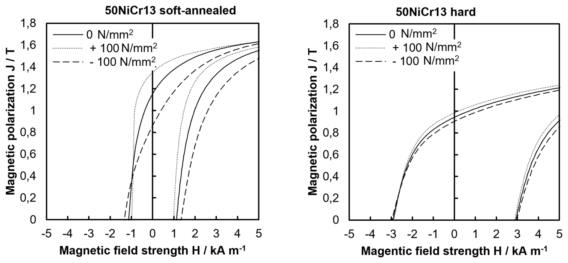
Figure 3Magnetic hysteresis loops of the soft-annealed and hardened steel 50NiCr13 measured according to DIN EN 60404-4 under tensile and compressive loads as well as under unloaded conditions.
While the soft material in an unloaded condition shows a coercive field of 1.13 kA m−1 and a remanent flux density of 1.15 T, hardening increases the coercive field to 2.92 kA m−1 and decreases the remanent flux density to 0.94 T. Under a tensile load, the curves of both heat treatment conditions shown in Fig. 3 erect, as expected from a material with positive magnetostriction, while they flatten under compressive stress (Hinz and Voigt, 1989). From the perspective of the present sensor concept, the change in the remanent flux density under a load is crucial as it affects the sensor sensitivity. In the case of the soft-annealed material, the remanent flux density Br varies from 0.86 to 1.35 T and the hard material covers a span from 0.91 to 0.98 T over the presented load range. Equation (1) defines a simple fraction fm to briefly compare materials and their heat treatment conditions regarding their potential sensitivity behaviour.
For the hardened condition of the considered steel, fm results in 0.35 mT mm2 N−1, while in a soft-annealed state it rises significantly to 2.45 mT mm2 N−1. Again, fm alone does not define the sensor's sensitivity, as its coercive field and the shape of the λ curve also take effect, as will be shown later.
The coercive field of both presented heat treatment conditions varies slightly under load, but this effect is considered to be insignificant with regard to the sensor performance.
4.1 Test setup
In view of the above-mentioned potential field of application, the pre-load measurement of bearing arrangements, the sensor concept was evaluated in a test setup simulating such a pre-load setting process as shown in Fig. 4.
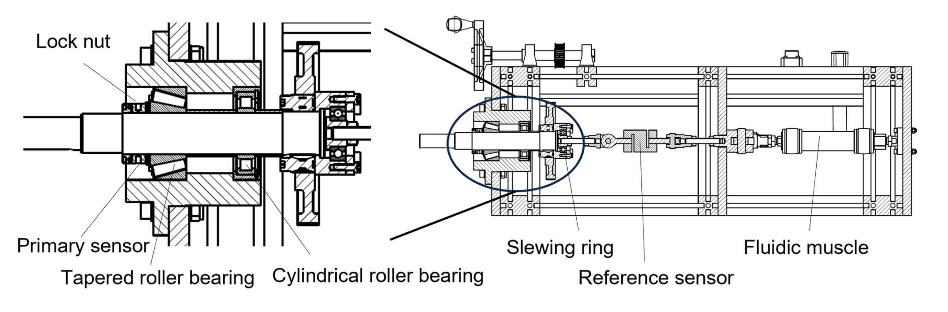
Figure 4A cross-sectional view of the test rig and a close-up of the primary sensor position.
The 60 mm outer diameter primary sensor disc is spaced between the tapered roller bearing's inner ring and the lock nut used to set the pre-load of the bearing arrangement. Unlike a real-life pre-loaded bearing arrangement, the test rig replaces the counter bearing on the right side with a cylindrical roller bearing to enable a precise reference measurement with a strain gauge reference sensor. The reference sensor measures a force of up to 10 kN with a specified precision of 0.1 % of the full scale, which is considered sufficiently precise not to distort the findings of the present sensor concept characterization. Two fluidic muscles at the right end of the test rig enable a controlled loading of the whole pull arrangement.
Two secondary sensors are received by one recess of the primary sensor disc near opposite measuring edges, as shown when including the sensor designation and coordinate systems in Fig. 5. This arrangement is applied in the opposite recess as well, leading to a total of four secondary sensors that are read out synchronously.
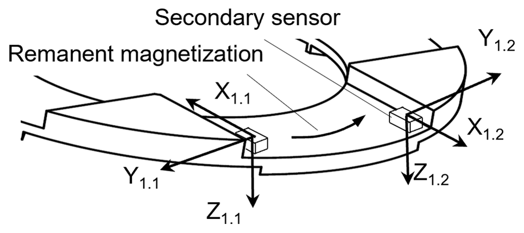
Multiple potential secondary sensors are available in standard surface mount device packages based on the anisotropic magnetoresistive (AMR), giant magnetoresistive (GMR), or hall effect that cover a wide span of measuring ranges (Tumanski, 2011). As the secondary sensor's impact on the overall sensor performance is currently expected to be significantly lower compared to the primary sensor, investigating such secondary sensors and their behaviour is not part of this work. For the presented measurements, AMR sensors independently measuring three orthogonal axis directions serve as secondary sensors, totalling 12 dedicated secondary sensor signals.
4.2 Sensor measurement results and discussion
The transfer function of the force sensor is obtained by stepwise increasing the load on the primary sensor from a starting pre-load, as pre-loading is a common way of improving linearity (Talebian, 2022). The load profile does not involve intermediate unloading between the load steps as the diagrams in Fig. 6 show with exemplary chosen secondary sensor signals, all referred to their non-zero starting values. The soft-annealed and hard materials both show signals with reasonable correlation with the reference force, e.g. 1.2 y in the case of soft-annealed steel and 1.1 y for the hardened version. However, other secondary sensor signals exhibit only a weak correlation, such as 1.1 z in the soft-annealed material and 1.2 y in the hardened version. The factors that cause such a weak correlation have not yet been fully explored. Local material inhomogeneities, uneven load distributions, or positioning errors of the secondary sensors might be potential root causes.
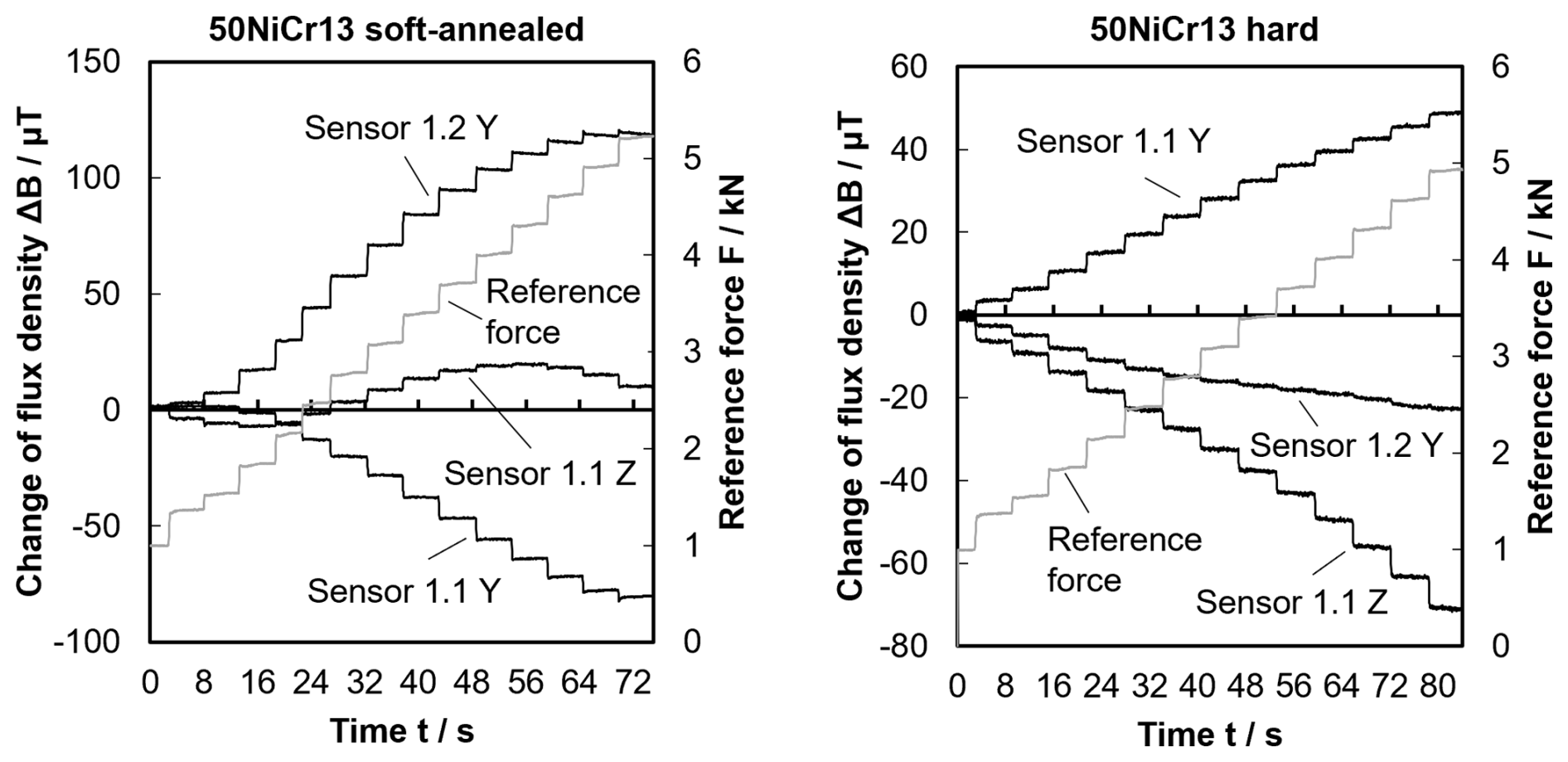
Figure 6Examples of secondary sensor signals in response to a stepwise increase in the sensor load.
When comparing signals with reasonable correlation between the two heat treatment conditions, larger total changes in the flux density can be observed in soft-annealed steel compared to hardened steel, e.g. approx. 120 µT for 1.2 y and soft-annealed vs. approx. 50 µT for 1.1 y and hardened. This confirms the generic relation mentioned in Sect. 3, according to which materials with larger changes in remanent flux density under load, i.e. larger factors fm, provide higher signal sensitivity. However, Fig. 6 also shows that an increased factor fm does not proportionally translate into an increase in sensitivity, as counter-effects hinder that. Amongst other factors, unstable remanent magnetization vectors due to a low coercive field of the soft-annealed material can be responsible for this. Furthermore, for the same reason secondary sensor signals show a saturating behaviour in soft-annealed primary sensors in areas of high loads above 4 kN.
If changes in remanent magnetization happen under loads and such a process is not fully reversible (Ewing, 1892; Atherton and Jiles, 1983), this will lead to a hysteretic transfer function. The stepwise load increase as shown in Fig. 6 might be useful for determining a transfer function, but it does not reveal these hysteretic problems and does not necessarily represent a reasonable application load profile. Here, cyclic loading with intermediate unloading is more useful and will reveal possible hysteretic effects better when plotting the secondary sensor response and load, as Fig. 7 shows. To obtain these curves, the sensors are loaded with five equidistant load levels from the starting pre-load 1 to 5 kN, followed by unloading them down to the starting pre-load, with each cycle repeated two times. The different signs of the signals under loads are caused by different positioning of the secondary sensors.

Figure 7Secondary sensor response for stepwise loading from 1 to 5 kN with intermediate unloading.
The secondary sensor signals obtained from the soft-annealed primary sensor show significantly stronger hysteretic behaviour due to the lower coercive field as presented in Sect. 3. Also, the drift of the readings at a low starting pre-load after undergoing the high load cycles of almost 30 µT is significantly more severe in the soft-annealed material compared to its hardened counterpart, even though a slight drift is still noticeable there. Figure 7 implies that hardening improves the hysteretic behaviour of the transfer function at the expense of signal sensitivity.
As the sensor concept enables the final approximation of the imposed load based on more than only one secondary sensor signal, the impact of hysteresis on the overall precision also depends on other secondary sensor signals that are assessed. As the curves shown in Fig. 7 exhibit a non-linear shape, a second-order polynomial regression function is chosen according to Eq. (2) to approximate the acting load by combining several secondary sensor signals.
The terms By,0 and Bz,0 in Eq. (2) determine the secondary sensor readings under a pre-loaded starting condition, and the parameters βy,i and βz,i are obtained by minimizing the approximation error based on transfer function data collected according to Fig. 6. Disregarding secondary sensor signals that do not show proper correlation as discussed above can be achieved by setting the corresponding parameters β to zero. In the present case, choosing for example signals 1.1 y and 1.2 y with the soft-annealed primary sensor and 1.1 y and 1.1 z for the hard version and disregarding other signals seems to be reasonable based on the previous considerations. When applying the same load profile that led to the diagrams in Fig. 7, approximating the acting force according to Eq. (2) yields the load curves of Fig. 8.
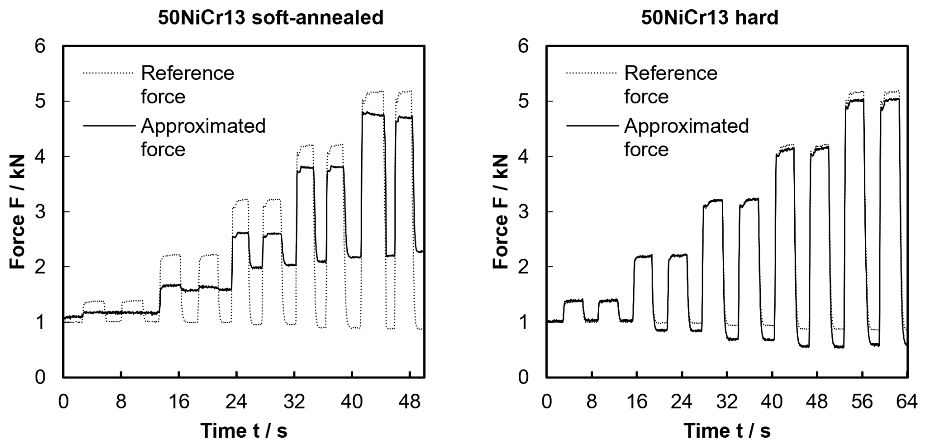
Figure 8Resulting approximation of the acting load for primary sensors made of the soft-annealed and hard steel 50NiCr13.
In the case of the soft-annealed primary sensor, the approximated force values deviate significantly from the reference measurements of the strain gauge reference sensor, and a severe drift of the low load approximation is noticeable. These findings do not allow a reasonable application of such a sensor material. In the case of the hardened material, deviations from the reference values and a low load drift are also noticeable, though to a significantly smaller extent, as the signal plots in Fig. 7 already indicate. In the high-load area at around 5 kN, the approximated values differ by a maximum of 3.4 % from the reference value.
The suitability of such precision depends on the considered application. Pre-load measurement as mentioned in the beginning could be a suitable application where the present sensor concept with its limited precision might still provide added value over existing pre-load measurement techniques (Li et al., 2020), as the expectable precision of current industrially applied methods is moderate (Hwang and Lee, 2010). The low package height and reduced costs of the sensor concept could be major enablers compared to strain gauge or piezo-based sensor techniques.
The investigations into the presented sensor concept show that force measurement based on the inverse magnetostrictive principle with remanent magnetization is basically possible even without the usage of active field-generating means. However, the currently achievable precision and stability are lower compared to the performance exhibited by strain gauge sensor systems.
The magnetic properties of the employed sensor material, foremost its coercive field and its remanent flux density under load, have a direct impact on the hysteretic behaviour and precision of the sensor. Heat treating a material can alter these values, but the desired increase in the coercive field often involves a weaker magnetostrictive behaviour, leading to a trade-off in the choice of material. Further investigations into mechanical engineering steel grades and their magnetic properties as well as optimizations of the primary sensor geometry might lead to improvements.
The present investigations have not yet taken disturbing effects such as the geomagnetic field and temperature impacts into consideration, even though their impact is expected to be relevant. Such effects should be analysed in future work, ideally based on a specific application environment.
This paper does not use data other than those presented in Figs. 3, 6, 7 and 8.
MH designed and implemented the test rigs, prepared the samples, performed the measurements, and prepared the measurement data. AH defined the concept of the test rigs, the experiments, and the concept of the paper. He wrote the paper and revised it.
Alexander Hofmann is named as an inventor on patent applications filed by the Technical University of Applied Sciences Würzburg-Schweinfurt that are related to the presented topic. The authors are not aware of competing interests other than this.
Publisher's note: Copernicus Publications remains neutral with regard to jurisdictional claims made in the text, published maps, institutional affiliations, or any other geographical representation in this paper. While Copernicus Publications makes every effort to include appropriate place names, the final responsibility lies with the authors.
This article is part of the special issue “Sensors and Measurement Systems 2024”. It is a result of the 22. GMA/ITG Fachtagung Sensoren und Messsysteme 2024, Nuremberg, Germany, 11 to 12 June 2024.
The authors would like to thank the Bavarian Ministry of Economic Affairs, Regional Development and Energy for funding the project.
This research was supported by the Bavarian Ministry of Economic Affairs, Regional Development and Energy through grant no. VAL-2202-0002 in the framework of the Bavarian funding programme for the validation of research results and inventions (VAL). This publication was supported by the publication fund of the Technical University of Applied Sciences Würzburg-Schweinfurt.
This paper was edited by Rainer Tutsch and reviewed by two anonymous referees.
Atherton, D. L. and Jiles, D. C.: Effects of stress on the magnetization of steel, IEEE T. Magn., 19, 2021–2023, 1983.
Cullity, B. D. and Graham, C. D.: Magnetostriction and the Effects of Stress, in: Introduction to Magnetic Materials, 2nd Edn., Wiley, New York, USA, 241–273, https://doi.org/10.1002/9780470386323, 2009.
Deutsches Institut für Normung e.V.: Magnetische Werkstoffe-Teil 4: Verfahren zur Messung der magnetischen Eigenschaften von weichmagnetischen Werkstoffen im Gleichfeld, DIN EN 60404-4:2009-08, 2009.
Ewing, J. A.: Magnetische Induktion in Eisen und verwandten Metallen, Deutsche Ausgabe, Springer Verlag, Berlin, Germany, https://doi.org/10.1007/978-3-642-91101-9, 1892.
Hofmann, A. and Heusinger, M.: Neues Sensorkonzept für magnetostriktive Kraftmessung in kostenorientierten Anwendungen, in: 22. GMA/ITG-Fachtagung Sensoren und Messsysteme 2024, Nürnberg, Germany, 11–12 June 2024, 45–51, https://doi.org/10.5162/sensoren2024/A2.1, 2024.
Hinz, G. and Voigt, H.: Magnetoelastic Sensors, in: Sensors: Magnetic Sensors Vol. 5, edited by: Boll, R. and Overshott, K. J., VCH, Weinheim, Germany, 97–152, https://doi.org/10.1002/9783527620166.ch4, 1989.
Hwang, Y. K. and Lee, C. M.: A review on the preload technology of the rolling bearing for the spindle of machine tools, Int. J. Precis. Eng. Man., 11, 491–498, 2010.
Joule, J. P.: On a new class of magnetic forces, Ann. Electr. Magn. Chem., 8, 219–224, 1842.
Kleinke, D. K. and Uras, H. M.: A magnetostrictive force sensor, Rev. Sci. Instrum., 65, 1699–1710, https://doi.org/10.1063/1.1144863, 1994.
Lange, H. and Jaensch, P.: Die Magnetostriktion in Abhängigkeit von der Magnetisierung, in: Forschungsberichte des Landes Nordrhein-Westfalen, Nr. 1293, Westdeutscher Verlag, Köln und Opladen, Germany, https://doi.org/10.1007/978-3-663-07019-1, 1964.
Li, T., Kolar, P., Li, X. Y., and Wu, J.: Research Development of Preload Technology on Angular Contact Ball Bearing of High Speed Spindle: A Review, Int. J. Precis. Eng. Man., 21, 1163–1185, 2020.
Muro, H., Saito, C., Shimada, M., and Furuya, Y.: Magnetostrictive-ring type torque sensor using two Hall ICs with differential magnetic field detection, in: IEEE Sensors 2014, Valencia, Spain, 2–5 November 2014, 412–415, https://doi.org/10.1109/ICSENS.2014.6985022, 2014.
Sablik, M. J.: Modeling the effect of grain size and dislocation density on hysteretic magnetic properties in steels, J. Appl. Phys., 89, 5610–5613, https://doi.org/10.1063/1.1359167, 2001.
Schiessle, E.: Magnetoelastische Sensoren, In: Industriesensorik – Sensortechnik und Messwertaufnahme, 2. Auflage, 253–263, Vogel, Würzburg, Germany, 2016.
Steinmetz, C. P.: On the law of hysteresis, Trans. Am. Inst. Elec. Engrs., 9, 3–64, 1892.
Talebian, S.: Theoretical and experimental study on optimum operational conditions of a magnetostrictive force sensor, J. Magn. Magn. Mater., 562, 169847, https://doi.org/10.1016/j.jmmm.2022.169847, 2022.
Tumanski, S.: Handbook of magnetic measurements, CRC Press, Boca Raton, USA, ISBN 978-1-4398-2951-6, 2011.
Villari, E.: Ueber die Aenderungen des magnetischen Moments, welche der Zug und das Hindurchleiten eines galvanischen Stroms in einem Stabe von Stahl oder Eisen hervorbringen, Ann. Phys., 202, 87–122, 1865.