the Creative Commons Attribution 4.0 License.
the Creative Commons Attribution 4.0 License.
 | 18 Mar 2026
Adaptive accuracy enhancement for a simultaneously firing optical position sensor
Eduard Burian
An algorithm for adaptive accuracy enhancement of lateral position sensing based on quadrature spatio-temporal modulation is presented, and its application in a prototype micropower optical position sensor with simultaneously firing infrared emitters is reported. Substantial (4×) improvement in measurement accuracy over a basic detection method has been observed using an automated test stand where partial incapacity on one of the emitter channels has been simulated.
- Article
(1569 KB) - Full-text XML
- BibTeX
- EndNote


A micropower active optical position sensor measuring one-dimensional displacements lateral to the optical axis over decimeter-wide gaps has recently been presented (Burian, 2023). Quadrature spatio-temporal modulation involving four simultaneously firing infrared emitters and a diffuse reference primer has been utilized in order to reduce the ON time for signal processing circuitry, allowing up to 2 years of continual battery operation. However, variations in the geometry of emitters due to the manufacturing process, as well as degradation of the primer due to industrial conditions and aging, may result in worsening readout accuracy. To address both issues, an adaptive algorithm for the determination of gains and crosstalk in a signal path involving emitters, a primer, and acquisition circuitry has been proposed and implemented in firmware of the prototype device. In this paper, a theoretical background comprising an adaptive displacement detection algorithm and results obtained with an automated test stand with a linear drive and precision position readout are laid out.
Methods for minimizing quadrature detection errors are routinely applied in a wide field of linear and angular position measurement techniques, including in resolvers, optical encoders, and magnetic encoders, as well as in optical interferometry, particularly interferometric position sensors (Berkovic and Shafir, 2012). A traditional approach for the parameterization of elliptical distortion in interferometer output is Heydemann's correction (Heydemann, 1981). More recently, harmonic calibration techniques (Ferrero and Bellon, 2022) have gained ground, utilizing sinusoidal input for the determination of higher-order nonlinearities, improving corrections to quadrature errors beyond elliptical distortion. While optical interferometry lies in a somewhat distant realm from the investigated position-sensing method, we can still compare the performance of applied corrections in the relative improvement of the position readout. A similar comparison has been made for performances of calibration methods developed for a similar field of analog resolvers and sinusoidal encoders. The comparison of accuracy gains observed for particular correction methods and a discussion on the performance and limits of our algorithm are also laid out in this paper.
The lateral-position-sensing method implemented in the prototype device (Fig. 1) is based on spatio-temporal modulation involving four infrared emitters equipped with collimating lenses, simultaneously illuminating a reference primer pattern in four distinct spots with mutual spatial phase shifts of 90° (Fig. 2). The pattern, printed on a diffuse strip, is numerically optimized into the specific “Copacabana” shape to minimize harmonic distortion in the modulation of the reflected light.
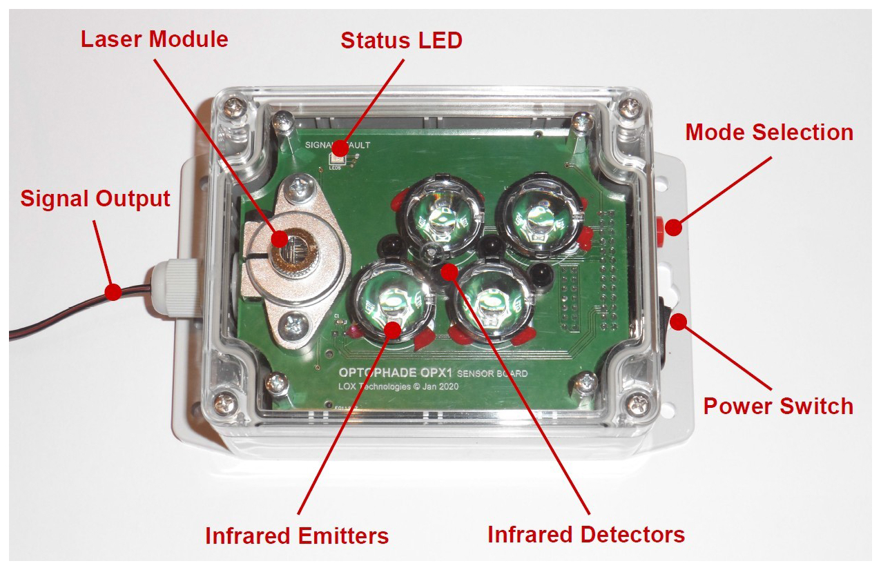
Figure 1Prototype position sensor with four collimated IR emitters under an acrylic cover. The laser module is solely for the adjustment of the sensor optical axis.
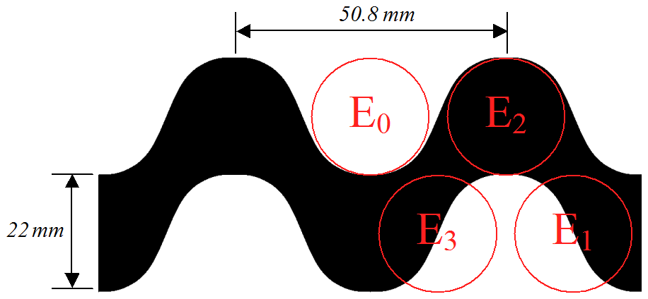
Figure 2Two spatial periods of the reference “Copacabana” primer with an indication of emitter positions at the zero spatial phase.
The principle of position sensing is illustrated in Fig. 3. At the emitter side, a reference oscillator is gated for a defined time interval to provide four phase-shifted current bursts supplied to infrared LED emitters. Incident light is then modulated and reflected depending on the lateral displacement of the sensor relative to the primer pattern. As a result of the spatial modulation, a temporal phase shift to the overall reflected light is induced, revealing lateral displacement within one spatial period. Reflected light received in a set of infrared detectors is amplified, converted, and synchronously detected in the digital domain, resulting in a complex value with a phase angle directly proportional to the lateral displacement of the primer. Finally, differences in the detected phase are re-integrated to provide position information, limited solely by the length of the primer strip.
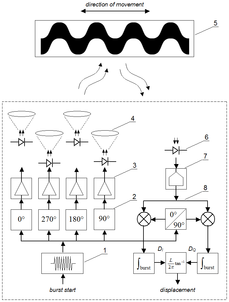
Figure 3Principle of operation. Oscillator (1) gated for defined burst length provides reference frequency for phase shifters (2) and for synchronous detector (8). Sources (3) supply phase-shifted current bursts to infrared LED emitters equipped with collimator lenses (4), simultaneously illuminating the primer pattern (5) in four distinct spots. Overall reflected light is then sensed in a photodiode array (6), amplified, and converted within an acquisition circuitry (7) and synchronously detected within the digital domain. The phase of the complex detector output, scaled to length per radian, provides measured displacement of the primer within one spatial period.
Because of irregularities in emitter circuitry and collimator geometries, as well as due to aging and field conditions, detected in-phase and quadrature components can face irregular distortion observed as affine (shift, scale, ev. rotation) transformation on a complex plane. This distortion leads to phase errors and consequently to position measurement errors, with reported magnitudes of 0.5–1.2 mm for sensing gaps of 25–185 mm (Burian, 2023). To account for the irregularities, a model for spatio-temporal modulation and a subsequent synchronous demodulation process with distinct channel gains is introduced as
where D is the detector output; Gn>0 is the arbitrary (presumably known) gain for the nth channel; and is the biased cosine function supplying both spatial and temporal intensity modulation, governed by spatial and temporal modulation phases and with periods L and T, respectively. After the separation of spatio-temporal modulation from channel-dependent phase shifts and integration over time, we obtain
where is the spatial modulation factor dependent on displacement l.
The terms in Eq. (2) suggest that the set of detected values can be geometrically interpreted as a complex-plane ellipse, with offset and eccentricity given by irregularities in channel gains. With regard to the identity, Eq. (2) can be solved as a pair of first-order algebraic equations, which for the given detector output D result in
with evident contributions of channel gain values in offset and scale corrections to the detector output.
The measured relative lateral position l can then be evaluated by re-integrating changes in the phase of the found spatial modulation factor using
where the last expression maintains the numerical stability of re-integration for differences smaller than .
To reveal information about actual channel gains, the terms in Eq. (2) can be isolated by utilizing Fourier analysis of the detector output at basic spatial frequencies. The Fourier components for can be found as integrals
evaluated numerically for one or multiple spatial periods. This of course implies that the sensor moves relative to the primer for at least one length L. Applying Fourier transformation to the terms in Eq. (2), we obtain
and
By solving Eqs. (6)–(8), we get enhanced approximations to gains as
Enhanced channel gain values can then be supplied as gains in Eq. (3) for evaluation of the next set of position values, resulting in a lesser position-sensing error, which in turn leads to more accurate integration of Fourier components. This process consecutively leads to the enhancement of position accuracy and adaptation of gains for changing field conditions.
Further irregularities in emitter/collimator geometries can result in channel crosstalk, observable as unwanted correlation between real and imaginary components of the detector output. To address this issue, we resorted to rotation of the detector signal prior to gain correction. The crosstalk error is detected as an anomalous imaginary part in the C−1 component, and the correction angle that provides detector output rotation is accumulated according to the formula
with kθ≅0.02 maintaining stable results.
To assess the performance of the proposed detection algorithm, an automated test stand with a linear drive and precision position measurement has been readied (Fig. 4). A 400 mm wide primer strip glued to a separate plane, allowing configurable sensing gap distances, enabled an effective sensor travel length of >6L. Serial data from the tested optical position sensor and precision position reference with 0.01 mm resolution have been fused in the drive control unit and captured in a PC application with a 10 Hz rate.
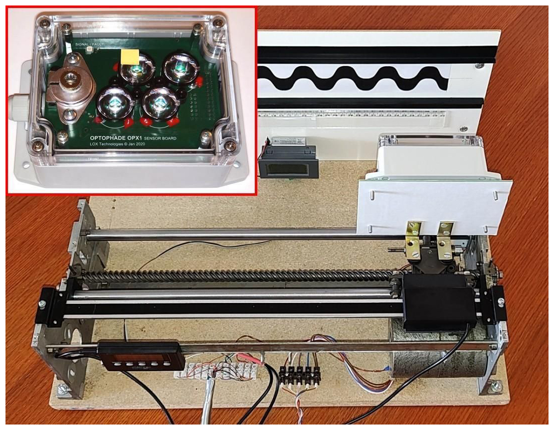
Figure 4Automated test stand. Inset image: Front side of tested optical sensor with simulated incapacity.
In approx. 30 min, the test performed at a 125 mm sensing gap distance, and sensor incapacity was simulated by partially blocking one of the emitter channels. The captured complex detector values forming a circular trajectory are shown in Fig. 5, and results for the sensor position measurement error and performance of the gain adaptation algorithm can be seen in Figs. 6 and 7.
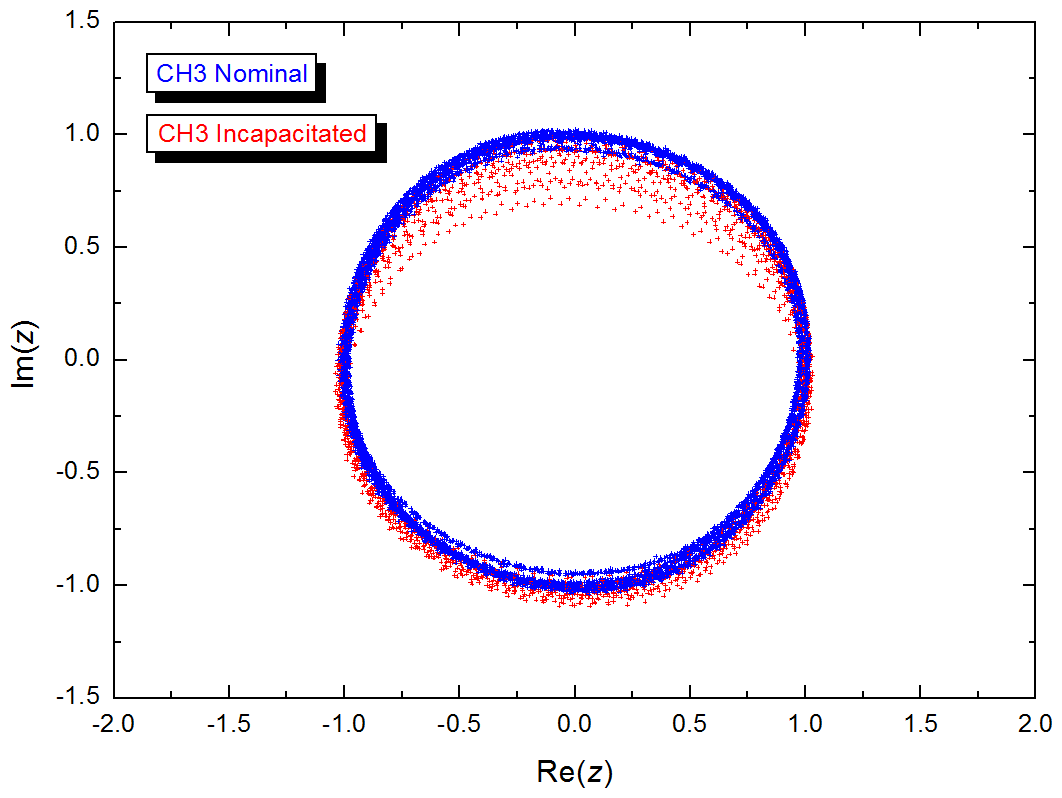
Figure 5Complex plot of gain- and crosstalk-corrected synchronous detector output for nominal and incapacitated regimes.
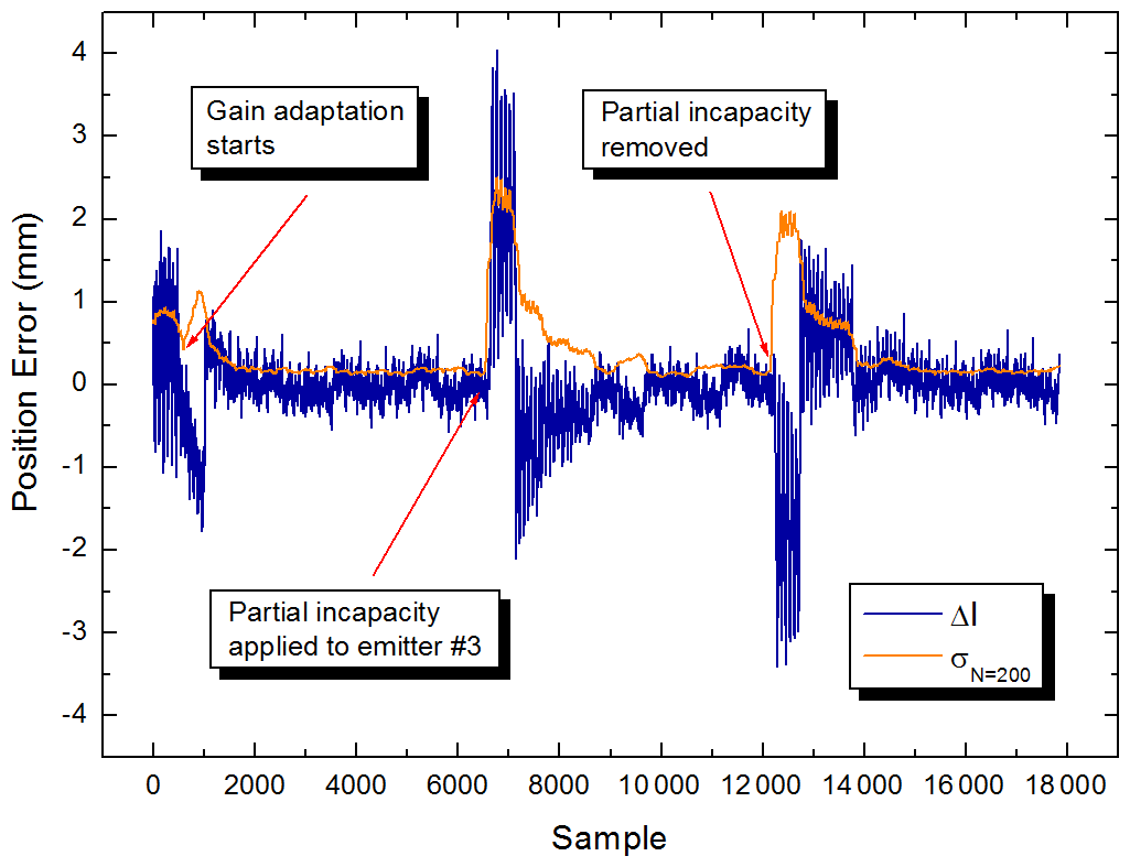
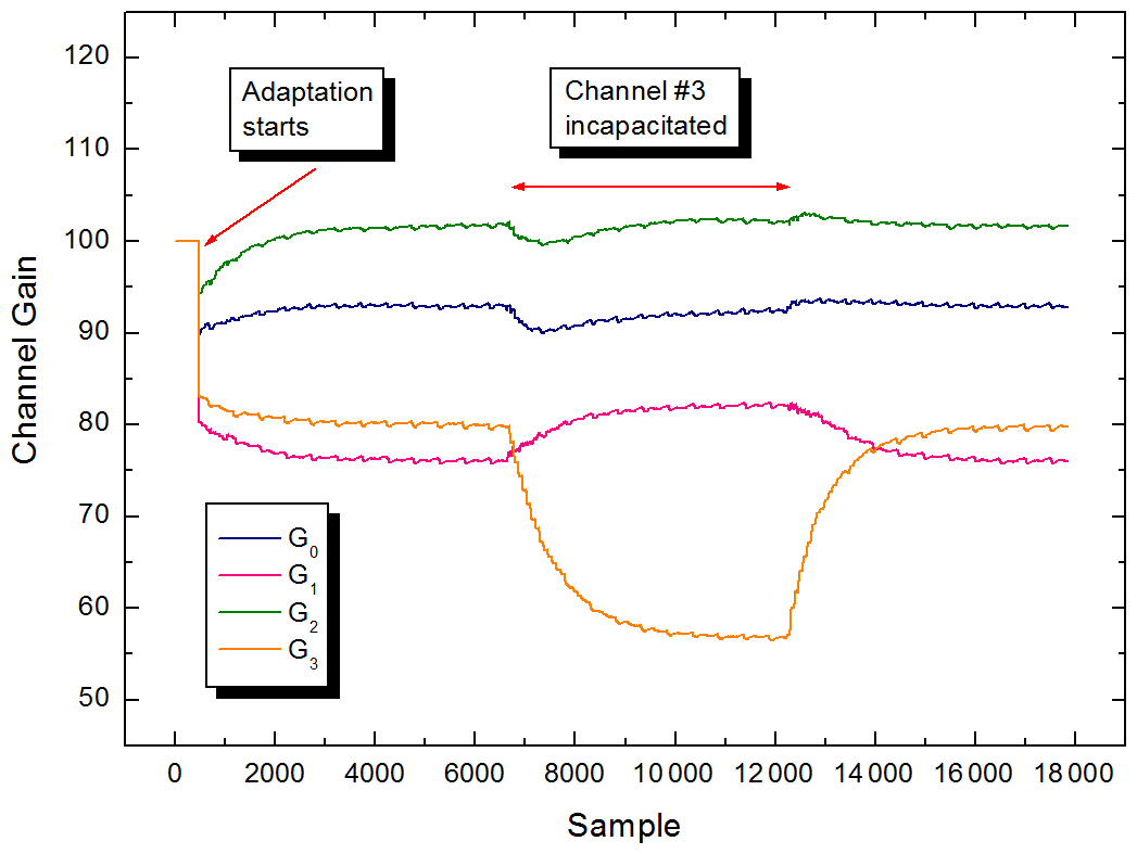
Figure 7Adaptation of channel gains with indication of initial and channel incapacity conditions.
Initially, as gains were set to equal values of 100, a standard position error of 0.8–1 mm is indicated. Later, with a sufficient amount of detector data integrated, adaptation of gains started, resulting in a gradual enhancement in position accuracy to less than 0.2 mm. At that point, the corrected detector data showed minimal deviation from the unit circle (blue dots in Fig. 5).
In the next phase, we used a 1 cm2 paper strip to partially block one of the infrared emitters, simulating the possible effect of harsh field conditions on sensor optics (inset image in Fig. 4). The subsequent elliptical distortion in the plot of detector data (red dots in Fig. 5) and a surge in measurement error to approx. 10× the nominal value could be observed; however, as channel gains adapted, distortion and measurement error dropped again to almost the previous levels. The adaptation process took approx. 5 min (3000 iterations) to reach 90 % of the settled gain values, with the strongest response at the incapacitated emitter channel (Fig. 7). A similar behavior with return to original settled levels could be observed after strip removal.
In Table 1, reported results in the improvement of position readout errors for a range of sensor techniques are listed and compared with the presented approach. As a measure of performance, we first calculated the percentage of reported uncorrected and corrected position residuals (if available) relative to the principal pitch of the physical medium (half wavelength for interferometry or one circle for angular resolvers). Then, the correction performance coefficient is calculated as a ratio of the residual values.
Table 1Performances of corrections to quadrature detection distortion for various types of position sensing (HD – Heydemann, MRWLS – modified recursive weighted least squares, FB – Fourier based, ANN – artificial neural network).
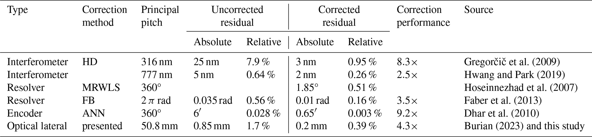
While some of the listed least-squares and multi-parametric methods offer better relative residual and correction figures, the presented correction method based on online computation of three basic Fourier components shows rather solid performance, without the need to resort to extensive computation resources found in advanced DSP or FPGA devices. The approach can present an advantage, particularly in low-power and low-cost sensor segments.
A particular bottleneck of our detection method lies in the necessity for adjustment of the optical axis to the center of the primer pattern. While slight cross shifts resulting in elliptical distortion will be corrected in the adaptation process, offsets larger than of the primer width lead to breakdown of the method. Thus, our intention for future work is to investigate the usability of more robust patterns, like simple vertical and diagonal stripes, which might lead to more complex Fourier-based correction algorithms as well. Another topic for future investigation is the robustness of the method against larger degradation of the integrity of the primer, like ruptures and aging-related loss of contrast.
In this paper, we proposed a modification to a basic detection algorithm for a novel active optical position sensor based on quadrature spatio-temporal modulation. The adaptive algorithm has been found to be effective in maintaining both hardware-related and environmentally induced gain irregularities and channel crosstalk, enhancing the accuracy of position sensing down to 0.2 mm at >100 mm sensing gap distances. In comparison to methods applied for assessing quadrature-phase distortion in interferometric and resolver-based position sensing, where advanced solutions offer almost 10× improvement in readout accuracy, the presented method shows solid 4× accuracy gain without the need for larger computational resources.
Both the software code and the data are courtesy of LOX Technologies s.r.o. Data can be shared upon request to the author.
The author has declared that there are no competing interests.
Publisher's note: Copernicus Publications remains neutral with regard to jurisdictional claims made in the text, published maps, institutional affiliations, or any other geographical representation in this paper. The authors bear the ultimate responsibility for providing appropriate place names. Views expressed in the text are those of the authors and do not necessarily reflect the views of the publisher.
This article is part of the special issue “Eurosensors 2024”. It is a result of the EUROSENSORS XXXVI, Debrecen, Hungary, 1–4 September 2024.
This paper was edited by Péter Fürjes and reviewed by two anonymous referees.
Burian, E.: Micropower Active Optical Position Sensor for Decimeter-Range Sensing Gaps, in: 2023 IEEE SENSORS, IEEE, 1–3, ISBN 979-8-3503-0387-2, https://doi.org/10.1109/SENSORS56945.2023.10324868, 2023.
Berkovic, G. and Shafir, E.: Optical methods for distance and displacement measurements, Adv. Opt. Photonics, 4, 441–471, https://doi.org/10.1364/AOP.4.000441, 2012.
Dhar, V. K., Tickoo, A. K., Kaul, S. K., Koul, R., and Dubey, B. P.: Artificial Neural Network-based error compensation procedure for low-cost encoders, Meas. Sci. Technol., 21, 015112, https://doi.org/10.1088/0957-0233/21/1/015112, 2010.
Faber, J., Stulrajter, M., and Vittek, J.: Self-Calibration of the Resolver Sensor in Servo Drive Application, Commun.-Sci. Lett. Univ. Zilina, 15, 17–22, https://doi.org/10.26552/com.C.2013.2A.17-22, 2013.
Ferrero, B. and Bellon, L.: Harmonic calibration of quadrature phase interferometry, EPL, 139, 55002, https://doi.org/10.1209/0295-5075/ac8761, 2022.
Gregorčič, P., Požar, T., and Možina, J.: Quadrature phase-shift error analysis using a homodyne laser interferometer, Opt. Express, 17, 16322–16331, https://doi.org/10.1364/OE.17.016322, 2009.
Heydemann, P. L. M.: Determination and correction of quadrature fringe measurement errors in interferometers, Appl. Opt., 20, 3382–3384, https://doi.org/10.1364/AO.20.003382, 1981.
Hoseinnezhad, R., Bab-Hadiashar, A., and Harding, P.: Calibration of Resolver Sensors in Electromechanical Braking Systems: A Modified Recursive Weighted Least-Squares Approach, IEEE Trans. Ind. Electron., 54, 1052–1060, https://doi.org/10.1109/TIE.2007.893049, 2007.
Hwang, J.-H. and Park, C.-S.: Quadrature-detection-error Compensation in a Sinusoidally Modulated Optical Interferometer Using Digital Signal Processing, Curr. Opt. Photonics, 3, 204–209, https://doi.org/10.3807/COPP.2019.3.3.204, 2019.