the Creative Commons Attribution 4.0 License.
the Creative Commons Attribution 4.0 License.
 | 27 Jun 2019
Characterization, calibration and validation of an industrial emissometer
Elena Kononogova
Albert Adibekyan
Christian Monte
Jörg Hollandt
We report on the radiometric characterization and calibration of the TIR 100-2 (INGLAS Produktions GmbH, 2019) industrial emissometer. This instrument is used for handheld, on-site directional total emissivity measurements in industrial applications, e.g., the measurement of the emissivity of highly reflective thermal insulation materials. The diameter of the measurement field is determined by two different methods. The emissometer is calibrated with three different sets of low- and high-emissivity reference samples. Each calibration is validated by comparing the results of the TIR 100-2 to directional total emissivity results of the Emissivity Measurement in Air Facility (EMAF) at the Physikalisch-Technische Bundesanstalt (PTB), Berlin. Finally, the hemispherical total emissivity of highly reflective thermal insulation materials is determined using the TIR 100-2 according to the European Standard EN 12898, and, again, the results are validated with results obtained at the EMAF.
- Article
(5089 KB) - Full-text XML
- BibTeX
- EndNote


Reflective thermal insulation materials or reflective heat screens are used not only for building applications, but also in aircraft, land vehicles, boats, spacecraft, satellites, power plants, and cryogenic applications for thermal insulation and fire protection due to their light weight, small footprint, low particle contamination and high efficiency. The accurate knowledge of the emissivity of these materials is essential for their successful use and quality control as well as for the development and further improvement of new insulation products. Usually, infrared integrating-sphere-based spectrometers or hemispherical near-normal reflectometers with a hemispherical radiator are used for emissivity measurement in industrial applications and for the quality control of these materials (Hervea et al., 2012; Albaticia et al., 2013; van der Ham et al., 2014). However, the lack of appropriate calibration procedures and validated uncertainty budgets of end user's instruments has led to relatively large discrepancies in the emissivity measurements of highly reflective foils (Directive 2010/31/EU, 2010; expression by the CEN/TC 89/WG 12, 2017). This problem is addressed in the “Improvement of Emissivity Measurements on Reflective Insulation Materials” (EMIRIM) project (JRP EMIRIM, 2017), funded by the European Metrology Programme for Innovation and Research (EMPIR).
One of the tasks of the Physikalisch-Technische Bundesanstalt (PTB), as a partner in this project, is to characterize and validate emissivity measurement techniques and instruments for the reflective foils used in thermal insulation products. The TIR 100-2 emissometer, supplied by Inglas (INGLAS Produktions GmbH), was chosen for this project as it is one of the most commonly used commercial devices. Its technical features, i.e., the size of its measurement spot, was characterized at PTB using two independent measurement procedures. One of the two concepts is to observe a well-known reference sample through a set of highly reflective precision apertures with different diameters, which are placed in front of the emissometer in sequence. This approach is compared to scanning an aperture with a fixed size horizontally and vertically through the emissometer's field of view. Theoretical models are fitted to the results and both approaches are compared.
The calibration of the TIR 100-2 is based on measuring a calibration set consisting of two reference samples of known low and high emissivity. To find the most suitable set of reference samples for a specific application, the calibration procedure is performed with three different sets of reference samples. For the validation of the emissometer's performance with each specific set of reference samples the resulting emissivities measured with the TIR 100-2 are compared to the results obtained by the Emissivity Measurement in Air Facility (EMAF) at PTB. For this validation, emissivity measurements are performed on different highly reflective foils and highly emissive black coatings.
The TIR 100-2 emissometer (Fig. 1), made by Inglas, is a handheld, compact unit that can measure the directional total emissivity of nearly any surface (Table 1). The surface to be measured is subjected to the diffuse thermal radiation of the instrument's half-sphere-shaped blackbody operated at a temperature of 100 ∘C for a short amount of time. The diffuse illumination allows for the measurement of smooth as well as rough and structured surfaces. A fraction of the reflected radiation is imaged onto the thermopile radiation sensor through an opening in the blackbody radiator. The sensor looks through Fresnel optics from below at an angle of 12∘ from the perpendicular of the sample. The reflected infrared radiation measured by the sensor is converted to an absolute value of directional total emissivity by applying the calibration data of two reference samples belonging to the instrument. The result is displayed immediately on the touch screen of the device.
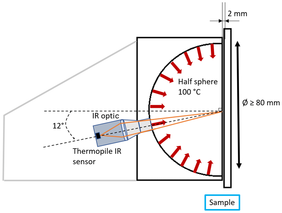
Figure 1Working principle of the TIR 100-2 (side view) for directional total emissivity measurement.
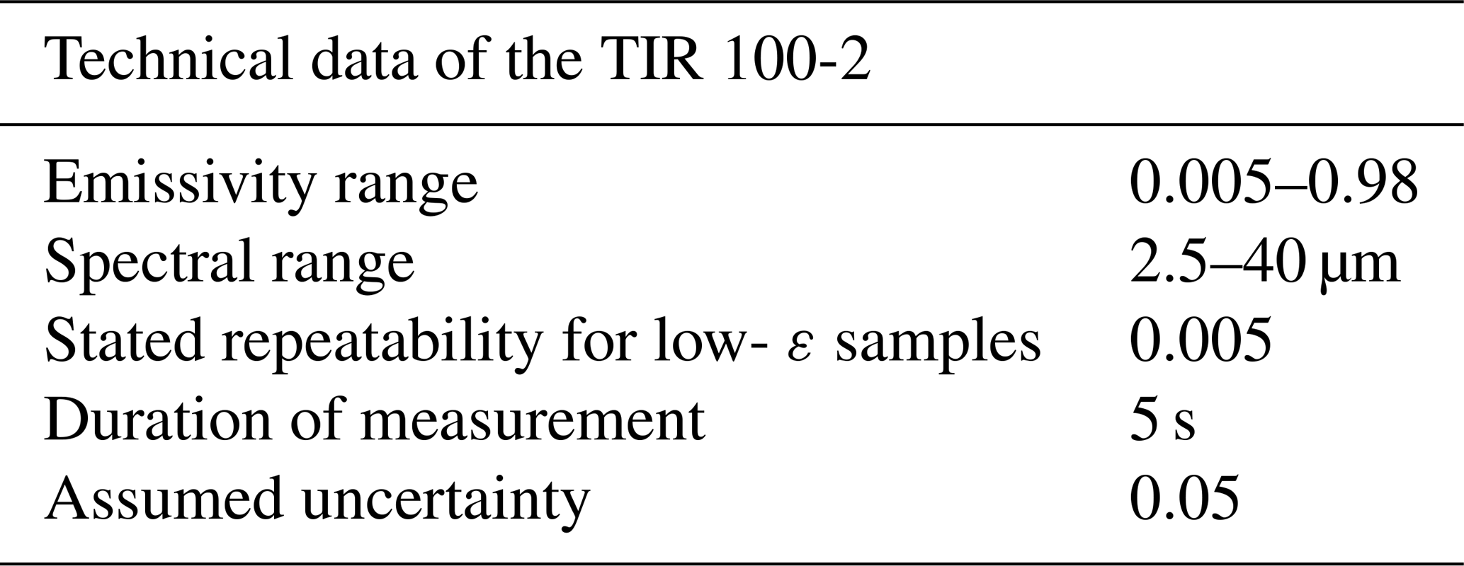
The emissivity and spectral range as well as the stated uncertainty for low-ε samples given in Table 1 are according to the technical documentation and communication with the manufacturer. The duration of measurement given is the typical time used for the measurements in this study. Longer measurement times yielded significant changes in the recorded emittance values due to sample heating. For the TIR 100-2, a standard uncertainty of 0.050 is assumed. Comparison measurements have shown that total hemispherical emissivities from 0.02 to 0.08 were measured for the same reflective foil with handheld instruments (CEN/TC 89/WG 12 N 209, 2013). Due to this variation, the lower limit of reliable measurable emissivities with these instruments is set to 0.05 by the CEN standard EN 16012 (CEN/TC 89/WG 12 N 209, 2013). Here, we assume this value as the uncertainty of the TIR 100-2 because other uncertainty information is not available.
Two complementary methods to determine the size of the measurement field of the TIR 100-2 were applied: the varied aperture method and the scanning aperture method. The TIR 100-2 and the samples were arranged on rail carriages, so that they could be precisely moved along an optical rail (Fig. 2). Also, the TIR 100-2 was mounted on a YZ stage made of two stacked linear stages. These stages provided 50 mm of travel and featured a side-mounted metric micrometer, respectively, which gave a 500 µm displacement for each revolution. Therefore, the emissometer could be moved and placed precisely in three directions.
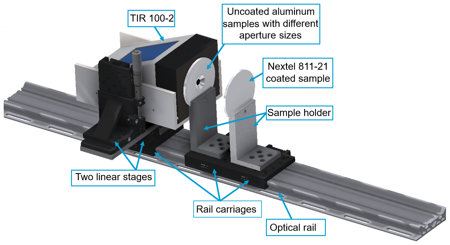
Figure 2Setup for characterization of the measurement field of the TIR 100-2. For the scanned aperture method, an aperture with a fixed diameter of 6 mm was used. For the varied aperture method, aperture diameters ranged from 1 to 32 mm.
3.1 Varied aperture method
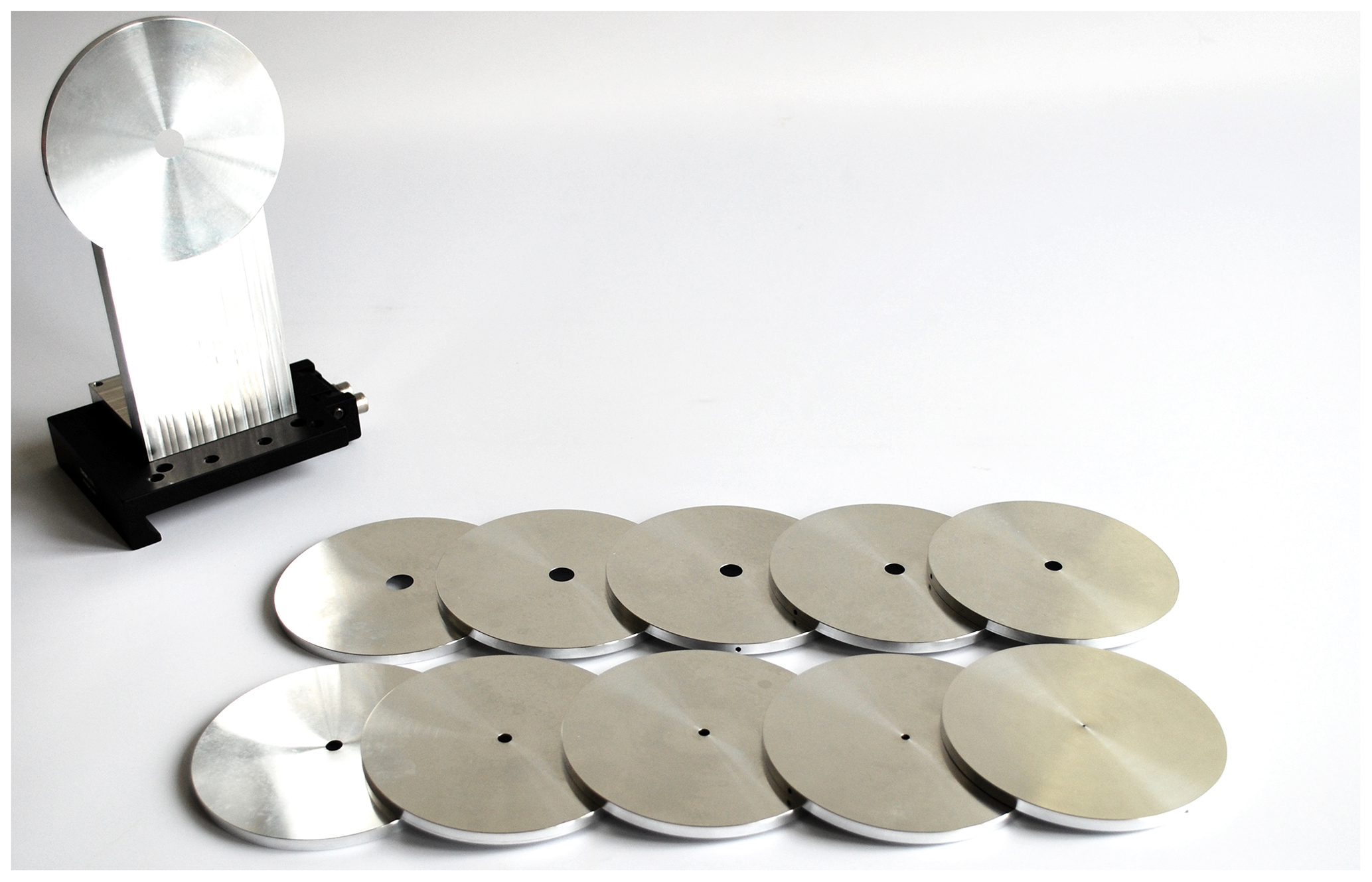
With the varied aperture method, measurements were made by placing a set of uncoated aluminum plates with central apertures of different sizes in front of the TIR100-2 in sequence (Fig. 3). Each aluminum plate had a hole in which a contact thermometer was placed. The temperature of the plate had to be monitored to assure that the plate itself did not significantly contribute to the radiation observed by the thermopile detector. Behind these aluminum plates, another plate coated with the highly emissive Nextel 811-21 paint was mounted at a distance of 55 mm. The aperture sizes applied ranged from diameters of 1 mm to 32 mm (Fig. 4). For the spot size measurement, the apparent emissivity of the combination of an aperture with the Nextel sample was recorded for each aperture size. One difficulty involved was positioning the aperture exactly in the center with respect to the collected beam. This was solved by using a plate holder design featuring a recess that exactly matched the outer diameter of the circular plates.
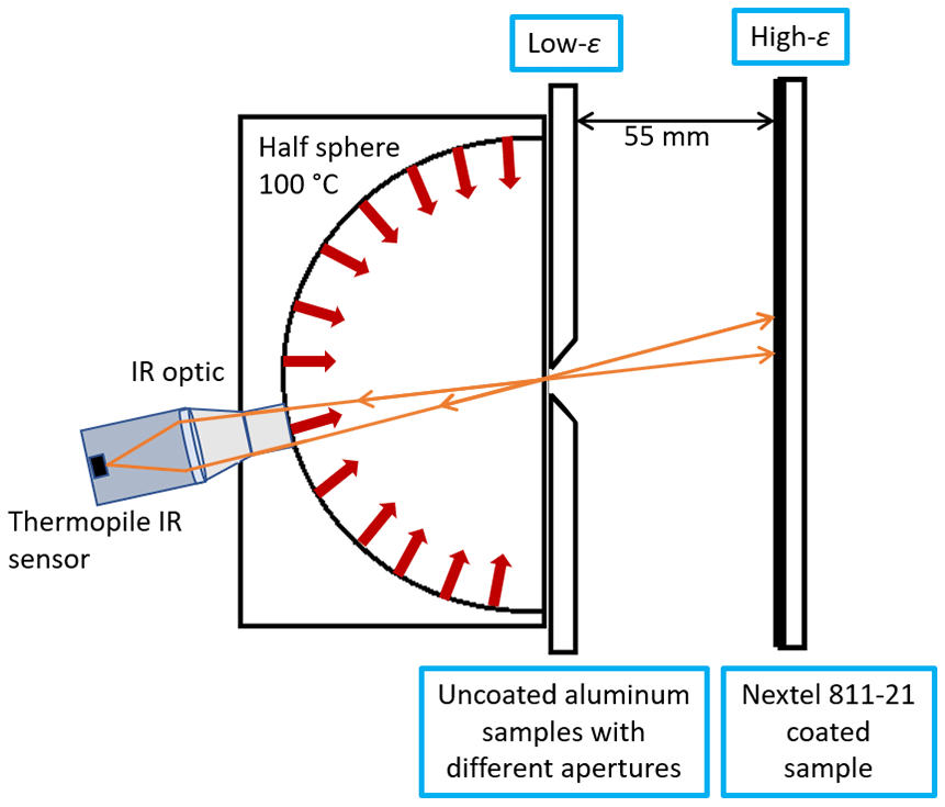
Figure 3Principle of the measurement field size determination of the TIR 100-2 with the varied aperture method. Side view.
3.2 Scanning aperture method
For the sake of comparison with the results of the varied aperture method and to verify the circular shape of the measurement field of the TIR 100-2, we made additional measurements using the scanning aperture method. With this approach, the apparent emissivity while scanning a circular aperture with a fixed diameter of 6 mm in the horizontal and vertical directions was measured. Here, for practical reasons, the aperture was not moved, and the TIR 100-2 was scanned in both directions with the aid of two linear stages with respect to the centered aperture in front of the Nextel-coated plate (Fig. 5).
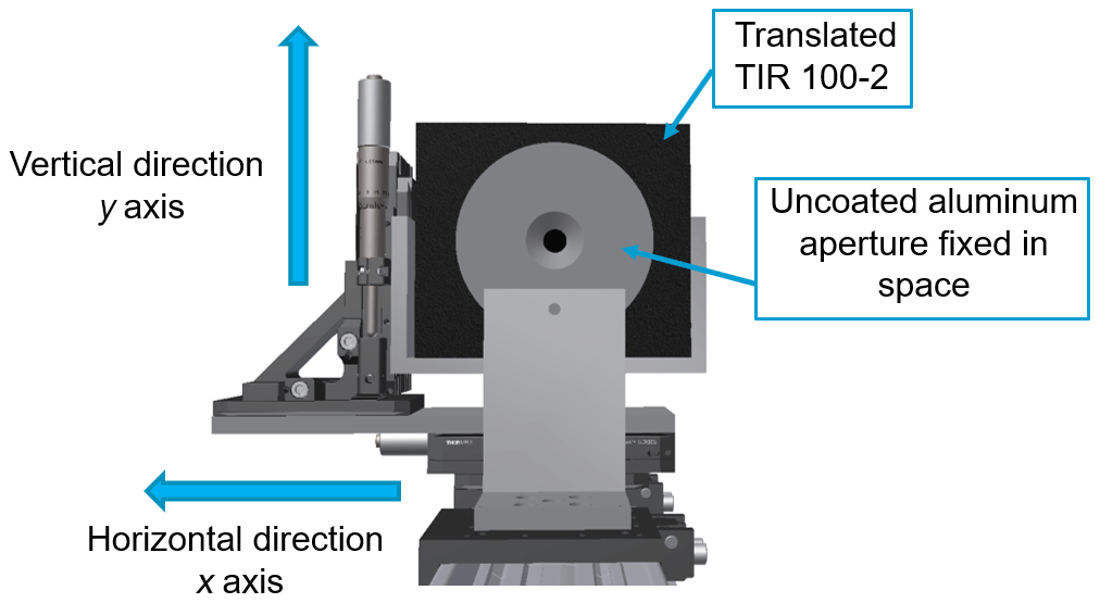
Figure 5Direction of movement of the TIR 100-2 using the scanned aperture method. Front view.
3.3 Results of the measurement field with the varied aperture method
The measurement results of the varied aperture method are shown as dots in Fig. 6. The apparent emissivity indicated by the emissometer shows an increase for larger apertures and an expected saturation for the largest apertures.
The measured data could be fitted by an asymmetrical double sigmoidal function:
where y0 is the offset; A is the amplitude; and are specific parameters of the asymmetrical double sigmoidal function, which were integrated over the aperture area. Due to the cylinder symmetry, the integration was undertaken using Guldins rule, which involved rotating a cross section of the function f(r) in the xy plane around the y axis:
The course of the modeled data is shown in Fig. 6 as a continuous line and follows the measured data very well. This model allows for the determination of the size of the measurement field, for example, as the full-width at half-maximum of the function.
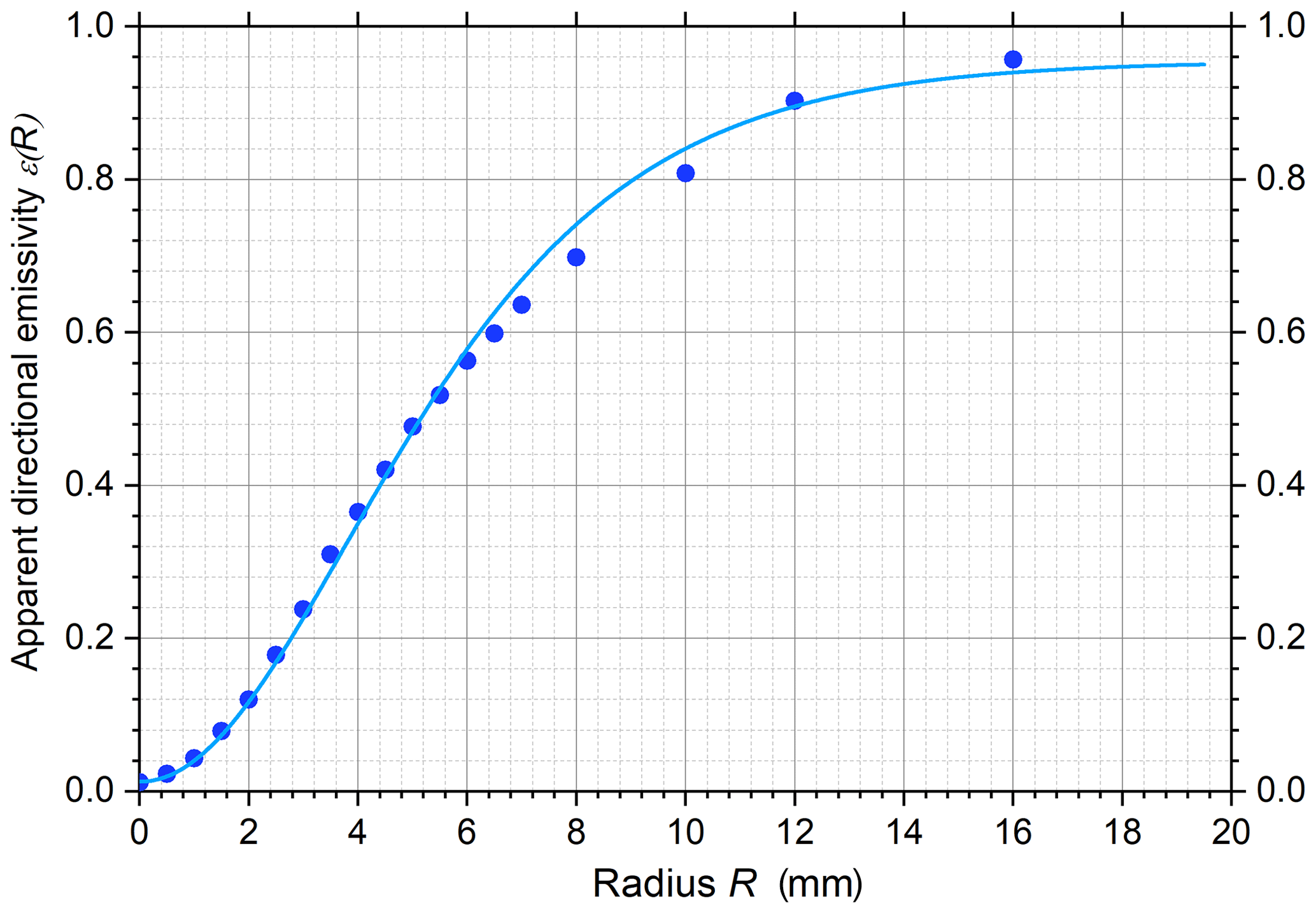
Figure 6Apparent directional emissivity ε(R) measured with the TIR 100-2 for different-sized apertures corresponding to a determination of the measurement field of the instrument. The measured data are compared with a model for the measurement field size function f(R) integrated over the respective aperture sizes according to Eq. (2).
3.4 Results of the measurement field with the scanning aperture method
Using the two linear stages to move the TIR 100-2 with respect to the fixed aperture, we measured the apparent emissivity of the Nextel sample in steps of 500 µm in the horizontal and vertical directions (Fig. 7). The results obtained for both scanning directions are shown as dots in Fig. 7: Fig. 7a for a vertical displacement, and Fig. 7b for a horizontal displacement. Slightly asymmetric shapes and slightly different widths of both curves are obvious.
Consequently, a different approach had to be used to model these results. Here, the measured data were compared with an asymmetric double sigmoidal function f(r) integrated in 2-D along the x and y axes, over a circular area:
with the radius R of the circular aperture being fixed to 3 mm. Equation (3) shows the case for horizontal displacement along the X position. Two slightly different parameterized functions fit the measured results for the horizontal and vertical scanned cases very well. Furthermore, both functions differ from the one used for the varied aperture method. Again, the fitted function allows for the determination of the size of the measurement field for both the horizontal and vertical directions, for example, as the full-width at half-maximum of these functions.
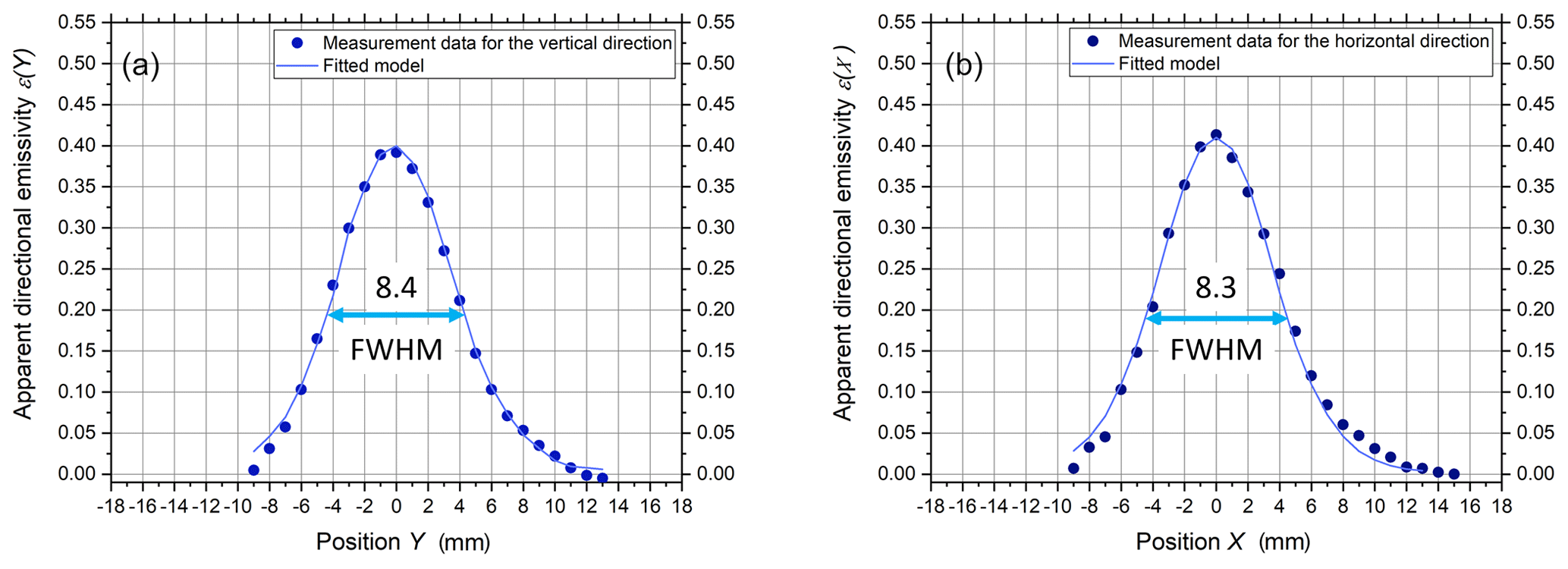
Figure 7(a, b) Measured apparent directional emissivity ε(Y) and ε(X) when scanning a round aperture with a radius R (R=3 mm) over the measurement spot of the TIR 100-2 in the vertical (a) and horizontal (b) directions. The results are compared with a model function integrated over the corresponding area at the respective position Y or X according to Eq. (3). (FWHM refers to the full-width at half-maximum.)
3.5 Comparison of both measurement methods and conclusion
By fitting the model functions to the measurement data, it is possible to analyze the dimensions of the measuring field of the TIR 100-2 using both methods. Figure 8 shows a 3-D illustration of the measurement spot of the TIR 100-2 modeled with Eq. (2) fitting the varied aperture data. This model lacks, of course, the information regarding a possible asymmetry.
The full-width at half-maximum of the asymmetrical double sigmoidal function integrated over round apertures is 8.5 mm. The full-width at half-maximum of the asymmetrical double sigmoidal function integrated in 2-D along the x and y axes is 8.3 mm in the horizontal direction and 8.4 mm in the vertical direction. These values are compared in Table 2 with the values calculated for the area which encloses 90 % of the integrated signal.
Table 2Measurement field of the TIR 100-2 determined with the two different methods.
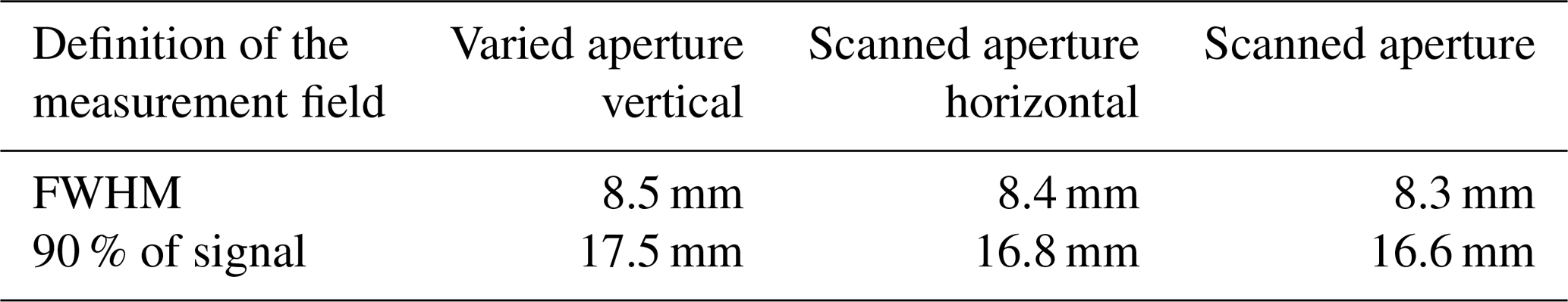
Both measurement methods have their specific advantages. The varied aperture approach is simple and robust and has good signal-to-noise ratios for larger apertures, i.e., when measuring the margins of the measurement field. This is critical with the scanned aperture method, but this approach has the advantage of being able to reveal possible asymmetries of the measurement field. A slight asymmetry could be identified by comparing the two methods. The determined measurement fields of both methods agree within their measurement uncertainties.
A precise and traceable calibration procedure is very important for reliable measurement results. The calibration of the TIR 100-2 is usually carried out using a calibration set of two reference samples which are provided by the manufacturer Inglas and come with the emissometer (Table 3). One sample is a micro-milled aluminum mirror with low emissivity. The other sample is a blackened, ribbed surface with high emissivity. For correct results the temperatures of the reference samples and the measured sample must be equal during the measurement process. Therefore, the reference samples and the measured sample have to be measured as quickly as possible and then be removed from the TIR 100-2 to avoid unnecessary heating. Furthermore, the reference samples should be remeasured at least every 10 min to compensate for a possible thermal drift of the instrument.
Within the EMIRIM project, five additional reference samples were developed and characterized by PTB: a sample that had high specular reflection (a gold mirror with a Y2O3 coating), a sample that had strongly diffuse reflection (Infragold coating), a sample with an emissivity in the medium range (gold coating on a laser-structured surface) and two samples with high emissivity (Aremco coating and Nextel 811-21 coating). The PTB calibration set 1 consisted of a sample that had high specular reflection (a gold mirror with a Y2O3 coating) and a high-emissivity sample (Nextel 811-21 coating). The PTB calibration set 2 consisted of a sample that had high specular reflection (a gold mirror with a Y2O3 coating) and a sample with an emissivity in the medium range (gold coating on a laser-structured surface). The directional total emissivity of all reference samples was measured by the EMAF at PTB (Monte et al., 2010). The emissivities of the reference samples applied in this work are given in Table 3.
Table 3The applied reference samples' directional total emissivity values for the three calibration sets of the TIR 100-2.
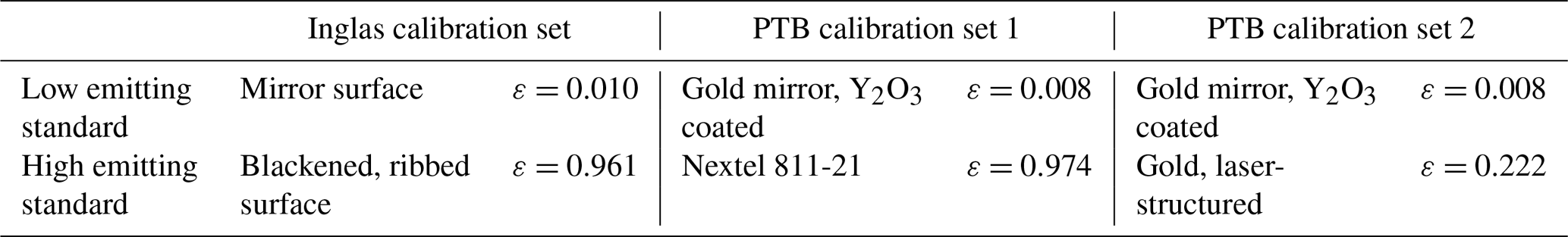
All three calibration sets given in Table 3 were applied to calibrate the TIR 100-2. The normalized and processed sensor signal of the thermopile detector as a function of the emissivity of the reference sample is shown in Fig. 9. With the Inglas calibration set and the PTB calibration set 1 a very low-emissivity and a very high-emissivity reference sample are applied to span almost the complete measurement range of the emissometer. For the PTB calibration set 2, the second calibration point is provided by the gold, laser-structured sample with a directional total emissivity of only 0.222. This choice of a relatively low “highly emissive” reference sample is justified by the intention to measure highly reflective foils with emissivities below 0.2. In this case, placing the calibration points closer to the expected sample emissivity might lead to smaller uncertainties.

Figure 8The measurement field of the TIR 100-2 shown as a 3-D plot resulting from the varied aperture method.
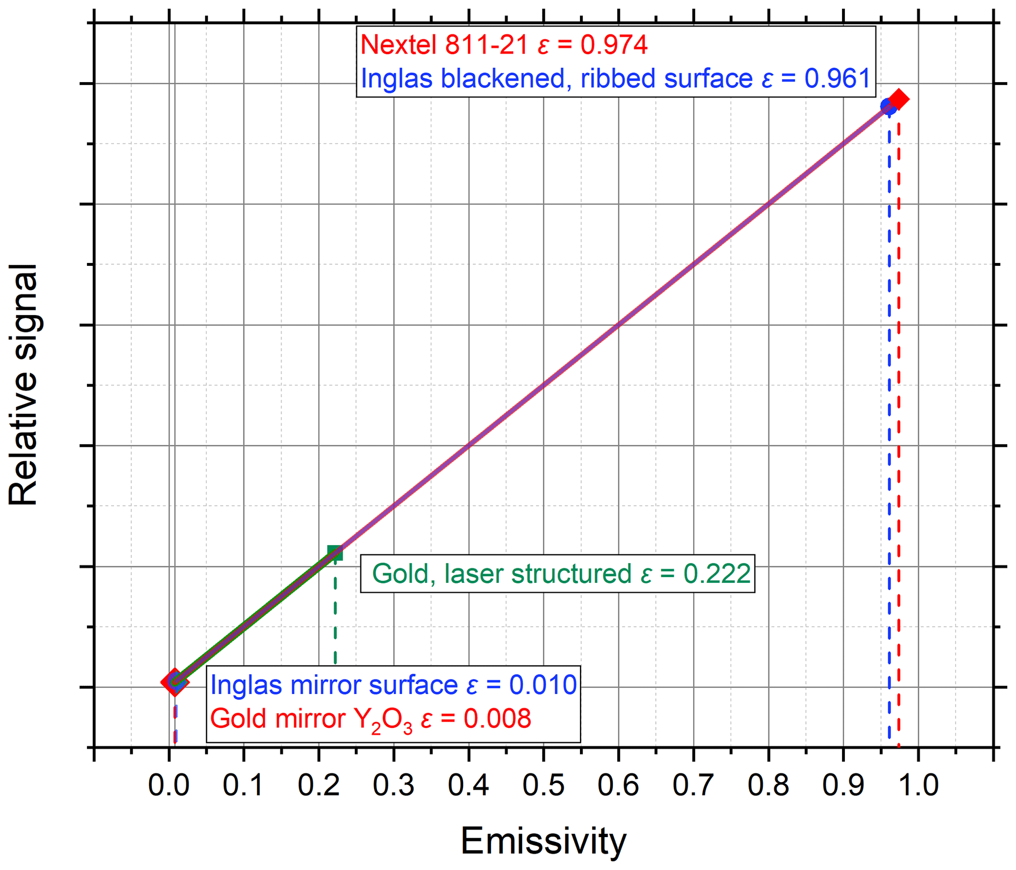
Figure 9The calibration of the TIR 100-2 with the three calibration sets given in Table 3. The dependence of the relative sensor signal on the emissivity of the reference sample is shown.
To validate the performance of the calibrated TIR 100-2, it was utilized for the measurement of the directional total emissivities of four different thermal insulation foils. A bare aluminium foil was commercially provided by the company Eurofoil. The company ACTIS, with support from PTB and the The Laboratoire national de métrologie et d'essais (LNE), produced three more types of foils: polyethylene (PE) foil “colorless lacquered”, PE foil “copper lacquered” and mesh reinforced foil (aluminium color). A photo of each type of foil is shown in Fig. 10. The thicknesses and thermal conductivities of these foils are given in Table 4.
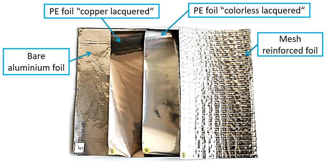
Table 4Thicknesses and thermal conductivities of the four different types of foils selected for emissivity measurement.
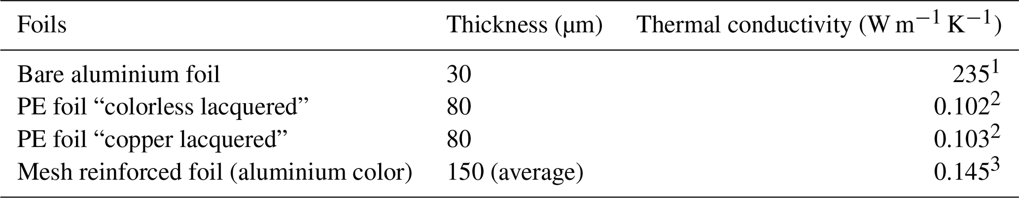
1 Value from literature (European Aluminium Foil Association, 2019). 2 Value measured by PTB, applying a thermal constants analyzer (Hot Disk AB, 2019). 3 Value calculated based on information from the manufacturer (ACTIS Insulation Ltd, 2019.).
First, the directional spectral emissivity of the four selected foils was measured at the emissivity setup of the EMAF at PTB. These measurements were performed in the wavelength range from 5 to 20 µm and at a nominal temperature of 25 ∘C. The EMAF provided emissivity data on these foils with a standard uncertainty from 0.020 to 0.024. Then, for emissivity measurements using the TIR 100-2, two different calibration sets were used. One set of measurements was performed with the TIR 100-2 calibrated using the Inglas calibration set; another set of measurements was performed with the TIR 100-2 applying the PTB calibration set 2, including the plane gold mirror sample (ε=0.008) and the gold, laser-structured sample (ε=0.222). In this case, the emissivity values of the reference samples were closer to the expected emissivity data of the foils.
Table 5 summarizes the emissivity results and measurement uncertainties obtained. The emissivity is given for an angle of observation close to the normal of the observed surface. The achieved uncertainties from the EMAF at PTB are calculated according to the “Guide to the Expression of Uncertainty in Measurement” (GUM; Monte et al., 2010; Adibekyan et al., 2017). For the TIR 100-2, a standard uncertainty of 0.050 is assumed. It should be mentioned here that one of the goals of the EMIRIM project is to provide a detailed uncertainty budget for the TIR 100-2 as part of its complete characterization; with the improved characterization and validation of the instrument, the project aims for a standard uncertainty of 0.030. As the complete characterization of the instrument requires further work, the conservative uncertainty of 0.050 is given here. From Table 5 it is seen that all emissivity results obtained with three different instruments and/or calibrations are consistent within the combined measurement uncertainties. Furthermore, it is seen that the TIR 100-2 systematically measures slightly smaller emissivities than the EMAF. Finally, the results of the TIR 100-2 do not significantly depend on the chosen calibration set. Results obtained using PTB calibration set 2 are only slightly higher than those obtained with the Inglas calibration set.
Table 5The directional total emissivities and standard uncertainties of selected foils measured at the EMAF and using the TIR 100-2 with the two different calibration sets.
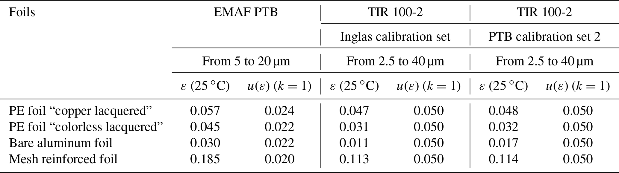
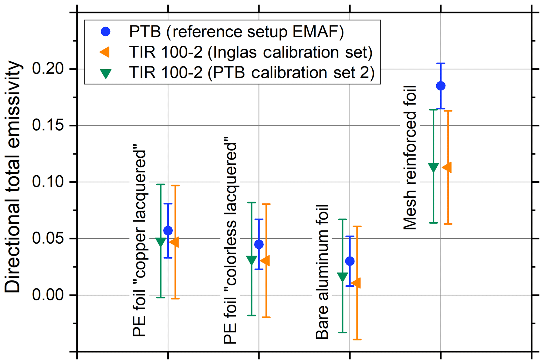
Figure 11Directional total emissivity of selected foils measured by the EMAF at PTB and using the TIR 100-2 with the two different calibration sets.
From the directional total emissivity given in Table 5 the hemispherical total emissivity was determined. In the case of the EMAF measurements, the directional total emissivity was measured under several angles of observation spanning the range from 10 to 70∘ with respect to the sample surface normal. The hemispherical total emissivity is obtained from these data using a theoretical model based on integrating the Fresnel equations in the angular range from 0 to 90∘ (Monte et al., 2010; Adibekyan et al., 2017). The TIR 100-2 is an instrument that only measures the directional total emissivity under an angle of observation close to the perpendicular of the surface. If the hemispherical emissivity of the four foils is calculated from the TIR 100-2 data in Table 5, a conversion factor has to be used. The European standards EN 673 and EN 12898 (German standard DIN 12898: 2001-04, 2001; DIN EN 673:2011-04, 2011) list a table of correction factors which can be applied for flat metal surfaces and foils. Intermediate values can be obtained by linear interpolation or extrapolation with sufficient accuracy from this list. The application of the correction factor for mesh reinforced foils might be not applicable and is shown here for illustration purposes only. The directional and hemispherical emissivity data measured by the EMAF at PTB and data measured using the TIR 100-2 are presented in Table 6. The directional total emissivity values from the TIR 100-2 were obtained with the help of the Inglas calibration standards. The conversion factors to calculate the hemispherical total emissivity were taken from EN 12898. The uncertainty of the conversion factors was assumed to be zero. From Table 6 it is seen that all hemispherical total emissivity results determined by the EMAF and the TIR 100-2 are consistent within the combined measurement uncertainties. However, the hemispherical total emissivities determined from the TIR 100-2 measurements and the conversion factors of EN 12898 are systematically lower than the results obtained by the EMAF: they are always outside the confidence intervals of the EMAF but are still consistent, as the TIR 100-2 results have an assumed uncertainty of 0.05.
Table 6The data of the measured directional total emissivity and the calculated hemispherical total emissivity of the foils performed by the EMAF at PTB in the wavelength range from 5 to 20 µm and the TIR 100-2 in the wavelength range from 2.5 to 40 µm.
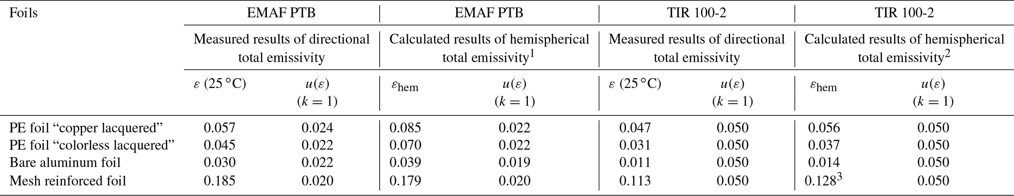
1 Integration of the Fresnel model (Monte et al., 2010; Adibekyan et al., 2017). 2 EN 673 and EN 12898 (German standard DIN 12898: 2001-04, 2001; DIN EN 673:2011-04, 2011). 3 Not applicable, see text.
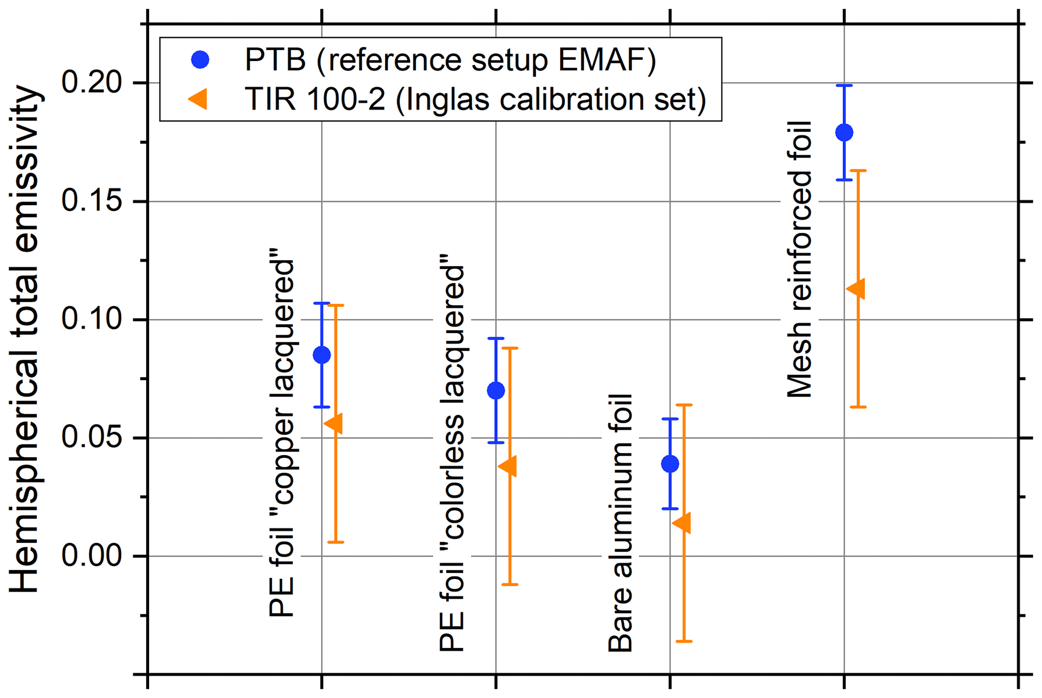
Figure 12Hemispherical total emissivities of selected foils measured by the EMAF at PTB and by the TIR 100-2 according to EN 12898.
To further validate the performance of the calibrated TIR 100-2 it was utilized for the measurement of the directional total emissivities of four different high-emissivity black coatings. The emissivities of several frequently used black coatings, namely Nextel 811-21, Herberts 1534, Acktar Ultra Black and Acktar Fractal Black, were extensively investigated at PTB with very low uncertainties in a broad temperature and wavelength range and were published in Adibekyan et al. (2017). To evaluate the capabilities of the TIR 100-2 in the case of high-emissivity surfaces, these black coatings were measured by applying two different calibration sets: the Inglas calibration set and the PTB calibration set 1, with a gold mirror with Y2O3 coating and the Nextel 811-21 sample. Again, it is necessary to note the slightly different wavelength ranges: directional total emissivity values at EMAF were obtained by integrating over the range from 5 to 20 µm, whereas the TIR 100-2 values were measured between 2.5 and 40 µm.
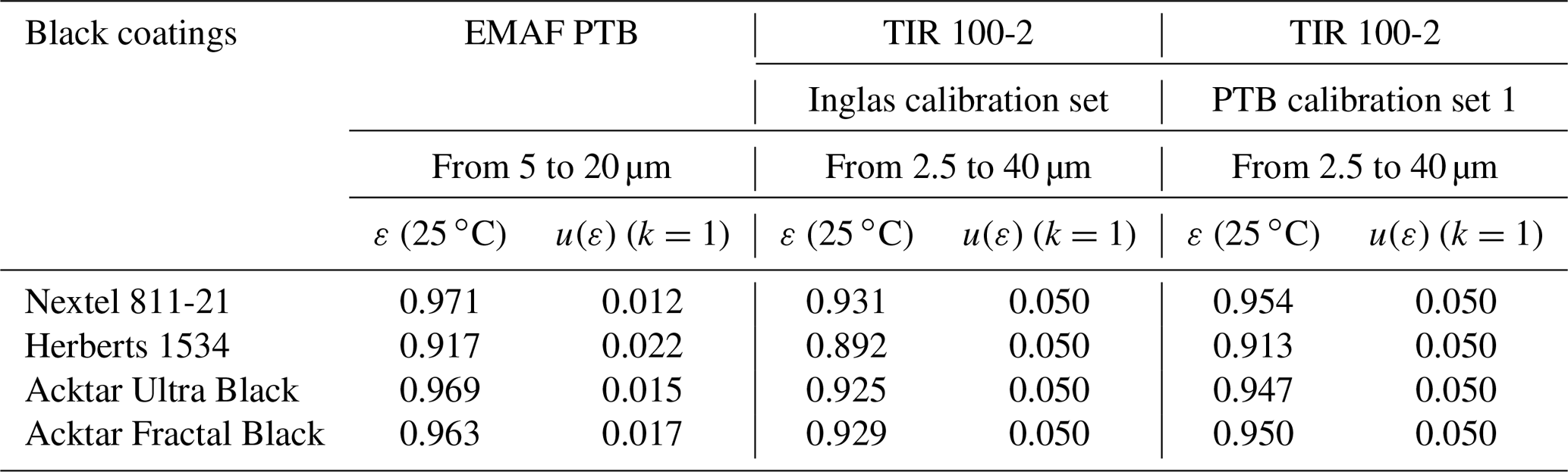
Table 7 summarizes the emissivity results and measurement uncertainties obtained. The emissivity is given for an angle of observation close to the perpendicular of the observed surface. The achieved uncertainties from the EMAF at PTB are calculated according to the GUM (Monte et al., 2010; Adibekyan et al., 2017). All results obtained with the TIR 100-2 agree well with the measurements performed by the EMAF at PTB within the combined uncertainties. However, a significant improvement of the results is clearly noticeable for all four black coatings when using the PTB calibration set 1.
Table 7The directional total emissivities and standard uncertainties of the four black coatings measured at the EMAF and measured using the TIR 100-2 with the two different calibration sets.
The directional total emissivity of the four black coatings measured by the EMAF at PTB and using the TIR 100-2 with two different calibration sets is shown in Fig. 13.
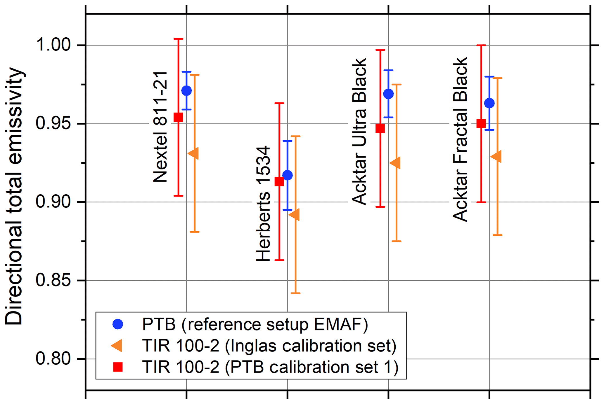
Figure 13Directional total emissivity of the four black coatings measured by the EMAF at PTB and measured using the TIR 100-2 with the two different calibration sets.
The diameter of the measurement field of the TIR 100-2 was determined at PTB by applying two different methods: the varied aperture method and the scanning aperture method. The mathematical models of these methods allow for the determination of the size of the measuring field as the full-width at half-maximum of the fitted function. The size of the measurement field of the TIR 100-2 determined using the varied aperture method was 8.5 mm. With the scanned aperture method the measurement field size was equal to 8.4 and 8.3 mm for the vertical and horizontal directions, respectively. Thus, a slight asymmetry of the measurement field of the TIR 100-2 could be identified, and the size of the measuring spot obtained using two different methods was consistent.
The calibration accuracy of the TIR 100-2 was investigated by applying reference samples from three different calibration sets. Along with the calibration set provided by Inglas, the reference samples developed within the EMIRIM project and characterized at PTB with very high accuracy were used: the PTB calibration set 1 included the Nextel 811-21 (ε=0.974) and the gold mirror, Y2O3-coated (ε=0.008)reference samples; and the PTB calibration set 2 included the gold laser-structured sample (ε=0.222) and the gold mirror, Y2O3-coated (ε=0.008) reference samples. The TIR 100-2 was utilized for measurements of the directional and hemispherical total emissivities of thermal insulation foils and the highly emissive coatings. The results achieved were validated by comparing them with measurements performed by the EMAF at PTB. The uncertainties of the EMAF measurements are calculated according to the GUM (Monte et al., 2010; Adibekyan et al., 2017). For the TIR 100-2, the assumed uncertainty was used to assess consistency.
In summary, the results obtained with the TIR 100-2 for the thermal insulation foils as well as for the black coatings agree well within the combined measurement uncertainties with the exception of the mesh reinforced foil. Furthermore, it is seen that the TIR 100-2 systematically measures slightly smaller emissivities than the EMAF. Applying the newly developed reference samples (calibration set 2) does not significantly change the measurement results for low-emissivity insulation foils. For high-emissivity black coatings, the measured results were notably improved using the new reference samples characterized at PTB (calibration set 1). Thus, the accurately measured emissivity values of the PTB reference samples as well as the application of different calibration sets, which allowed for the selection of the reference samples in such a way that the calibration points were close to the expected emissivity of the investigated sample, led to more accurate measurements with commercially used emissometers such as the TIR 100-2.
Note: the component producers/suppliers are mentioned for identification purposes only. This identification does not imply recommendation or endorsement by the PTB, nor does it imply that the producer/supplier identified is the best available for the purpose.
All relevant measurement results are shown in the publication. However, the underlying measurement data are not publicly available and can be requested from the authors, if required.
EK, AA and CM designed the experiment. EK and CM developed the evaluation procedure. EK performed all measurements and the complete evaluation with support from AA and CM. EK wrote the paper with contributions from JH, AA and CM.
The authors declare that they have no conflict of interest.
This work was performed within the 16NRM06 EMIRIM project that has received funding from the EMPIR programme; EMPIR is co-financed by the participating states and the European Union's Horizon 2020 research and innovation programme.
This paper was edited by Gerald Gerlach and reviewed by two anonymous referees.
ACTIS Insulation Ltd.: available at: https://www.insulation-actis.com/, last access: 19 June 2019.
Adibekyan A., Kononogova E., Monte C., and Hollandt J.: High-accuracy emissivity data on the coatings Nextel 811-21, Herberts 1534, Aeroglaze Z306 and Acktar Fractal Black, Int. J. Thermophys., 38, 89, https://doi.org/10.1007/s10765-017-2212-z, 2017.
Albaticia R., Passerinia F., Tonellib A. M., and Gialanellac S.: Assessment of the thermal emissivity value of building materials using an infrared thermovision technique emissometer, Energ. Buildings, 66, 33–40, doi.org/10.1016/j.enbuild.2013.07.004, 2013.
CEN/TC 89/WG 12 N 209: Note of internal communications between members of working group CEN/TC 89/WG 12, 2013.
Directive 2010/31/EU: Directive 2010/31/EU of the European Parliament and of the Council on the energy performance of buildings, available at: https://eur-lex.europa.eu/LexUriServ/LexUriServ.do?uri=OJ:L:2010:153:0013:0035:EN:PDF (last access: 19 June 2019), 2010.
European Aluminium Foil Association (EAFA): available at: https://www.alufoil.org/en/home.html, last access: 19 June 2019.
Expression by the standardisation group CEN/TC 89/WG 12: The need for improvement of total hemispherical emissivity of low emissivity foils used in reflective insulation products, available at: https://www.giordano.it/uploaded-files/primo piano/16NRM06_Publishable_Summary.pdf (last access: 19 June 2019), 2017.
German standard DIN EN 12898: 2001-04: Glass in building, Determination of the emissivity, 2001.
German standard DIN EN 673:2011-04: Glass in building, Determination of thermal transmittance (U value) – Calculation method, 2011.
Hervea P., Cedellea J., and Negreanub I.: Infrared technique for simultaneous determination of temperature and emissivity, Infrared Phys. Techn., 55, 1–10, doi.org/10.1016/j.infrared.2010.09.001, 2012.
Hot Disk AB: The Hot Disk DPS 2500, available at: https://www.hotdiskinstruments.com/, last access: 19 June 2019.
INGLAS Produktions GmbH: TIR 100-2. Thermal Emissivities measured within seconds, available at: https://www.tir100.de/, last access: 19 June 2019.
JRP EMIRIM: Improvement of emissivity measurements on reflective insulation materials, available at: http://projects.lne.eu/jrp-emirim/ (last access: 19 June 2019), 2017.
Monte C. and Hollandt J.: The determination of the uncertainties of spectral emissivity measurements in air at the PTB, Int. J. Metrologia, 47, 172–181, https://doi.org/10.1088/0026-1394/47/2/S14, 2010.
van der Ham E. W. M. and Ballico M. J.: Handheld Reflective Foil Emissometer with 0.007 Absolute Accuracy at 0.05, Int. J. Thermophys., 35, 1310–1319, https://doi.org/10.1007/S10765-014-1639-8, 2014.
- Abstract
- Introduction
- Measuring principle of the TIR 100-2
- Characterization of the measurement field of the TIR 100-2
- Calibration of the TIR 100-2
- Emissivity measurements on thermal insulation foils
- Emissivity measurements on high-emissivity coatings
- Conclusions
- Data availability
- Author contributions
- Competing interests
- Financial support
- Review statement
- References