the Creative Commons Attribution 4.0 License.
the Creative Commons Attribution 4.0 License.
Cylinder pressure sensors for smart combustion control
Dennis Vollberg
Dennis Wachter
Thomas Kuberczyk
Günter Schultes
Different sensor concepts for time-resolved cylinder pressure monitoring of combustion engines are realized and evaluated in this paper. We distinguish a non-intrusive form of measurement outside the cylinder, performed by means of a force compression rod from intrusive, real in-cylinder measurement by means of pressure membrane sensors being exposed to the hot combustion process. The force compression rod has the shape of a sine wave with thinner zones equipped with highly sensitive foil strain gauges that experience a relatively moderate temperature level of 120 ∘C. The sensor rod delivers a relative pressure value that may be influenced by neighbour cylinders due to mechanical coupling. For the intrusive sensor type, two different materials for the membrane-type sensor element were simulated and tested, one based on the ceramic zirconia and the other based on stainless steel. Due to the higher thermal conductivity of steel, the element experiences only 200 ∘C while the zirconia element reaches 300 ∘C. Metallic chromium thin films with high strain sensitivity (gauge factor of 15) and high-temperature capability were deposited on the membranes and subsequently structured to a Wheatstone bridge. The pressure evolution can be measured with both types in full detail, comparable to the signals of test bench cylinder pressure sensors. For the preferential steel-based sensor type, a reliable laser-welded electrical connection between the thin films on the membrane and a copper wire was developed. The in-cylinder pressure sensors were tested both on a diesel test bench and on a gas-fired engine. On the latter, an endurance test with 20 million cycles was passed. Reliable cylinder pressure sensors with a minimum of internal components are thus provided. The signals will be processed inside the sensor housing to provide analysis and aggregated data, i.e. mass fraction burned (MFB50) and other parameters as an output to allow for smart combustion control.
- Article
(5432 KB) - Full-text XML
- BibTeX
- EndNote
Although the issue of accurate pressure sensing in cylinders of combustion engines was tackled decades ago, the technology is not widespread in today's mass-produced passenger cars and other combustion engines. Many advantages of real-time controlled combustion processes, based on time-resolved pressure data in each cylinder, were described in an early review article by Powell (1993). Time-resolved pressure measurements represent the most fundamental source of information on the evolution of each combustion, because it is far more direct compared to other signal sources originating from knock sensors, cam shaft sensors, mass air flow (MAF) sensors or manifold absolute pressure (MAP) sensors to mention only a few sensor types being integrated in today's engines. Probably only a fraction of research results on cylinder pressure sensors and their interplay with other sensor signals appear in the literature due to the competitive situation of the car industry. As powerful real-time data processing is associated with minimal costs, further efforts in the sensory part should be made to reach lower fuel consumption and minimize pollution.
Of course, the requirements for reliable pressure transducers in the harsh environment of the engine are challenging. The sensors must be cost-effective and very production-viable, they have to work reliably for up to 109 cycles during the lifetime of a car, and they have to meet the installation and packaging requirements of modern engines. The requirements are certainly different if the focus is put on test bench operations. Pressure sensors for this purpose (Kistler, 2018) are used extensively during the development of new engines and they often serve as reference sensors in studies.
The first cylinder pressure sensors were of non-intrusive type and could be applied by simply replacing the washer of a spark plug (Kondo et al., 1975; Sellnau et al., 1993, 2000). Basically, this ingenious design consists of a piezoelectric ring that is elastically compressed by a fraction of the force developed by the combustion pressure. These sensors represent an indirect pressure detection and provide a relative measure but not an absolute measure of pressure. This will suffice for a closed-loop combustion control if changes of sensitivity and bias are permitted in a certain range (Schiefer et al., 2003). Such non-intrusive sensors can either be combined with or integrated into existing devices like glow plugs, spark plugs or injection valves (Simon and Krebs, 1999), or they can be designed as stand-alone sensors. In principal, no access bore into the cylinder is needed, for the sensor has only to be installed in a structural load path. Of importance is the moderate temperature level of < 150 ∘C for non-intrusive sensors because they can be mounted outside the cylinder onto cooled engine parts.
Sensors for direct or intrusive pressure measurement are designed differently. Direct access to the combustion chamber is needed, allowing a measurement of the physical pressure, which the force of the compressed and combusting fuel gas mixture on a defined area inside the cylinder. A major difficulty is the higher temperature level of these in-cylinder sensor heads. Depending on the design, materials, and the thermal coupling to cooled engine parts, the temperature can reach more than 200 ∘C. Intrusive pressure sensors are usually calibrated during the production process in order to provide a signal representing the absolute pressure value. Again, as in the former case, intrusive sensors can either be combined or integrated into a glow plug or spark plug or work as pressure-only sensors, with access to the cylinder provided by an additional bore. The temperature level is often reduced by a thermally decoupling tip transferring the force onto the backward-arranged sensing element (Hidria, 2018).
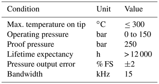
For the transformation of force or pressure into the respective electrical value, different physical effects can be applied, namely piezoelectricity (Sellnau et al., 2000; Hellemanns et al., 2011; Hidria, 2018; Ura and Oya, 2018), optical fiber-based reflection of a membrane (Ulrich et al., 2001), ion-current measurements (Saitzkoff et al., 1997), magnetostriction (Gustafsson et al., 1998), piezoresistivity with silicon strain gauges (Sensata, 2015), and pressure sensors based on thin film strain gauges (Last et al., 2009), a version also used in our work. Typical requirements for cylinder pressure measurements are summarized in Table 1.
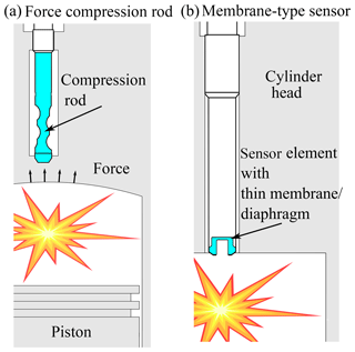
In consideration of the fact that cylinder pressure sensors are not applied by default in modern passenger cars and the perception that existing sensors are often constructed elaborately with a lot of different assembly parts, we engineered different constructions. The basis of our work presented in this paper stems from the research on new materials, especially temperature-stable thin films that transform strain into a resistance change very effectively, allowing higher sensitivity and higher operating temperatures. In order to compare the above-mentioned different approaches we designed a non-intrusive force compression rod equipped with highly sensitive foil strain gauges and two versions of an intrusive pressure sensor with different membrane materials and highly sensitive thin films. In this context, the term membrane means a diaphragm with inherent stiffness being clamped on the edge. A deformable plate is another term for membrane, but we will use the terms membrane or diaphragm throughout this text. The principal difference of the sensor types is depicted in Fig. 1. The signal processing in the sensor housing and the algorithms to extract and supply key information like the mass fraction burned (MFB50) and the indicated mean effective pressure (pmi) directly as a sensor signal, allows smart combustion control. This data processing and the rapid prototype engine control unit will be presented in a forthcoming paper.
All sensor concepts are designed with respect to the geometrical dimensions and the requirements of an existing test bench with a diesel engine (1.6 L TDI, 66 kW, VW). The diesel works as a compression-ignition engine and therefore the sensors can be mounted in the glow plug bore of one cylinder without any engine modification. As a reference, a glow plug pressure sensor (PSG type, accuracy ±2 % FS, Beru) was mounted in a second cylinder, allowing a comparison of pressure profiles of nearly identical combustion cycles. Our sensor prototypes were tested at various engine speeds (1800–3600 rpm) and torque values (0–200 Nm).
For long-term runs, a test bench with a gasoline engine (air-cooled V-Twin, 479 cc, 11.8 kW, Briggs & Stratton) was used. This engine is powered with natural gas and runs at a constant speed of 2600 rpm for more than 250 h to realize over 20 million load cycles. The gasoline engine has two cylinders arranged at an angle of 90∘ to each other, allowing an easier access compared to the diesel engine. One of the cylinder heads was modified with two additional bores to host two prototype sensors and one reference sensor, built in a measuring spark plug (type 6118, accuracy ±1 % FS, Kistler). Hence, the pressure evolution in the same cylinder could be measured simultaneously with three pressure sensors.
In addition, a static pressure test bench to characterize sensitivity, linearity, hysteresis, and drift of the prototype sensors was installed, especially for the membrane-type sensors. Gas pressure was controlled by a high-precision pressure controller (CPC 8000, accuracy ±0.01 % FS, Wika), allowing calibration and tests up to 300 bar at temperatures up to 300 ∘C. The force compression rod, on the other hand, may not be tested on the static pressure test bench, because its sensitivity strongly depends on the mounting location and the surrounding mechanical stiffness of the engine.
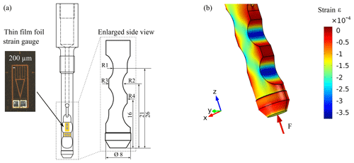
Figure 2(a) Schematic drawing of the compression rod. The enlarged side view shows the resistances R1 to R4, which are connected to a Wheatstone bridge measuring the compression rod's deformation. All dimensions in millimetres. (b) Structural FE analysis of the force compression rod.
2.1 Non-intrusive force compression rod
We start with a non-intrusive design of a force compression rod with indirect mechanical access to the combustion chamber (see Fig. 1a). The robust and massive rod-like sensor geometry will be compressed by the cylinder head deformation caused by pressure evolution in the cylinder. Highly sensitive foil strain gauges (Vollberg et al., 2015) are placed on the rod at a distance of approx. 2 cm from the combustion chamber to reduce the temperature level. By means of structural finite-element (FE) analysis performed with COMSOL Multiphysics, we evaluate suitable shapes of the rod for the application of strain gauges. As material the stainless steel PH 13-8 Mo (1.4534) was selected, being a high-strength alloy with a Young modulus of 210 GPa, known as a good steel for force transducers and excellent temperature-stable mechanical properties. By variation in different designs of the rod's front end (e.g. reducing the diameter, introduction of a stud hole), the best geometry we found is a sine-wave-like form with a phase shift of 180∘ for two opposite sides, depicted in Fig. 2a. The maximum diameter is 8 mm and the thinnest part is approx. 3.9 mm. Upon a force F equivalent to a pressure of 250 bar, applied on the tip of the rod, the geometry develops a negative strain of −0.34 ‰ (blue zones in Fig. 2b) and a mechanical stress of σ≈610 MPa on the surface of the contour (positions at R1, R2 in Fig. 2a). Additionally, there are areas with almost no strain (positions at R3, R4 in Fig. 2a and red zones in Fig. 2b). By having locations with compression and others without deformation, the geometry is suitable for foil strain gauge application. To take advantage of highly sensitive foil strain gauges, applied onto zones as illustrated in Fig. 2a, a very robust design of the rod was possible, attaining a compressive strain of only a third compared to typical strain gauge applications.
The thin film sensor materials are described elsewhere (Vollberg et al., 2015; Schultes et al., 2018; Schwebke et al., 2018). In brief, the backing material of the strain gauges is a 50 µm thick polyimide (PI) foil to ensure a good electrical insulation to the steel. The PI foil is coated with a highly strain-sensitive thin film in a combined plasma-enhanced vapour deposition process (PECVD). The thin film with a thickness of approx. 100 nm consists of metal clusters and columns of NiCr embedded in a graphite-like carbon matrix. The strain sensitivity (gauge factor) of such a sensor film is enhanced by a factor of approx. 5 compared to commercially available metal foil strain gauges. Simultaneously the temperature dependency is low. The sensor layer is structured by an ultrashort pulsed UV-laser system that allows the film to be removed by cold ablation without damaging the PI foil underneath (Langosch et al., 2015). To ensure electrical connection an additional multilayer thin film (NiCr/Ni/Au) is partially sputtered onto the designated contact pad areas. In a final step a covering PI foil is laminated over the strain gauges to prevent damaging. As a result of the FE analysis the active area of the strain gauge should be 1.3 mm2. With a structure path width of 200 µm and a separation of 30 µm between the conductive lines, we designed six parallel paths with a total resistance of approx. 5 kΩ. This is a good compromise between power consumption of the bridge and electrical noise. The thin film strain gauges are glued just as well-known commercial gauges are, with hot curing epoxide resin (M-Bond 610, Vishay) on the intended areas. After curing, the strain gauges were wire connected by soldering with a high-temperature solder (Solder HMP, P/N 610128, BLH).
Table 2Material properties of the membrane-type sensor elements.
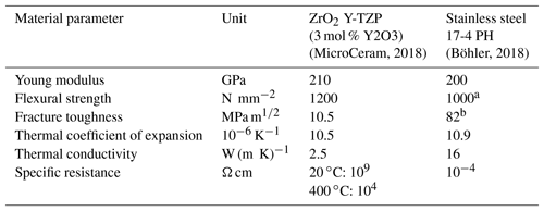
a Corresponds to 0.2 % proof stress in hardened state. b Farahmand and Nikbin (2008).
2.2 Intrusive membrane-type sensors
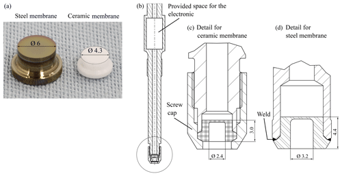
An intrusive sensor design was developed as well. The concept uses membrane elements (Fig. 3a), mounted at the front end of a tube-like structure with direct access to the pressure inside the cylinder. The measuring elements either consist of a ceramic material based on zirconia or stainless steel with the relevant parameters summarized in Table 2. Both materials offer good mechanical properties at elevated temperatures and hence enable direct in-cylinder pressure measurement. To acquire information about the effective temperature level on the membranes, we first designed temperature-sensitive thin film resistors on the respective elements. Operating the combustion engine at different power levels, we thus were capable of measuring both the maximum temperature and the temperature gradient across the membranes. These results were also useful to conduct and verify the thermal–structural FE analysis, presented in Sect. 3.1.
2.2.1 Ceramic membrane
Figure 3b, c shows a hat-like sensor element with a membrane, clamped by a screw cap at the front end of the sensor housing. The very small sensor element with a membrane diameter of 2.4 mm was designed and simulated by the authors and produced by the company MicroCeram. As material, the ceramic ZrO2 (stabilized with 3 mol % Y2O3) was chosen, because of the very good mechanical parameters and the superior flexural strength of zirconia, compared to other ceramic materials. A larger version of the zirconia-based pressure sensor is described in detail in another paper (Schultes et al., 2015).
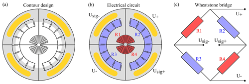
Figure 4(a) Contour design of the Wheatstone bridge for the laser-based patterning. The bright inner zone represents the 300 µm thick membrane and the yellow areas highlight the solder pads, consisting of the multilayer thin film. (b, c) The electrical circuit (Wheatstone bridge) is generated by laser cutting the sensor layer along the black lines (blue areas: resistors R2, R3 measuring negative strain; red areas: resistors R1, R4 measuring positive strain).
First, the geometry was FE-simulated by applying 250 bar. Allowing a maximum mechanical stress of 200 MPa, the membrane has to have a thickness of 300 µm with a given diameter of 2.4 mm. The membrane centre experiences a total displacement of 1.5 µm, thereby developing a maximum strain of 0.64 ‰ (radial and tangential) and a maximum compression with a negative strain of −0.27 ‰ (only radial) at the edge of the membrane. Therefore, the strain measuring gauges R1 and R4 in Fig. 4 are arranged tangentially, while R2 and R3 are oriented in radial direction. The electrically non-conductive ceramic membrane is directly coated with a piezoresistive, chromium-containing thin film and no additional insulation layer is required. The thin film has a gauge factor of about 15 and a film thickness of 60 nm, to be described in a forthcoming paper (Schwebke and Schultes, 2019). Film structuring of a Wheatstone bridge is performed again by laser ablation. For the electrical connection by soldering, the same multilayer thin film described for the foil strain gauges was deposited on the outer parts of the membrane.
2.2.2 Steel membrane
In addition to the ceramic membrane, we investigated a similar version equipped with a sensor element made of stainless steel (17-4 PH, 1.4542) as shown in Fig. 3d. In this case the sensor element is laser-welded to the sensor tube. At first, the membrane was equipped with a 5 µm thick SiO2 insulation layer to ensure good electrical insulation. Owing to different geometric dimensions (i.e. membrane thickness of 260 µm and a diameter of 3.2 mm), the membrane deflects by 4.9 µm while experiencing a von Mises stress of 360 MPa upon a pressure of 250 bar. The centre strain is 1.3 ‰ and the radial compression at the rim is −0.8 ‰, leading to a higher output signal compared to the ceramic version. As well, the thin film application and layout was adapted to the geometry of the steel membrane.
For a reliable operation, secure electrical connections and packaging are of utmost importance. Hence, we strive to establish a more thermally resistant technique than soldering. A laser welding process of a copper wire onto the thin film contact pads was realized by means of a semi-automatic laser system (Lasercab-D 160, wavelength: 1070 nm, max. pulse energy: 15 J, OR-Laser). At first, the tip of a 150 µm copper wire is melted by laser radiation to attain a spherical shape. Subsequently the sphere is melted again onto a contact pad of the sensor element. This two-step process allows contact to be made with the thin film without destroying the insulation layer underneath. The electrical contacts have an electrical conductivity of few milliohms and a mechanical stability in the range of the wire's tensile strength of around 5 N. An example of the electrical connections is depicted in Fig. 5.
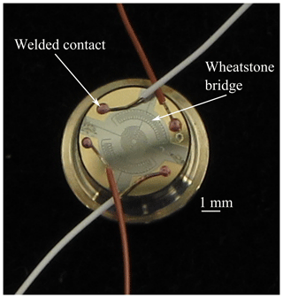
Figure 5Laser-welded Cu wires ensure the electrical contacts to the Wheatstone bridge on the steel membrane.
The Ni-Cu phase diagram (Smithells, 2013) of Ni, being the dominant thin film element, and Cu (wire) shows a complete solubility for both constituents. Such systems are called isomorphous and crystallize as solid solutions without any intermetallic phases. Therefore, this binary metallic system allows for a good weldability.
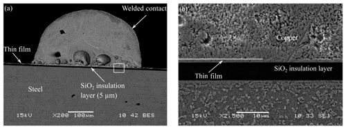
Figure 6(a) SEM image of a cross section of a welded contact. (b) Enlarged detail of the marked rectangular zone at the interface between the thin film and the welded copper contact.
For further investigations a cross section of a welded contact was prepared, polished and chemically etched for an examination with a scanning electron microscope (SEM). The images of Fig. 6 reveal no significant defects between the thin film and the welded copper wire. Remarkably and very importantly, the 5 µm thick SiO2 insulation layer is not damaged, in accordance with the well-preserved high electrical insulation resistance of > 5×10⁹Ω between the steel and the wire. The homogenous alloy of the weld at the interface provides a low-contact resistance as well as a good mechanically stable connection.
3.1 Thermal analysis of the different sensor concepts
To determine the temperature level of the different concepts, prototypes were equipped with temperature sensors and mounted in the diesel test bench, while operating the engine at maximum power (3600 rpm at 200 Nm torque). For the non-intrusive force compression rod, a temperature of approx. 120 ∘C was measured by means of a PT1000 sensor. This result is coherent with the mentioned arguments, as the sensor element is placed 2 cm from the combustion chamber and excessive heat is effectively dissipated to cooled engine parts.
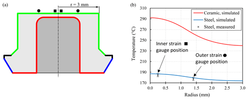
Figure 7(a) Thermal boundary conditions of the membrane. Red: time-dependent heat flux from the combustion, green: thermal convection to air (air temp. 120 ∘C), black: weld to sensor housing (150 ∘C), blue: contact to cylinder head (180 ∘C). (b) Simulated temperature profile over the membrane's top side for steel and ceramic. In addition, the measured temperatures at the appropriate strain gauge positions are included.
The temperature level of the intrusive membrane-type pressure sensors depends on the applied materials – mainly on their thermal conductivity. With the small zirconia element, a temperature of about 295±5 ∘C was measured by means of a thin film resistor integrating the temperature across the membrane. The temperature varies with the engine coolant temperature in a range of ±5 K. The inner-cyclic variation during one combustion cycle is less than 1 K, due to the averaging measuring structure and the slow temperature response behaviour of the ceramic's low heat conduction. To simulate the temperature conditions for the intrusive membranes, the measured data were used to establish a thermal FE model, considering the specific geometries. As boundary conditions, the surfaces of the ceramic element were kept on assumed temperature levels as depicted in Fig. 7a. A periodic heat intake onto the element was simulated as a pulse of triangle shape with maximum heat flux derived from Parra (Parra, 2018) and a pulse width corresponding to a pressure curve at 3600 rpm (heat flux at maximum: 1 MW m−2, pulse width: 3 ms, repetition time: 33.33 ms). The pulse form was adjusted by a scaling factor of 0.75 and the cylinder head temperature was put to 180 ∘C to match the simulation output to the measured temperature of 295 ∘C on the ceramic membrane.
Besides the average temperature level of the membrane surface, the temperature gradient on the membrane is also important for the pressure sensor function. As the heat energy strikes the membrane, the material will absorb and conduct the heat. Obviously the predominant dissipation occurs at the circumferential contact surfaces (blue and black zones of Fig. 7a) into the clamped or welded housing. Consequentially, the membrane centre attains a higher temperature than the periphery. As the resistors of the Wheatstone bridge are arranged at the centre as well as in the periphery of the membrane, a signal would be generated depending on the temperature gradient and the films temperature coefficient (TCR). This signal would represent a distortion of the pressure signal.
The simulation of the zirconia membrane element yielded a temperature gradient of approx. 30 K from the inner gauge position at a radius of 0.25 mm to the outer strain gauge position at a radius of 1.4 mm, as illustrated in Fig. 7b. The result was then used to simulate the temperature deviation across the steel membrane by just changing the material parameters of zirconia to steel, while keeping the geometry as well as the boundary conditions constant. The thermal FE analysis for steel resulted in a significantly lower temperature level of only 187 ∘C at the membrane centre, also plotted in Fig. 7b. Simultaneously the temperature gradient is reduced to only 8 K at the appropriate strain gauge positions.
To verify the calculated results, a steel element equipped with two temperature resistors at the same locations as the pressure gauges was measured on the diesel test bench. This yielded 185±3 ∘C for the inner position and 177±3 ∘C for the outer position, also included in Fig. 7b. The values deviate only very slightly from the simulated data, also because the measured temperatures are averaged over a certain area. Thus, the thermal FE simulation delivers very plausible results. Hence, due to the higher temperature gradient, a higher temperature-dependent distortion of the pressure signal will be expected for the ceramic membrane sensor type. The lower overall temperature and the lower gradient favour the use of steel.
3.2 Cylinder pressure measurements
The three different sensor prototypes were first tested on the diesel engine at 1900 rpm and 150 Nm. The raw sensor signals were synchronously measured with a multichannel data acquisition unit (Q.brixx station, accuracy ±0.1 % FS, Gantner instruments) at a sampling rate of 5 kHz. The peak amplitude signals were scaled to the calibration data of the Beru PSG reference sensor to calculate the time-resolved pressure curves. As mentioned in the introduction, the reference sensor and the prototypes were mounted in different cylinders and hence experience the pressure peaks at different times. To obtain a better comparability of both signals, the data were manually shifted on the time axis until they overlap. By these means, exemplary pressure waveforms of one combustion cycle are depicted in Fig. 8 for each sensor concept in comparison with the reference signal.
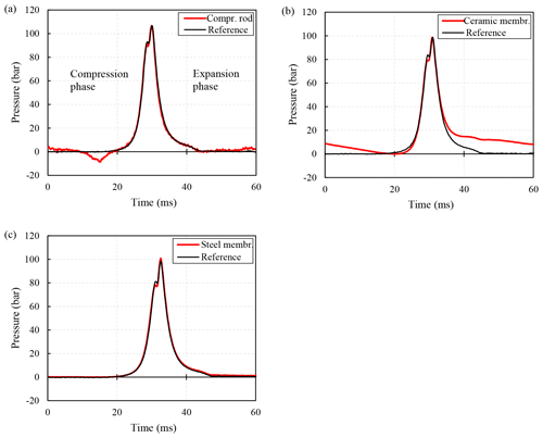
Figure 8Time-resolved pressure curves of one exemplary combustion cycle for each sensor concept (a force compression rod, b ceramic membrane type, c steel membrane type). The data were recorded at 1900 rpm and 150 Nm torque of the diesel engine.
In case of the non-intrusive force compression rod a total of two specimens were assembled, showing similar properties. The signal of one sensor is depicted in Fig. 8a. It matches that of the reference sensor very well. Even small details like the first pressure peak at 29 ms (milliseconds) are detected. Based on the calibration, the prototype has a sensitivity of approx. 7.9 µV (V bar)−1, corresponding to the predicted sensitivity of 6.9 µV (V bar)−1 by our structural FE analysis. A peculiar difference to the reference is a negative peak at 15 ms. At that time the neighbour cylinder exhibits its maximum combustion pressure. Hence, the pre-load force of the compression rod is reduced due to mechanical coupling, resulting in a negative peak. This inner-cyclic disturbance has the same frequency as the pressure signal. That may be a problem, if for instance in a multi-cylinder inline engine, a simultaneous ignition in one of the neighbouring cylinders occurs. In this circumstance, the negative peak would superimpose the pressure peak, leading to false pressure values.
Figure 8b showcases a signal gathered by means of the intrusive membrane-type sensor made of zirconia ceramics. The calibrated sensitivity is about 32 µV (V bar)−1, which is comparable to that obtained on the static pressure test bench (30.7 µV (V bar)−1 at 180 ∘C). This sensitivity is higher by a factor of 4 compared to the compression rod. The signal also shows an inner-cyclic deviation in the compression phase as well as in the expansion phase of the combustion cycle. The maximum deviation of approx. 11 bar occurs at 50 ms. This influence is likely caused by the heat strike onto the membrane during fuel burning and an associated inner-cyclic change in the thermal gradient across the membrane. Such thermal shock effects were also observed in other cylinder pressure sensor applications with piezoelectric elements, discussed by Hart (1999). Although the depicted pressure curve was taken at lower power, the changing temperature gradient produces a detrimental inner-cyclic signal distortion. In addition, due to the low thermal conductivity (2.5 W (m K)−1) of the zirconia material, the thermal FE analysis predicts a temperature gradient of up to 30 K from the centre to the membrane's periphery at maximum engine power. This probably results in a reduced zero-point stability over temperature. The amplitude of the distortion is determined by the temperature gradient and the TCR of the Wheatstone bridge resistors, being relatively high at 1200 ppm K−1 in this case. By adjusting the sputtering process, we were able to reduce the TCR to less than 100 ppm K−1, but this time the sensors failed for another reason. The thin films were destroyed at the operating temperature due to the starting oxygen ion conductivity of zirconia under DC excitation. As a bottom line we have to consider that zirconia elements are not suitable for this application.
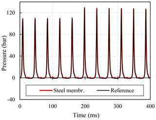
Figure 9Chronological sequence of several combustion cycles measured with the steel membrane prototype sensor and the reference pressure sensor. At a constant rotation speed of 3200 rpm of the diesel engine, the torque was increased from 150 to 200 Nm in this cut-out sequence.
The third sensor concept to be tested in the diesel engine, was the steel membrane type. Overall four sensors were built, which have comparable characteristics. The calibrated signal of one sensor is depicted in Fig. 8c. In this case a nearly perfect congruence with the reference signal is found, without any measurement artefacts. The sensitivity is approx. 87 µV (V bar)−1 and the maximum deviation is below 2 bar (< 1 % full scale). The higher sensitivity can be explained by the different geometric dimension of the steel membrane compared to the ceramic version and by an improved chromium thin film (Schwebke and Schultes, 2019) as strain gauge material. The thermal shock behaviour is obviously improved by using a steel membrane, a material with a relative high thermal conductivity of 16 W (m K)−1. Not only is the thermal shock error reduced, but also the maximum temperature on the membrane is significantly lower as we showed in Fig. 7b. Of the two membrane materials, steel is clearly preferred. Table 3 gives an overview of the main sensor characteristics of the examined sensor concepts.
In addition to the representation of one pressure peak (Fig. 8c), a sequence of several combustion cycles is depicted in Fig. 9, again with both sensors. The torque of the diesel engine was changed from 150 to 200 Nm at 3200 rpm in this course. Surprisingly, the change effectuates a pressure rise from one cycle to the next, as is obvious at 200 ms in the chart of Fig. 9. Both sensors deliver nearly identical signals. We point out that neither the amplitude nor the zero point exhibit a significant deviation of more than 2 bar. This behaviour supports the result that thermal influences are clearly reduced by the relatively high thermal conductivity of steel.
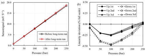
Figure 10(a) Raw sensor output signal before and after the long-term run of the steel membrane, measured on the static test bench at 230 ∘C. (b) Linearity deviation of the steel membrane sensor after the long-term run at 230 ∘C.
For an endurance test one of the steel membrane sensors was tested during 20 million cycles on a gasoline engine, as mentioned in Sect. 2. The sensor withstands the long-term stress without any malfunction and was characterized before and after the test with respect to zero point, sensitivity, linearity, and hysteresis.
In Fig. 10a, two measurements are plotted to compare the sensor characteristics before and after the long-term run. The measurements were carried out at 230 ∘C in the static pressure test bench. The sensitivity is increased by approx. 2 % after the test, probably due to thin film aging at higher temperatures. Other parameters like the bridge zero signal and the linearity error show no significant changes. Before and after the test, the linearity error is less than ±0.3 % full scale and the offset change is less than 0.3 mV V−1. These variations may also be caused by different mounting torques during the installation of the sensors. Figure 10b illustrates the linearity deviation after the long-term run of three consecutive measurements at 230 ∘C. In this type of diagram only the deviation from absolute linearity is plotted. The measurement indicates a good repeatability with respect to the sensitivity, linearity deviation of less than −0.3 %, and a hysteresis of approx. 0.25 %. This result shows a good performance of the steel membrane-type sensor at elevated temperature after the long-term test.
In this research different principles of cylinder pressure sensors were investigated, namely a non-intrusive compression rod with foil strain gauges and two versions of real in-cylinder or intrusive membrane-type pressure sensors. The time-resolved evolution of the combustion pressure can be measured with all three types of sensors, but there are important differences with pros and cons to be considered.
The non-intrusive force compression rod works on a very moderate temperature level of approx. 120 ∘C, because the sensor elements are not in contact with the combusting gas mixture. This principle would be best suited for long-term stability regarding the low thermal demand, the robust construction and the immunity against soot deposits. However, as the sensor measures only a fraction of the force generated by the combustion, its sensitivity strongly depends on the mounting position and the mechanical stiffness of the surrounding construction. Hence, the calibration has to be performed after the sensor installation. Furthermore, ignitions in neighboured cylinders may influence the pressure measurement if the force compression rod is used in a multi-cylinder inline engine. On the other hand, this disturbance should not be present by using the sensor in a combustion engine where the cylinders have no direct neighbours (e.g. single-cylinder engine, two-cylinder V- or Boxer engine). The compression rod may also be advantageous on big engines (for ships and trucks), due to its inherent insensitivity to soot deposits and the very moderate temperature level.
The intrusive membrane-type sensors develop higher temperature levels, because they are directly exposed to the combustion heat and pressure. The thermal conductivity of the membrane material turns out to be a very crucial parameter. If a zirconia-based material is employed, a temperature level of approx. 300 ∘C arises, instead of only about 200 ∘C for the steel membrane. This is the consequence of a thermal conductivity of 2 W (m K)−1 compared to 16 W (m K)−1. Not only the temperature level, but also the temperature gradient on the membrane is higher if the material with the lower thermal conductivity is used. This gradient and the gradient variance in combination with the TCR of the thin film is accountable for significant signal disturbances. In addition, the starting oxygen ion conductivity of the zirconia ceramic under DC excitation will damage the thin sensor film. Consequently, the zirconia-based element is not suitable for this application.
For the steel membrane variant, the thermal shock behaviour is radically minimized due to the relatively high thermal conductivity of steel and the low TCR of the thin film. The thermal conductivity reduces the overall temperature and the thermal gradient. The steel-based membrane sensor delivers signals nearly identical to the reference sensor. By testing the sensor over 20 million combustion cycles, we proved that the sensor characteristics are unaffected. Our robust construction with only a few parts compared to other more complex available cylinder pressure sensors as well as the lower temperature level let us anticipate good and long-term reliably functionality. The newly developed electrical connection, made by laser welding a copper wire directly onto the thin film, is feasible on the steel membrane. This welded contact works without additional solder material and withstands high temperatures and a high mechanical load.
Compared to state-of-the-art cylinder pressure sensors such like the Beru PSG, the developed sensor systems use novel thin films, which have the capability to withstand higher temperatures of up to 300 ∘C and show simultaneously higher strain sensitivities of up to 15. In addition, the investigated sensor systems have fewer components, which simplifies the sensor assembly.
For further investigations, the favoured steel membrane version will be combined with the electronic version that is developed in a parallel process into one sensor unit. The algorithms to be implemented will perform a real-time computation of aggregated and meaningful parameters such as the MFB50 or the mean effective pressure, to allow for smart combustion control.
The underlying measurement data are not publicly available and can be requested from the authors, if required.
DV developed and performed most of the experimental work. He analysed the measurements and prepared the paper. DW designed the intrusive version of the steel element, acquired the measurement data and established the thermal FE simulation. TK contributed different shapes of the non-intrusive compression rod and helped with mechanical adaptions. GS prepared the paper with contributions from all authors. All authors contributed to the discussions.
The authors declare that they have no conflict of interest.
This article is part of the special issue “Sensors and Measurement Systems 2018”. It is a result of the “Sensoren und Messsysteme 2018, 19. ITG-/GMA-Fachtagung”, Nürnberg, Germany, from 26 June 2018 to 27 June 2018.
The authors would like to thank all members of the smart combustion project conducted at the htw saar University of Applied Sciences. The diesel and the Briggs & Stratton test benches were modified and operated by Thomas Heinze, Michael Fries, and Peter Birtel. The measurements on the test benches were further analysed by Hans-Werner Groh and Peter Gibson. We thank them for helpful assistance and fruitful discussions.
The work was funded by the Federal Ministry of Education and Research of
Germany (BMBF) under the program FHprofUnt2015 (project funding reference
number 13FH010PX5). The financial support is gratefully acknowledged. The
steel sensor elements were supplied by Kavlico GmbH.
Edited by: Walter Lang
Reviewed by: two anonymous referees
Böhler: Technical datasheet, available at: https://www.bohler-edelstahl.com/de/N700.php, last access: 15 August 2018.
Farahmand, B. and Nikbin, K.: Predicting fracture and fatigue crack growth properties using tensile properties, Eng. Fract. Mech., 75, 2144–2155, doi.org/10.1016/j.engfracmech.2007.10.012, 2008.
Gustafsson, P., Kolavcic, P., and Lifvenborg, U.: Pressure sensor for measurement of gas pressure in a cylinder of a combustion engine, US Patent, US6561036B1, 1998.
Hart, M.: Auswertung direkter Brennrauminformationen am Verbrennungsmotor mit estimationstheoretischen Methoden, PhD thesis, University of Siegen, 1999.
Hellemans, A., Landrevie L., Venzal S., and Walker E.: Direkte Zylinderdruckmessung, MTZ Motortechnische Zeitschrift, 72, 770–776, https://doi.org/10.1365/s35146-011-0172-6, 2011.
Hidria: Glow plug with integrated pressure sensor, available at: http://www.hidria.com/en/about-us/projects-references/5226/detail.html, last access: 2 August 2018.
Kistler: Combustion Analysis in Vehicles and on the Test Bench, available at: https://www.kistler.com/en/applications/automotive-research-test/engine-research-development/combustion-analysis-cylinder-pressure-testing/, last access: 2 August 2018.
Kondo, M., Niimi, A., and Nakamura, T.: Indiscope – A New Combustion Pressure Indicator with Washer Transducers, in: SAE Technical Paper 750883, https://doi.org/10.4271/750883, 1975.
Langosch, M., Cerino, M., Landes, A., Lellig, A., Vollberg, D., Göttel, D., Probst, A-C., Freitag-Weber, O., and Schultes, G.: Pattern definition of foil based sensors with ultrafast uv-lasers, in: Proceedings of the AMA Conferences 2015 – Nuremberg, 755–758, https://doi.org/10.5162/sensor2015/P2.1, 2015.
Last, B., Müller, H., Pottiez, C., Rixecker, G., and Stoller, B.: Cylinder pressure sensor, German Patent, DE102009050911A1, 2009.
Microceram: Technical datasheet, available at: https://www.microceram.de/assets/File/MicroCeram_englisch.pdf, last access: 12 August 2018.
Parra, F.: Heat transfer investigations in a modern diesel engine, PhD thesis, 118–119, University of Bath, 2008.
Powell, J.: Engine Control Using Cylinder Pressure: Past, Present, and Future, J. Dyn. Syst.-T. ASME, 115, 343–350, https://doi.org/10.1115/1.2899074, 1993.
Saitzkoff, A., Reinmann, R., Mauss, F., and Glavmo, M.: In-Cylinder Pressure Measurements Using the Spark Plug as an Ionization Sensor, in: SAE Technical Paper 970857, https://doi.org/10.4271/970857, 1997.
Schiefer, D., Maennel, R., and Nardoni, W.: Advantages of Diesel Engine Control Using In-Cylinder Pressure Information for Closed Loop Control, in: SAE Technical Paper 2003-01-0364, https://doi.org/10.4271/2003-01-0364, 2003.
Schultes, G., Cerino, M., Langosch, M., Kuberczyk, T., Vollberg, D., Göttel, D., Freitag-Weber, O., and Probst, A-C.: Drucksensoren aus Zirkonoxid-Keramik mit hochempfindlichen Sensorschichten, Tech. Mess., 83, 147–156, https://doi.org/10.1515/teme-2015-0096, 2015.
Schultes, G., Schmid-Engel, H., Schwebke, S., and Werner, U.: Granular metal-carbon nanocomposites as piezoresistive sensor films – Part 1: Experimental results and morphology, J. Sens. Sens. Syst., 7, 1–11, https://doi.org/10.5194/jsss-7-1-2018, 2018.
Schwebke, S. and Schultes, G.: Strain sensitive Chromium sensor thin films, in preparation, 2019.
Schwebke, S., Werner, U., and Schultes, G.: Granular metal-carbon nanocomposites as piezoresistive sensor films – Part 2: Modeling longitudinal and transverse strain sensitivity, J. Sens. Sens. Syst., 7, 69–78, https://doi.org/10.5194/jsss-7-69-2018, 2018.
Sellnau, M., Plyler, R., and Rodondi, A.: Non-intrusive cylinder pressure sensor, US Patent, US5329809A, 1993.
Sellnau, M., Matekunas, F., Battiston, P., and Chang, C.: Cylinder-Pressure-Based Engine Control Using Pressure-Ratio-Management and Low-Cost Non-Intrusive Cylinder Pressure Sensors, in: SAE Technical Paper 2000-01-0932, https://doi.org/10.4271/2000-01-0932, 2000.
Sensata: Cylinder pressure-only sensors (CPOS), in: Sensor Solutions For Heavy Duty Applications, Technical brochure, 36–37, available at: https://www.sensata.com/resources/sensor-solutions-heavy-duty-applications-brochure (last access: 2 August 2018), 2015.
Simon, S. and Krebs, H.: Fuel injection valve and pressure sensor combination, US Patent, US6318342B1, 1999.
Smithells, C. J.: Metals Reference Book, 7th Edition, chapter 11, 259, ISBN: 9780080517308, 2013.
Ulrich, O., Wlodarczyk, R., and Wlodarczyk, M.: High-Accuracy Low-Cost Cylinder Pressure Sensor for Advanced Engine Controls, in: SAE Technical Paper 2001-01-0991, https://doi.org/10.4271/2001-01-0991, 2001.
Ura, Y. and Oya, K.: Pressure Sensor Module for High Temperature, High Pressure, and Quick Response, in: SAE Technical Paper 2018-01-0759, https://doi.org/10.4271/2018-01-0759, 2018.
Vollberg, D., Probst, A-C., Langosch, M., Landes, A., Göttel, D., Cerino, M., Lellig, A., Freitag-Weber, O., and Schultes, G.: Hochempfindliche Folien-Dehnungsmessstreifen auf dem Weg zur technologischen Reife, Tech. Mess., 82, 506–516, https://doi.org/10.1515/teme-2015-0066, 2015.


