the Creative Commons Attribution 4.0 License.
the Creative Commons Attribution 4.0 License.
 | 23 Apr 2021
Absolute calibration of the spectral responsivity of thermal detectors in the near-infrared (NIR) and mid-infrared (MIR) regions by using blackbody radiation
Tobias Pohl
Peter Meindl
Lutz Werner
Uwe Johannsen
Dieter Taubert
Christian Monte
Jörg Hollandt
The Physikalisch-Technische Bundesanstalt (PTB) has set up an additional measurement approach for the absolute calibration of the spectral responsivity of detectors in the near-infrared (NIR) and mid-infrared (MIR) spectral range. This alternative method uses the radiation of a blackbody operating at about 1200 K with a precision aperture. The blackbody radiation can be calculated by Planck's law and is additionally spectrally selected by accurately characterized optical bandpass filters. Thus, a calibration of the spectral responsivity of a detector with respect to irradiance can be achieved at the bandpass wavelength of the applied transmission filters. If the aperture of the detector is known, the spectral responsivity can also be calculated with respect to radiant power.
Thermopile detectors with known aperture size were calibrated in terms of their spectral responsivity with several bandpass filters in the spectral range between 1.5 µm up to 14 µm with relative standard measurement uncertainties between 5 % and 19 %. The obtained results are consistent with previous calibrations at PTB's national primary detector standard. Therefore, this additional measurement approach is a further validation of the existing primary method which is based on a cryogenic radiometer and extends the usable wavelength range.
- Article
(1427 KB) - Full-text XML
- BibTeX
- EndNote


Currently, the calibration of detectors regarding their spectral responsivity in the spectral range of the near-infrared (NIR) and mid-infrared (MIR) is of increasing interest and market importance, e.g. for remote sensing (Allison et al., 2016; Sobrino et al., 2016) or radiation thermometry (Noulkow et al., 2009). These applications need traceability to the International System of Units (SI). Therefore, the Physikalisch-Technische Bundesanstalt (PTB) operates cryogenic electrical substitution radiometers as primary detector standards to measure radiant power traceable to the SI with low uncertainty and to calibrate other types of detectors regarding their spectral responsivity by relating the output of these detectors to the measured radiant power (Hartmann et al., 2010). Appropriate detectors, which have been calibrated absolutely against the primary detector standards, can also be used for the dissemination of the spectral responsivity to other detectors. The PTB uses different types of such transfer detectors to facilitate the dissemination of the spectral responsivity.
In the NIR and MIR, many of these transfer detectors are thermal detectors, whose measurement principle is based on the heating effect of an absorber. Therefore, the detector responsivity is spectrally more or less wavelength independent as long as the absorption of the incident radiant power is independent of the wavelength and there is no other spectrally selective element (e.g. a window). A sufficiently accurate interpolation of the spectral responsivity between widely separated calibration wavelengths is possible in this case (Taubert et al., 2017).
Recently, the PTB realized an additional approach for detector calibrations regarding the spectral responsivity traceable to the SI by using a large-area blackbody radiator (called LABB) operating at about 1200 K with a precision aperture as a standard of spectral irradiance. In this case the responsivity of a detector is not found by comparison to another detector but by using the radiation of a calculable radiation source.
Figure 1 shows the measurement setup for the calibration of detectors regarding their spectral responsivity. The spectral responsivity s(λ) is the ratio between the output signal of the detector and the received radiant power.
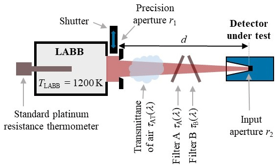
Figure 1Measurement setup for the detector calibration regarding the spectral responsivity at the large-area blackbody (LABB) with a precision aperture and two transmission filters.
The realized concept of the calibration of the spectral responsivity uses the radiation of a calculable radiation source: an almost ideal blackbody radiator is used as a source of thermal radiation. Hence, the spectral radiance is described by Planck's law for the specific temperature and emissivity. The spectral radiant power at the detector can be calculated from the spectral radiance if the geometry of the setup is known. This geometry is determined by the size of the radiator aperture, the size of the detector input aperture and the distance between both apertures. Furthermore, the transmittance of the air must be taken into account.
A small spectral part of the thermal radiation is selected by using different spectral bandpass filters to obtain information about the wavelength dependency of the detector responsivity. Well-characterized pairs of filters have been applied which are slightly tilted at an angle of 6∘ to avoid interreflections between them.
The spectral responsivity of the detector can be calculated if all of the mentioned influencing quantities are known, and the corresponding signal of the detector is additionally measured.
2.1 Large-area blackbody radiator (LABB)
The blackbody radiator that is used has a comparatively large aperture to provide a larger irradiance in front of the cavity. It is named large-area blackbody (LABB) for this reason. It has an emissivity ε of 0.9990 and very small temperature inhomogeneities, and it is therefore an almost ideal realization of a blackbody radiator (Taubert, 2003). The LABB consists of two concentrically stacked heat pipes with an inner radius of 77.5 mm and a temperature-stabilized precision aperture with a nominal radius r1 of 10 mm. A temperature-stabilized shutter is used to block the radiation for the measurement of the detector dark signal.
The temperature of the LABB is measured with standard platinum resistance thermometers (SPRTs), and the temperature stability during one measurement cycle is better than 50 mK. The SPRTs are calibrated at PTB's fixed point cells for silver (TAg=1234.93 K), aluminium (TAl=933.47 K), zinc (TZn=692.68 K) and tin (TSn=505.08 K) as well as the water triple point cell ( K). These fixed point cells are realizations of the International Temperature Scale of 1990 (ITS-90) and the uncertainty of the calibration is 10 mK.
All optical components are mounted on an optical bench to ensure an optimal and collinear alignment with the heat pipes of the LABB. The distance d between the apertures of the LABB and the detector was set to about 400 mm, which was measured with a calibrated inside micrometre gauge.
2.2 Filter transmission measurement
The spectrally broad thermal radiation of the blackbody radiator has to be restricted to a certain wavelength range to calibrate detectors in terms of their spectral responsivity. A combination of two well-characterized optical filters has been used for each calibration wavelength: a bandpass filter (“filter A”) combined with an additional wider bandpass filter or an edge filter (“filter B”). The use of two filters significantly improves the attenuation of the out-of-bandpass radiation and reduces possible unintentional transmission in the blocking range of one of the filters. So, the compilation of two filters improves the ratio between the wanted radiation in the narrow bandpass wavelength range and the unwanted radiation in the wide out-of-bandpass wavelength range. Simultaneously, the transmission in the bandpass range is only slightly reduced when using two suitable filters.
Several pairs of filters have been chosen and characterized for their transmittance in the spectral bandpass and in the blocking range by using a Fourier transform spectrometer (FTS) and additionally a monochromator-based spectral measurement facility at the PTB. In principle, the filters need to be characterized over the whole spectral range, where the LABB emits radiation as described by Planck's law. Therefore, different radiation sources, beam splitters and detectors were used at the FTS measurement facility to cover the spectral range from 400 nm in the visible (VIS) up to 200 µm in the far infrared (FIR). The uncertainty of the filter transmission measurement and its contribution to the combined measurement uncertainty of the detector calibration will be discussed in detail in Sect. 4.
Figure 2 shows the FTS measurement results and the calculated transmittance of two filters for calibrations at 1.55 µm. Similar pairs were characterized for calibration wavelengths at 2.7 µm, 3.9 µm, 10.6 µm and 14 µm. The filters with a diameter of about 25 mm are produced by different manufacturers.
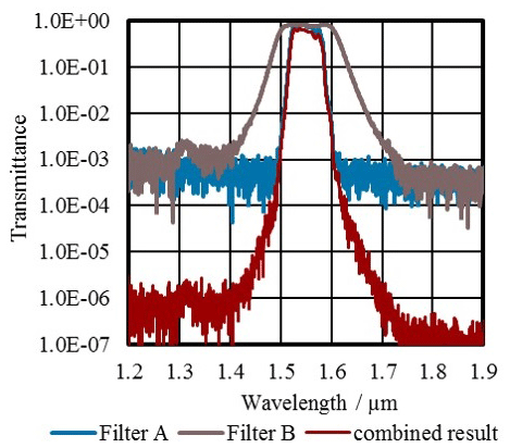
Figure 2Transmittances of two filters with bandpass regions at 1.55 µm measured with a Fourier transform spectrometer (blue and brown) and the calculated resulting transmission of both filters combined (red) with significantly improved out-of-bandpass blocking.
In general, the spectral responsivity s(λ) of a detector is the wavelength-dependent ratio between the output signal U of the detector and the radiant power Φ which is irradiating the detector at a certain wavelength:
The spectral responsivity of the detector is considered to be constant within the wavelength range of the bandpass of the applied transmission filters. The resulting spectral responsivity is assigned to the central bandpass wavelength of the filter pair. However, this bandpass is dominated by filter A, which was always the filter with narrower bandwidth. Consequently, the spectral responsivity is assigned to the central bandpass wavelength λBP-A of filter A, whereas the detector signal and the radiant power has to be calculated for the filter combination:
The determination of the radiant power in the filter bandpass ΦBP-AB and the detector output signal UBP-AB will be described in the following.
3.1 Calculation of the radiant power in the filter bandpass
The spectral radiance Lλ(λ, TLABB) of the LABB with its wavelength-independent emissivity ε can by calculated by Planck's law:
This spectral radiance Lλ(λ, TLABB) is then reduced by the spectral absorptance of radiation by the air in the beam path with distance d. Absorption of radiation in air is mainly caused by water molecules, as well as by nitrogen, oxygen and carbon dioxide. Hence, the air humidity was monitored during the calibration procedure. All these molecules are considered by the software HITRAN, which calculates the spectral transmittance τAT(λ) of the ambient atmosphere by using a comprehensive and validated data set for the spectral absorption of molecules (Rothmann et al., 2013).
The refractive index n of air for standard conditions can be found in literature (e.g. Kohlrausch, 1996), and its uncertainty can be estimated with Edlen's formula for potential changes of the temperature, pressure and humidity (Bönsch and Potulski, 1998).
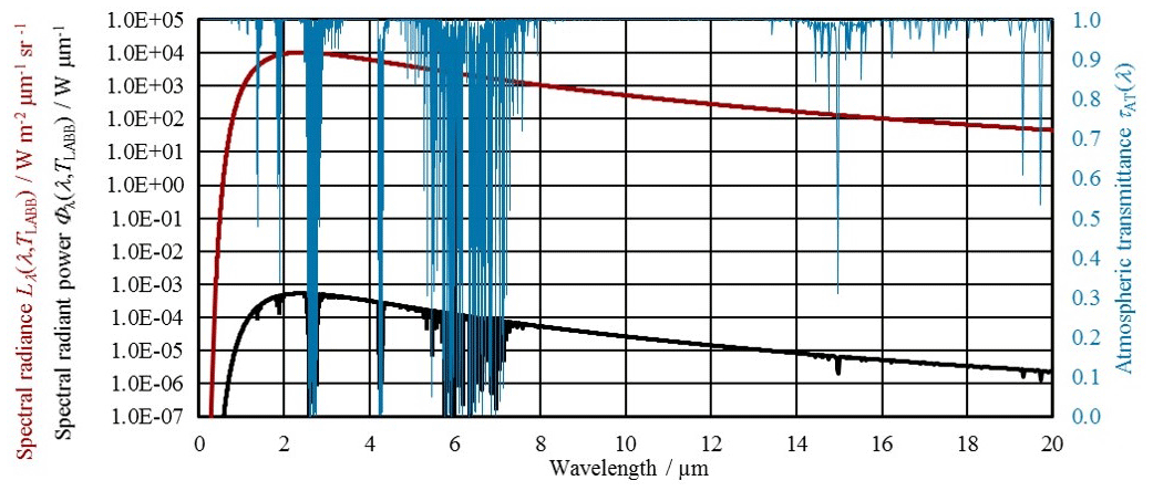
Figure 3The spectral radiance Lλ(λ, TLABB) of the LABB as given by Planck's law for a temperature of 1200 K (red), the transmittance of 400 mm atmosphere τAT(λ) (blue) and the obtained spectral radiant power Φλ(λ, TLABB) for the geometry at the calibration setup (black).
The circular radiator and detector apertures with radii r1 and r2 are coaxially aligned at the distance d. Therefore, the spectral irradiance Eλ(λ, TLABB) in the plane of the detector aperture is given by (Taubert, 2003):
The spectral radiant power Φλ(λ, TLABB) is calculated by multiplying the spectral irradiance Eλ(λ, TLABB) with the detector input aperture size:
The geometry of the measurement setup can by summarized with the geometry factor G:
The radiation of the LABB is then spectrally selected by the applied bandpass filters with its transmittances τA(λ) and τB(λ). Therefore, the radiant power Φ(TLABB) irradiating the detector is given by integration of the spectral radiant power Φλ(λ, TLABB) multiplied by the filter transmittances over all wavelengths:
Only the part of the radiant power ΦBP-AB which irradiates the detector in the wavelength range of the bandpass of filter A is used for the determination of the spectral responsivity s(λBP-A):
Consequently, the measured detector signal which is generated by the total amount of radiant power Φ(TLABB) needs to be corrected with respect to the out-of-bandpass radiation. This will be explained in the Sect. 3.2.
Figure 3 shows the spectral radiance Lλ(λ, TLABB) and the obtained spectral radiant power Φλ(λ, TLABB) at the detector. The LABB is set at its maximum temperature of 1200 K, and the shortest possible distance d of about 400 mm between the LABB and the detector is realized to achieve high power levels at the detector. As mentioned above, it is necessary to produce a high level of radiation in the bandpass wavelength range while the radiation in the out-of-bandpass wavelength range has to be as small as possible. Two main aspects have an impact on this relation:
-
The calibration wavelength. The maximum of the spectral radiance as calculated by Planck's law at the blackbody temperature of 1200 K is in the wavelength range around 2.5 µm. This results in a relatively high amount of radiation in the bandpass region and comparatively low radiant power in the out-of-bandpass radiation for calibrations in this wavelength range. In contrast, for calibrations at longer wavelengths, for instance at 14 µm, the spectral radiance in the bandpass wavelength range is significantly lower and at the same time, the predominant part of the emitted thermal radiation needs to be blocked by the filters.
-
The characteristics of the applied filters. The transmittance τBP in the bandpass region should be as high as possible to achieve high input levels. For the same reason, the bandwidth Δλ of the filters should also be rather wide. However, the maximum bandwidth was chosen to be about 1 µm to ensure that a possible change of the spectral responsivity s(λBP-A) within the bandpass can be neglected. Furthermore, the bandpass wavelength λBP of the filters should be chosen in spectral ranges with low atmospheric absorption. Apart from that, it is a crucial requirement for the bandpass filters to block nearly all out-of-bandpass radiation in the wide spectral range from VIS to FIR. The out-of-bandpass (or blocking) transmittance τBL in the spectral range between 2 µm and 10 µm is in this case of special interest because the spectral radiance Lλ(λ, TLABB) reaches its maximum in that spectral range (see Fig. 3).
Unfortunately, the option of reducing the blackbody temperature TLABB to shift the spectral maximum towards the bandpass wavelength especially for calibration wavelengths above 10 µm results in a decline of the bandpass radiation below the detection limit of the detectors (which typically is about 1 µW). The usage of three or more filters simultaneously is not suitable for the same reason, because the radiation in the bandpass wavelength range would also become insufficient. Typically, a radiant power ΦBP-AB in the range between 1 µW and 20 µW has been realized at the calibration setup by using different combinations of two filters.
3.2 Correction of the measured detector signal for out-of-bandpass radiation
Although the radiant power at the detector is mainly in the spectral range of the bandpass of the applied transmission filters, a small but significant value of transmitted radiant power reaches the detector in the wide out-of-bandpass spectral range, which is caused by remaining transmittance in the blocking range. To determine the part of the detector signal UBP-AB that is only caused by the amount of radiant power in the spectral range of the filter bandpass, the total detector signal Utotal needs to be reduced by the part of the detector signal Ublock which is caused by radiant power in the spectral blocking range of the filters:
The total detector signal Utotal in this calculation is already corrected with respect to the detector dark signal, which is measured by using a temperature-controlled shutter between the blackbody aperture and the blackbody.
The portion Ublock of the detector signal can be evaluated by estimating the detector's spectral responsivity in the spectral blocking range of the filter. As a first approximation, the spectral responsivity is considered to be independent of the wavelength. This approximation of the spectral responsivity can be improved to lower the uncertainty by incorporating previous calibrations and characterizations of the absorber layer in the wavelength range up to 25 µm (see Eqs. 11 and 12). The spectral responsivity at wavelengths above 25 µm (see Eq. 13) is based on a rough assumption with higher uncertainty. Figure 4 shows the model for the spectral responsivity of the detector under test.

Figure 4Model for the spectral responsivity in the out-of-bandpass range (red) including the uncertainty of this assumption (grey) in line with the transmittance of the bandpass filter A (blue).
In terms of the wavelength ranges defined in Eqs. (11)–(13), the corrected detector output signal is calculated by
with the radiant power Φij in the specific wavelength range from λi to λj:
The wavelengths λ2, λ5 and λ7 shown in Fig. 4 which are not used in Eqs. (14) and (15) will be explained and used later (e.g. in Fig. 5).
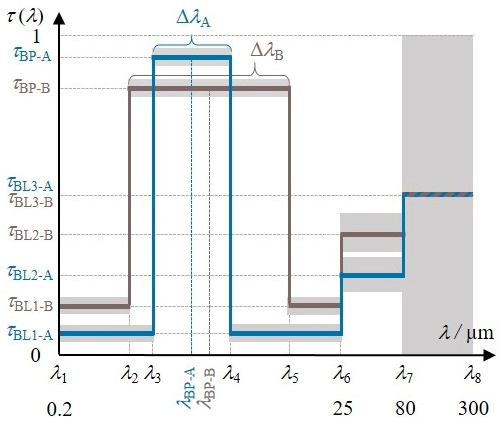
Figure 5Parametrization of the transmittances of the filters A and B including their uncertainties in different spectral ranges (grey) for the consideration of the transmittance measurements in the calculation of the measurement uncertainty of the spectral responsivity.
3.3 Correction of the spectral responsivity for stray radiation
The spectral responsivity – which is calculated as the ratio between the out-of-bandpass corrected detector signal UBP-AB and the radiant power in the filter bandpass ΦBP-AB – has furthermore to be corrected with respect to stray radiation. Stray radiation mainly occurs in two ways at the calibration setup:
-
A small part of the blackbody radiation is scattered alongside the bandpass filters and reaches the detector's sensitive area by multiple reflections at the optical components, which are needed to realize the calibration setup. Additional stray radiation apertures have been implemented to reduce this stray radiation to a minimum and to limit the field of view of the detector. The size of these apertures is as small as possible to block as much of this stray radiation, but it is still large enough to not limit the actual beam path through the filters between the LABB aperture and detector aperture. Comprehensive measurements with blocked bandpass filters have been conducted to prove that there is no significant stray radiation alongside the optical components left.
-
Further stray radiation is generated since the detector aperture in front of the sensitive area is exposed to the blackbody radiation. This radiation is scattered from the detector aperture onto optical components in front of the detector and then back onto the sensitive area of the detector. Therefore, a correction factor aSR of the calibrated spectral responsivity is added to the calculation of the spectral responsivity. The correction factor is based on measurements with different apertures as 0.980, and its associated uncertainty is conservatively estimated as 0.020.
The final equation for the determination of the spectral responsivity including all corrections and applying the wavelength ranges as shown in Fig. 4 and the substitutions from Eq. (15) is then given by
In the following, the determination of the measurement uncertainty of the spectral responsivity obtained with the calibration method at the blackbody radiator LABB will be presented. According to the Guide to the Expression of Uncertainty in Measurement (GUM) (BIPM, 1995), the combined standard measurement uncertainty uc for multiple uncorrelated input parameters xi for the function s(x1, x2, …, xn) has to be calculated by
The equation to determine the spectral responsivity for the detector calibration at the LABB with optical bandpass filters is given in Eq. (16) and includes the following input parameters: detector signal Utotal; aperture radius of the LABB r1; aperture radius of the detector r2; distance d; emissivity ε; temperature TLABB; absorption in air τAT(λ); refractive index of air n; the spectral responsivities s1, s2, and s3; transmittances of filters A and B; and the correction factor aSR.
The filter transmittances τA(λ) and τB(λ) are wavelength dependent and therefore part of the integrals in Eq. (16). For this reason, it would be laborious to calculate the sensitivity factors with respect to the filter transmittances τA(λ) and τB(λ). Therefore, a simplified model for the consideration of the filter transmittance in the uncertainty calculation was applied to calculate the measurement uncertainty with a reasonable mathematical effort: in this model the filter transmittance is hypothesized to be wavelength independent in certain spectral ranges. Hence, the filter transmittances can be factored out from the integrals in Eq. (16). Note that this simplified consideration of the filter transmittance is only used for the uncertainty calculation but not for the determination of the spectral responsivity itself!
4.1 Model for the consideration of the uncertainty of the filter transmittance in the uncertainty budget
The filter transmittance is assumed to be section-wise constant in the applied simplified mathematical model for the uncertainty calculation. This allows us to describe the filter transmittance with only a few parameters, which are for both filters the central bandpass wavelength λBP; the bandwidth Δλ; the transmittance τBP in the bandpass; and the transmittances τBL1, τBL2, and τBL3 in different sections of the out-of-bandpass range, as shown in Fig. 5.
Each parameter features a specific uncertainty contribution. Thereby, the different uncertainties of the filter transmittance measurements in diverse wavelength ranges at the FTS are taken into account. Furthermore, the model correctly considers the correlation between the shift of the upper and lower bandpass wavelength e.g. due to tilting, because a shift of the central wavelength impacts both the upper and lower bandpass edge.
The formula of the spectral responsivity that is used for the determination of the uncertainty is significantly simplified by implementing the parametrization of the filter transmittances for all pairs A and B with the assumption of section-wise wavelength-independent transmittances:
Equation (18) uses the substitutions Kij for the integrals:
and a simplification of the geometry factor G in the present measurement setup with and :
In Eq. (18), the transmittances are no longer part of the integrals; therefore, the partial derivations can be evaluated with reasonable mathematical effort to determine the sensitivity coefficients for the uncertainty u(xi) of each input quantity xi.
4.2 Measurement uncertainties connected with the filter transmittances
The uncertainties of the filter transmittances are the dominating contributions towards the combined measurement uncertainty of the spectral responsivity and are therefore discussed in detail. The uncertainties are subdivided into the uncertainties of the transmittance measurements in the bandpass and out-of-bandpass wavelength ranges, as well as the local inhomogeneities and the instabilities of the filter transmittances. This also includes the uncertainty of the central bandpass wavelength.
The absolute standard uncertainty of the measurement of the transmittance in the out-of-bandpass range at the FTS is mainly caused by stray radiation, which was characterized by measurements with an aluminium sample instead of the filter. It is 0.0050 for wavelengths shorter than 25 µm and 0.015 for wavelengths up to 80 µm. In the wavelength range of the bandpass τBP, the absolute measurement uncertainty is 0.015.
Additional measurements were conducted at the FTS and a spectral comparator measurement facility to investigate the uncertainty contributions. The spectral comparator measurement facility is monochromator based and realizes measurement uncertainties better than 10−4.
Figure 6 displays the comparison of the transmittance measured with the FTS and with the spectral comparator facility for a filter with the central bandpass wavelength λBP at 1.55 µm. The transmittance in the bandpass range agrees within the measurement uncertainty of 0.015 and in the out-of-bandpass range of 0.0050 between these different measurement approaches. Figure 6 also shows the coherence of the bandpass shape between both measurements.
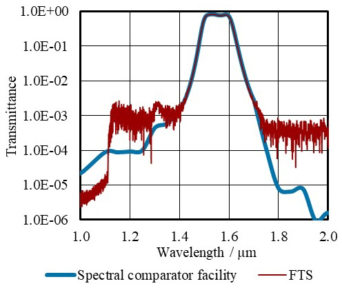
Figure 6Transmittance of a filter with its central bandpass wavelength at 1.55 µm measured with the Fourier transform spectrometer (FTS, red) and the spectral comparator facility (blue).
The transmittance of several filters was measured at different positions to evaluate the local inhomogeneity. The results for a filter with central bandpass wavelength λBP at about 4 µm show that the bandpass transmittance τBP varies in a range smaller than ±0.015 over the filter area (see Fig. 7). The stability of the central bandpass wavelength is better than ±15 nm. The overall shape of the bandpass is consistent, and the change of the filter bandwidth Δλ is smaller than ±3.0 nm.
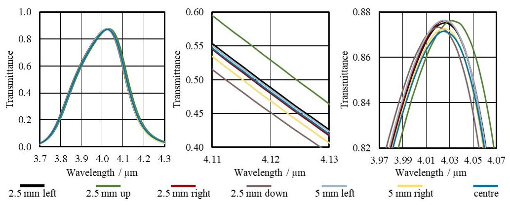
Figure 7Filter transmittance measured with FTS of a filter with its bandpass at about 4 µm at different local positions on the filter for evaluation of the local inhomogeneity of the spectral transmittance. Shown is the same measurement in different wavelength extracts.
Additional measurements were conducted to explore the uncertainty contribution due to misalignment such as small variances between the filter angle at the FTS and the LABB. These measurements took place at the FTS for several filters using sample holders with different tilt angles. The angle used during detector calibrations was 6∘. The tilting of the filters results in a shift of the central bandpass wavelength and a slight change of the bandpass transmittance. Figure 8 shows results for a filter with bandpass wavelength at about 10.6 µm. The bandpass transmittance τBP varies in a range smaller than ±0.015, and the wavelength accuracy is better than ±15 nm for tilt angle variations of ±2∘. The overall spectral shape of the filter bandpass does not change, and the variation of the bandwidth Δλ is insignificant.
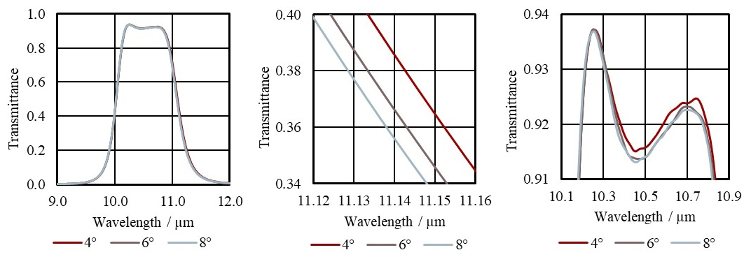
Figure 8Filter transmittance measured with FTS of a filter with its bandpass at about 10.6 µm for the investigation of the influence of different tilt angles on the spectral transmittance. The standard angle used during the calibrations is 6∘. Shown is the same measurement in different wavelength extracts.
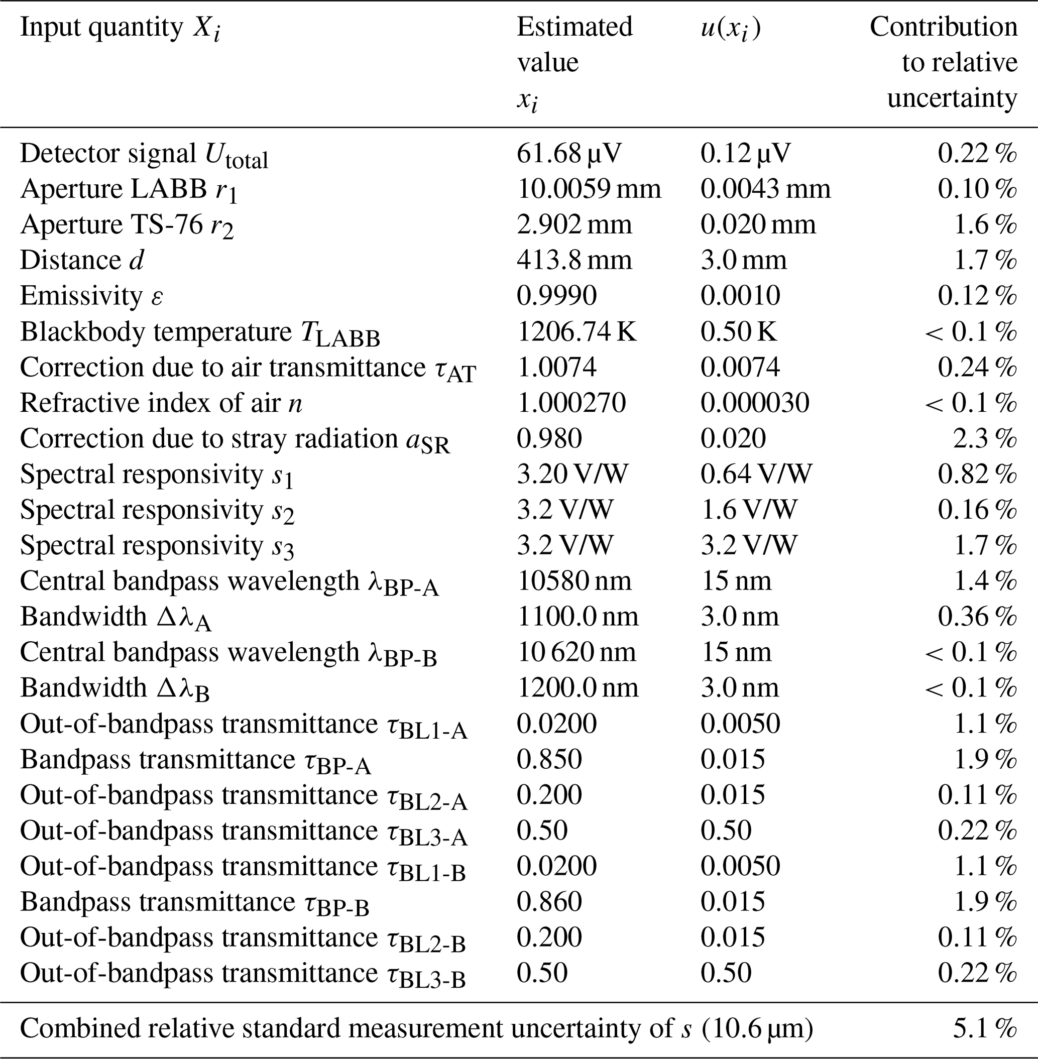
All investigated uncertainties of the filter transmittance due to the angle of incidence, the local inhomogeneity or the temporal instability are covered by the applied uncertainties u(λBP), u(Δλ), u(τBP), u(τBL1) and u(τBL2) as listed in Table 1. They are conveniently assumed to be the same for all filters.
Table 1List of all input quantities Xi, their estimated values xi and standard uncertainties u(xi) as well as their contributions towards the combined relative standard measurement uncertainty of the spectral responsivity of the thermopile detector TS-76 for the calibration at the blackbody radiator LABB with filters with a central bandpass wavelengths of about 10.6 µm. The values of the quantities for the filter model that is used for the calculation of the uncertainty are based on the measurement results of the Fourier transform spectrometer and former calibration results.
The radiant power in the spectral range below 80 µm – calculated by Planck's law for the blackbody temperature of 1200 K by also considering the atmospheric absorption (Eq. 7) – is about 12 000 times larger than the radiant power in the spectral range above 80 µm. Therefore, the filter transmittance at wavelengths above 80 µm can be conveniently estimated with without increasing the overall combined standard measurement uncertainty uc.
The described measurement approach using the calculable radiation of a blackbody combined with accurately characterized bandpass filters was applied to the calibration of a set of thermopile detectors (TS-76 by the Leibniz-Institut für Photonische Technologien e.V.). These detectors were equipped with additional apertures. The areas of these apertures have been separately determined (radius r2 around 2.9 mm measured with a standard uncertainty of 20 µm).
These detectors have been well characterized and are calibrated MIR transfer standards at the PTB (Pohl et al., 2019). The SI-traceable calibration of the spectral responsivity of these detectors has been accomplished against one of PTB's cryogenic electrical substitution radiometers, which are primary detector standards for the measurement of radiant power (Martin et al., 1985). These detector calibrations in the MIR have been performed at the wavelengths of a CO2 laser (10.6 µm) and a quantum cascade laser (3.96 µm and 9.45 µm) with a radiant power between 1 µW and 100 µW (Pohl, 2018). The relative standard measurement uncertainty of the spectral responsivity determined with MIR lasers against the cryogenic electrical substitution radiometer ranges between 0.5 % and 2.1 %.
5.1 Calibration results
Figure 9 shows the results of the calibration of the spectral responsivity of a thermopile detector TS-76 measured at the LABB in line with the former results obtained at the cryogenic electrical substitution radiometer facility. Both results are consistent within the measurement uncertainties. The decrease of the spectral responsivity at longer wavelengths has been consistently observed with both methods. This spectral trend is in agreement with the spectral decrease of the absorptance of the detector absorber layer found in independent measurements.
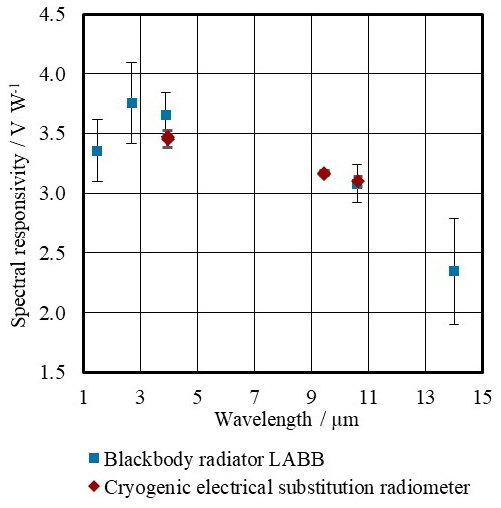
Figure 9Spectral responsivity of the thermopile detector TS-76 measured with the cryogenic electrical substitution radiometer (red) and at the blackbody radiator LABB (blue). The results are consistent within the given combined measurement uncertainty. The uncertainty bars in the diagram represent standard uncertainties.
A systematic difference between both calibration approaches has to be noted: the sensitive area of the detector is fully irradiated within the aperture area at the LABB but only at its centre when using laser radiation at the cryogenic electrical substitution radiometer. Therefore, inhomogeneities of the spectral responsivity over the sensitive area lead to a systematic difference in the calibration results between the two different approaches. The known slight increase of about 5 % of the spectral responsivity in the edges of the sensitive area of the thermopile detector TS-76 leads to a systematically higher result for the spectral responsivity of about 2 % at the LABB. The data depicted in Fig. 9 are not corrected for this effect.
5.2 Measurement uncertainty budget
Table 1 lists all input quantities Xi including their estimated values xi and standard uncertainties u(xi) for an exemplary measurement at 10.6 µm. All these uncertainty contributions lead to a combined standard measurement uncertainty uc of the detector responsivity of about 5.1 % in this case.
The uncertainty u(TLABB) of the temperature of the LABB is estimated to be 500 mK. The actual blackbody temperature can be measured close to the bottom of the cavity according to the ITS-90 using the SPRTs with an uncertainty of only several millikelvin (Taubert, 2003), and the standard deviation of the measured temperature during one calibration cycle is likewise low. But the conservative approximation of the temperature uncertainty also respects radial and axial temperature inhomogeneity of the heat pipes and misalignment of the optical components and the detector in front of the LABB. Nevertheless, the LABB temperature uncertainty can be neglected with respect to the overall measurement uncertainty of the calibration. The same counts for the impact of the geometry uncertainty, the emissivity uncertainty, the detector noise and the uncertainty of the refractive index of air.
In contrast, the measurement of the filter transmittances both in the bandpass and the out-of-bandpass spectral ranges causes dominating uncertainty contributions. Hence, the individual uncertainty of the calibration varies almost only with the applied bandpass filters due to their individual spectral transmittance and attenuation. Especially, the spectral location of their bandpass wavelength with respect to the spectral distribution of the thermal radiation of the LABB given by Planck's law is crucial.
Table 2Reached relative standard measurement uncertainties for the wavelengths which have been realized for detector calibrations at the blackbody radiator LABB by using characterized bandpass filters.

This spectral irradiance at a blackbody temperature of 1200 K has its maximum in the wavelength range at about 2.5 µm and decreases at longer wavelengths (Fig. 3). Hence, the radiant power in the filter bandpass drops down at longer calibration wavelengths, and at the same time the amount of radiant power that has to be blocked increases significantly. Therefore, the uncertainty contribution of the filter attenuation increases significantly at longer wavelengths. For this reason, the measurement uncertainty at 14 µm increases to 19 %, whereas it is about 5 % at 3.9 µm. The uncertainty of the measurement at longer wavelengths can be improved by using filters with a broader bandpass range to maximize the amount of available radiant power. Furthermore, the attenuation is improved by using two bandpass filters instead of a single filter.
The uncertainty of the correction of the air absorption, which is based on HITRAN data (Rothmann et al., 2013), was conservatively estimated as the correction itself and is not dominating the overall measurement uncertainty for wavelengths outside absorption bands. But at the calibration wavelength of 2.7 µm, which is in a spectral region with atmospheric absorption, the combined measurement uncertainty increases to about 9 % for this reason.
An additional approach for the SI-traceable calibration of detectors regarding their spectral responsivity in the NIR and MIR was realized at PTB by using the calculable radiation of a large-area blackbody called LABB operated at about 1200 K with a precision aperture and optical bandpass filters. The transmittance of the filters was accurately characterized with a Fourier transform spectrometer, and the detectors under calibration are thereby irradiated by a calculable spectral radiant power.
A comprehensive measurement uncertainty budget was developed which especially handles the transmission of the optical filters by using a suitable mathematical model for the filter transmittance.
Thermopile detectors of the type TS-76 were calibrated in terms of their spectral responsivity with several bandpass filters in the spectral range from 1.5 µm up to 14 µm. The combined measurement uncertainty is in the range between 5 % and 19 % (see Table 2), and the measurements are consistent with previous calibrations at PTB's national primary detector standards.
By this means, this measurement procedure was established as an additional SI-traceable calibration approach for detectors in the NIR and MIR. The calibration using blackbody radiation offers the possibility for calibrations at wavelengths where characterized bandpass filters are available. This is especially of interest for wavelengths where currently no laser radiation sources are available at PTB's cryogenic electrical substitution radiometer facility.
It is planned to calibrate further types of MIR transfer standards such as pyroelectric detectors at the LABB in terms of their spectral responsivity to show the applicability of this method. These calibrated transfer detectors, which are typically calibrated with high effort and lowest possible uncertainty against PTB's national cryogenic radiometer standard, are used as transfer standard detectors for the calibration of customer detectors. For this application, the PTB is installing a detector comparator facility for routine customer calibrations in the NIR and MIR. This facility will use laser radiation sources to calibrate detectors at specific wavelengths and a thermal, broadband radiation source in combination with a monochromator setup to calibrate detectors at any wavelength by using an interpolation of the spectral responsivity of the transfer standards. However, if lowest possible uncertainties are not needed, customer detectors may also be simply calibrated using the blackbody radiator.
All relevant measurement results are shown in the publication. However, the underlying measurement data are not publicly available but can be requested from the authors, if required.
TP, PM, LW, UJ, CM, DT and JH worked together on the development and realization of the measurement approach, data evaluation and interpretation. TP performed the calibration measurements at the LABB; CM and DT contributed to the characterization measurements of the filters. TP, PM and LW developed the mathematical approach for the uncertainty contribution of the filter transmittance measurement and wrote the article with contributions from all the authors.
The authors declare that they have no conflict of interest.
The component producers and suppliers are mentioned for identification purposes only. Such identification does not imply recommendation or endorsement by the PTB nor does it imply that the producers or suppliers identified are necessarily the best available for the purpose.
Significant technical support by Elzbieta Kosubek, and Philipp Tesch for the filter transmittance measurement at the spectral comparator facility and by Marco Schulz and Klaus Anhalt for the operation of the blackbody radiator LABB is gratefully acknowledged.
This open-access publication was funded by the Physikalisch-Technische Bundesanstalt.
This paper was edited by Klaus-Dieter Sommer and reviewed by two anonymous referees.
Allison, R. S., Johnston, J. M., Craig, G., and Jennings, S.: Airborne Optical and Thermal Remote Sensing for Wildfire Detection and Monitoring, Sensors (Basel) 16, 1310, https://doi.org/10.3390/s16081310, 2016.
BIPM – Bureau International des Poids et Mesures: Evaluation of measurement data – Guide to the expression of uncertainty in measurement (GUM), Joint Committee for Guides in Metrology, JCGM 100:2008, available at: https://www.bipm.org/en/publications/guides (last access: 15 April 2021), 1995.
Bönsch, G. and Potulski, E.: Measurement of the refractive index of air and comparison with modified Edlen's formulae, Metrologia, 35, 133–139, 1998.
Hartmann, J., Hollandt, J., Meindl, P., Taubert, D., and Werner, L.: Traceable radiometric calibration of semiconductor detectors and their application for thermodynamic temperature measurement, MAPAN J. Metrol. Soc. India, 25, 3–10, https://doi.org/10.1007/s12647-010-0003-0, 2010.
Kohlrausch, F.: Praktische Physik, in: Volume 1–3, Edition 24, B. G. Teubner, Stuttgart, 1996.
Martin, J. E., Fox, N. P., and Key, P. J.: A Cryogenic Radiometer for Absolute Radiometric Measurements, Metrologia, 21, 147–155, 1985.
Noulkow, N., Taubert, R. D., Meindl, P., and Hollandt, J.: Infrared Filter Radiometers for Thermodynamic Temperature Determination below 660 ∘C, Int. J. Thermophys., 30, 131–143, https://doi.org/10.1007/s10765-008-0458-1, 2009.
Pohl, T.: Entwicklung und Charakterisierung eines Transfernormals für die Messung optischer Strahlungsleistung im infraroten Spektralbereich auf Grundlage eines Thermosäulendetektors, MS thesis, TU Berlin, Berlin, 2018.
Pohl, T., Meindl, P., Johannsen, U., Taubert, D., and Werner, L.: Measurement of the absolute spectral responsivity in the mid-infrared based on the cryogenic electrical substitution radiometer and an optimized thermopile detector, J. Sens. Sens. Syst., 8, 195–205, https://doi.org/10.5194/jsss-8-195-2019, 2019.
Rothman, L. S., Gordon, I. E., Babikov, Y., Barbe, A., Benner, D. C., Bernath, P. F., Birk, M., Bizzocchi, L., Boudon, V., Brown, L. R., Campargue, A., Chance, K., Coudert, L., Devi, V. M., Drouin, B. J, Fayt, A., Flaud, J.-M., Gamache, R. R. Harrison, J., Hartmann, J.-M., Hill, C., Hodges, J. T., Jacquemart, D., Jolly, A., Lamouroux, J., LeRoy, R. J., Li, G., Long, D., Mackie, C. J., Massie, S. T., Mikhailenko, S., Müller, H. S. P., Naumenko, O. V., Nikitin, A. V., Orphal, J., Perevalov, V., Perrin, A., Polovtseva, E. R., Richard, C., Smith, M. A. H., Starikova, E., Sung, K., Tashkun, S., Tennyson, J., Toon, G. C., Tyuterev, V. G., Auera, J. V., and Wagner, G.: The HITRAN 2012 Molecular Spectroscopic Database, J. Quant. Spectrosc. Ra., 130, 4–50, https://doi.org/10.1016/j.jqsrt.2013.07.002, 2013
Sobrino, J. A., Del Frate, F., Drusch, M., Jiménez-Muñoz, J. C., Manunta, P., and Regan, A.: Review of Thermal Infrared Applications and Requirements for Future High-Resolution Sensors, IEEE T. Geosci. Remote, 54, 2963–2972, https://doi.org/10.1109/TGRS.2015.2509179, 2016.
Taubert, D. R.: Radiometrische Messung thermodynamischer Temperaturen und Vergleich mit der Internationalen Temperaturskala (ITS-90) im Bereich von 419 ∘C bis 660 ∘C, Dissertation, Berlin, 2003.
Taubert, R. D., Meindl, P., Monte, C., Werner, L., Pohl, T., and Hollandt, J.: Absolute Mid-infrared Spectral Responsivity Scale Based on Thermal Detectors and the Cryogenic Radiometer, in: AMA-Konferenz SENSOR/IRS2, 30 May–1 June 2017, Nürnberg, Germany, 2017.
- Abstract
- Introduction
- Concept of the calibration of the spectral responsivity using calculable blackbody radiation
- Calculation of the spectral responsivity
- Calculation of the combined measurement uncertainty
- Calibration of the spectral responsivity of thermopile detectors at the LABB
- Summary and outlook
- Data availability
- Author contributions
- Competing interests
- Disclaimer
- Acknowledgements
- Financial support
- Review statement
- References