the Creative Commons Attribution 4.0 License.
the Creative Commons Attribution 4.0 License.
 | 15 Jun 2021
Assessment of uncertainties for measurements of total near-normal emissivity of low-emissivity foils with an industrial emissometer
Jacques Hameury
Guillaume Failleau
Mariacarla Arduini
Jochen Manara
Elena Kononogova
Albert Adibekyan
Christian Monte
Alexander Kirmes
Eric Palacio
Holger Simon
The TIR100-2 emissometer (manufactured by Inglas GmbH & Co.KG) is an emissivity measurement device used by several producers of thermal insulation products for buildings and by some organizations certifying performance of insulation products. A comparison of emissivity measurements on low-emissivity foils involving different measurement techniques, including the TIR100-2 emissometer, gave widely dispersed results; the discrepancies were not explained. The metrological performance of the TIR100-2 emissometer and the uncertainties for measurement on reflective foils was not known, which could be detrimental to users. In order to quantify the performance of TIR100-2 devices for measurement of total near-normal emissivity of low-emissivity foils, the Laboratoire National de Métrologie et d'Essais (LNE) analyzed in detail the measuring principle and listed the associated assumptions and uncertainty sources. A TIR100-2 emissometer actually measures the reflectance and, for opaque materials, the emissivity is calculated from the measured reflectance. The parameters analyzed experimentally are the temperature stability and uniformity of the thermal radiation source, the emissivity of the radiation source, the response function linearity and the spectral sensitivity of the radiometric detection system measuring the reflected radiation, the size of the measurement area, and the measurement repeatability and reproducibility. A detailed uncertainty budget was established. The uncertainty sources taken into account are the uncertainties of the emissivities of the two calibrated standards used for calibration, the stability and uniformity of the radiation source temperature, the non-linearity and the spectral sensitivity of the radiometric detection system, the specific measurement condition related to the radiation source temperature, the uncertainties related to the temperatures of the standards and the sample, the noises on results, and the non-homogeneity in emissivity of the tested material. The combined measurement uncertainty was calculated for different types of reflective foils; the expanded uncertainty is around 0.03 for total near-normal emissivity measurements on smooth low-emissivity foils. A measurement campaign on five types of low-emissivity foils, involving four TIR100-2 emissometers, and a comparison to a primary reference setup at the Physikalisch-Technische Bundesanstalt (PTB) confirmed the uncertainties assessed.
- Article
(2468 KB) - Full-text XML
- BibTeX
- EndNote


Low-emissivity surfaces are sometimes used in association with thin air or vacuum space to create resistance to heat transfer. Some insulation products manufactured for building thermal insulation use this principle to increase the thermal resistance of a thermal insulation system without using more insulation material. Standard ISO 6946:2017 gives the calculation method for calculating the thermal resistance of an air space considering the emissivities of the surfaces limiting the air space (ISO, 2017). To be in conformity with the European Directive 2010/31/EU on the energy performance of buildings, manufacturers of insulation products using the low-emissivity effect must declare the values of emissivity for their products (European Commission, 2010). A standard was developed, through the working group CEN/TC89/WG12, by the European Committee for Standardization (CEN) for the determination of the declared thermal performance of insulation products that rely upon their low-emissivity surfaces to provide a portion of their claimed thermal performance. The standard EN 16012+A1 defines, among other things, the methods for measuring the emissivities of low-emissivity thermal insulation products (CEN, 2015). The methods recommended are the integrating sphere and a hemispherical near-normal reflectometer. The integrating sphere associated with a Fourier transform infrared spectrometer is a quite expensive technique and requires expertise and an appropriate optical configuration to make correct measurements (Blake et al., 2018; Clarke and Compton, 1986). Most non-specialist users prefer the solution of a hemispherical near-normal reflectometer such as the TIR100-2 emissometer manufactured by Inglas GmbH & Co.KG in Germany (Inglas, 2020).
A comparison of the emissivity measurement techniques mainly used by industry and organization testing and certifying thermal insulation products was organized in 2013 by CEN/TC89/WG12 to check the performance of the existing measurement techniques. The TIR100-2 emissometer and integrating spheres associated with Fourier transform spectrometers were involved in the comparison. The comparison gave very scattered results, with a dispersion up to 0.06 for a mean measured emissivity of 0.05 on a reflective foil (CEN/TC89/WG12, 2013). No explanation was found for the discrepancies between results; the performances of the techniques were not known precisely at that time when applied to low-emissivity foils. At the request of the working group CEN/TC89/WG12, the research project EMIRIM “Improvement of Emissivity Measurements on Reflective Insulation Materials” was carried out to improve the measurements of total hemispherical emissivity on the low-emissivity foils found as external surfaces on some thermal insulation products for buildings (JRP EMIRIM, 2017). One of the project's technical tasks was the detailed characterization of the metrological performance of TIR100-2 emissometers. TIR100-2 was known at the beginning of the project as a device allowing fast measurements of total near-normal emissivity and having a good fidelity among several devices. However, the performance in terms of trueness and uncertainty was not known when used for low-emissivity foils. Four partners in the EMIRIM project used TIR100-2 devices; two of them were lent by Inglas to two metrological institutes for performance characterizations.
In the EMIRIM project, the Physikalisch-Technische Bundesanstalt (PTB) performed a detailed analysis of the measurement field size of a TIR100-2 device, tested the effect of using different sets of standards for calibration and compared the results to results from the primary emissivity measurement setup EMAF at the PTB (Kononogova et al., 2019). The PTB did not establish a detail uncertainty budget for the TIR100-2 device applied to low-emissivity foils.
In the study presented here, LNE (Laboratoire National de Métrologie et d'Essais) characterized in detail a TIR100-2 device with the objective of establishing an uncertainty budget for measurement of total near-normal emissivity on low-emissivity foils. The measurement results were compared to results from the primary setup EMAF at the PTB (Monte and Hollandt, 2010) for global validation of the results including the uncertainties.
The parameter actually required for calculation of radiation heat transfers between surfaces limiting an air space is the total hemispherical emissivity of the surfaces. The parameter measured with the TIR100-2 emissometers is the total near-normal emissivity, which is the emissivity for all wavelengths along a direction close to the surface normal. The characterizations, results, and conclusions presented in this publication concern only the measurement of total near-normal emissivity. The calculation of total hemispherical emissivity from the total near-normal emissivity result is beyond the scope of this publication.
The parameter actually measured with a TIR100-2 device is the total hemispherical near-normal reflectance. The measuring principle is based on the relation (Eq. 1) between the total hemispherical near-normal reflectance and the total near-normal emissivity, which is the desired parameter:
where εsamp is the sample total near-normal emissivity, and is the hemispherical near-normal reflectance.
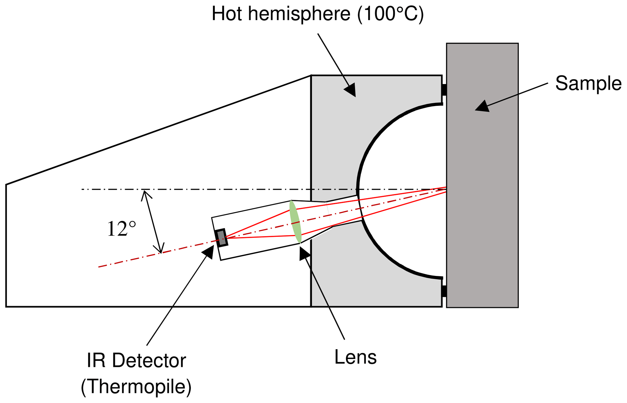
The relation (Eq. 1) is true if the material is opaque, the irradiance on the sample surface is Lambertian, the spectral emissivities of the tested material and of the incident radiation generator are constant depending on wavelength and the spectral sensitivity of the radiometric detection system is constant as a function of wavelength. The conditions for the validity of Eq. (1) are well explained by Siegel and Howell (Siegel and Howell, 1972). For reflectance measurement, the incident radiation on the sample surface is generated by a hemisphere heated at a steady temperature of 100 ∘C. The hemisphere is coated with a high-emissivity black coating. A part of the incident radiation is reflected by the surface of the sample at ambient temperature, and a radiometric infrared detection system collects the reflected radiation through an opening in the hemisphere. The radiometric detection system is constituted by a Fresnel polymer lens and a Dexter-2MC thermopile detector with a potassium bromide (KBr) window 1.01 mm thick (Dexter, 2020). The entrance pupil of the detection system is limited by the opening in the hemisphere. The reflected radiation is collected by the detection system with a mean angle of 12∘ to the normal to the sample surface. The quite low measurement angle allows the hypothesis of equality between the measured total directional emissivity and the total near-normal emissivity. Indeed, for low emissivities, the directional emissivity does not vary significantly with the angle for angles below 25∘ to the normal (Janssen and Lohrengel, 1991; Geotti-Bianchini and Lohrengel, 1989). The radiating cavity has a diameter of 70 mm, and the opening for detection has a diameter of 6.3 mm. For calibration and measurements, the sample surface must be placed in contact with the structure of the instrument so that the surface is in the same plane for calibrations and measurements. During measurements, the sample receives the radiation emitted by the hemisphere and absorbs a part of that radiation, which generates a heating of the sample proportional to the duration of exposition. The measurement model assumes that the temperature of the sample is the same as the temperatures of the two standards used for calibration. In order to limit the heating of the sample and of the standards, the sample and the standards must be put in front of the hemisphere, and the radiometric signal must be measured within a very short time, less than 3 s.
The instrument must be calibrated to set the sensitivity in emissivity; the calibration is done at two levels of emissivity, a very low emissivity and a high emissivity. The instrument is supplied with a working standard made of aluminum and having a low-emissivity mirror-like side and a high-emissivity side with deep parallel ribs coated with a black matt paint.
The model for emissivity calculation implemented in the instrument assumes that the radiometric signal is proportional to the total hemispherical near-normal reflectance of the sample. Equation (2) is used for calculation of the total near-normal emissivity from the radiometric signals (Inglas, 2014):
where εsamp is the total near-normal emissivity of the sample, εH is the total near-normal emissivity of the high-emissivity standard, εN is the total near-normal emissivity of the low-emissivity standard, Vsamp is the radiometric signal measured on the tested sample, VH is the radiometric signal measured during calibration on the high-emissivity standard and VN is the radiometric signal measured during calibration on the low-emissivity standard.
The assumptions associated with the model are the opacity of the tested material, the proportionality of the radiometric signal with the total hemispherical near-normal reflectance of the surface, the sample temperature being the same as the temperature of the standards, the stability and the uniformity of the radiating hemisphere temperature, the uniformity of the total emissivity of the hemisphere, the temperatures of the optical elements constituting the radiometric detection system being steady, the spectral near-normal emissivities of the sample and the standards and the spectral sensitivity of the radiometric detection system being constant as a function of wavelengths.
The assumptions made for establishing the model must be validated and/or the deviations from the assumptions must be quantified in order to assess the uncertainties due to the deviations.

3.1 Stability of the radiating hemisphere temperature
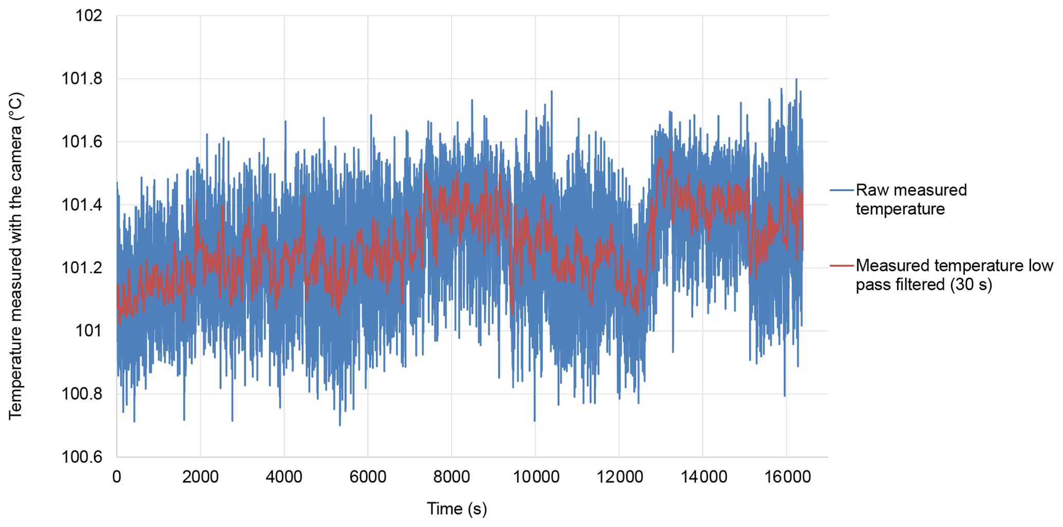
LNE analyzed the stability of the temperature of the hemisphere using an infrared camera (FLIR SC660). The temperature directly measured by the camera is quite noisy. With the emissometer stabilized in temperature, the hemispherical cavity temperature was measured with a frequency of 1 Hz during almost 5 h (Fig. 2). The raw temperature results are affected by a noise characterized by a standard uncertainty of 0.15 K for a sample of 100 results (100 s duration). In normal use, the emissometer is recalibrated every 10 min (Inglas, 2014). When testing low-emissivity foils, after each calibration, a measurement is performed on the low-emissivity standard 30 s after the calibration to ensure that the calibration is reliable. Then the measurements are performed on the samples to be tested every 30 s. The 30 s duration between each measurement is important for letting the device recover from the perturbation caused by the presence of the sample, which changes the heat power lost by the hot hemisphere. For each individual measurement, the operator checks that the hot hemisphere temperature displayed by the emissometer is within a mean value ± 0.25 K. The mean value can depend slightly on the device, but it is set close to 100 ∘C by the manufacturer. Considering the procedures for calibration and measurements with the frequent control of hemisphere temperature by the operator, the raw temperatures of the hot hemisphere measured with the infrared camera were low-pass-filtered by sliding averaging over 30 s duration (Fig. 2). The maximum variations of the measured low-pass-filtered temperature during periods of 600 s (the maximum duration between calibrations) were calculated; the results are shown graphically in Fig. 3. From those results, it is reasonable to account for variations of 0.3 K for the temperature of the hemisphere to assess the related uncertainty on the measured emissivity. The signal measured by the radiation detector of the emissometer is proportional to the sample surface radiance in the direction of measurement. The near-normal radiance of the sample surface when exposed to the radiation from the hemisphere was calculated for the temperatures 100 and 100.3 ∘C as a function of sample emissivity. The difference between the two radiances varies linearly with the sample emissivity, leading to an error maximum for low emissivities (maximum reflection of the hemisphere radiation).
3.2 Uniformity of the radiating hemisphere temperature
The signal delivered by the radiometric system of the TIR100-2 is proportional to the sum of two terms. The first term is the part reflected by the sample surface (measurement spot) toward the radiometric system aperture. This reflected radiation is proportional to the radiation incident on the measurement spot and coming from the hemisphere, that is to say, from all directions. The second term is the radiation emitted by the sample surface (measurement spot) toward the radiometric system aperture. The reflection of the radiation from the hemisphere toward the aperture has a hemispherical directional character, and the emission from the sample surface toward the aperture has a directional character. The temperature and the emissivity of the hemisphere must be uniform for the validity of the measurement model implemented in the emissometer (Eq. 2).
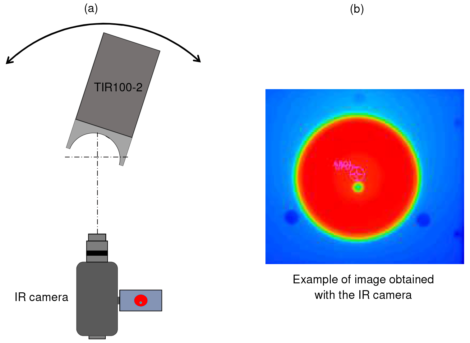
Figure 4Analysis of the temperature uniformity of the heating hemisphere. (a) Experimental configuration. (b) Example of the thermal image obtained.

Figure 5Relative temperature curves obtained in the horizontal and vertical planes containing the center of the hemisphere.
LNE analyzed the temperature uniformity of the hemisphere using the same infrared camera that was used for measuring the temperature stability. The TIR100-2 emissometer was placed on a two-axis goniometer in order to rotate the emissometer around the center of the hemisphere. Having the rotation of the TIR100-2 around the center of the hemisphere, the measurement of the temperature of the spot is always done along a direction locally perpendicular to the hemisphere. The experimental configuration is illustrated in Fig. 4. A spot is defined on the image, and the mean temperature over the spot is calculated: this mean temperature is considered a local temperature of the hemisphere. The rotation of the TIR100-2 around the two perpendicular axes gave the relative temperature curves given in Fig. 5. The summit of the hemisphere was defined as the reference point.
The direction for reflectance measurement is 12∘ to the normal to the sample surface. The TIR100-2 is calibrated with a solid specular sample, so in low-emissivity calibration configuration only a specific region of the hemisphere generates the radiation reflected by the specular standard and measured by the instrument. The precise location of the region implied is not easy to know because the geometry of the beam collected by the radiometric system is poorly defined. When comparing a more or less specular sample to a perfectly specular sample, the possible variation of the mean temperature of the hemisphere region generating the measured radiation is assumed to be within ± 1.0 K.
3.3 Emissivity of the coating applied to the radiating hemisphere
Knowledge of the total emissivity of the hemisphere is required to quantify the multi-reflection effects in the cavity constituted by the hemisphere and the sample surface. It is preferable that the emissivity of the hemisphere is high and does not show strong spectral variations.
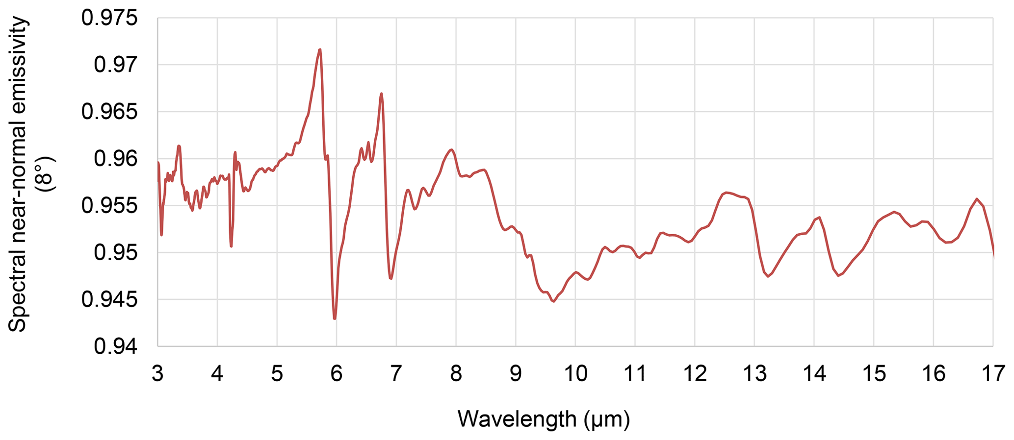
LNE measured the near-normal spectral emissivity on a sample of the coating provided by Inglas. The measurement was performed with a Φ 75 mm integrating sphere from LNE by reference to an Infragold® working standard; the sample was at room temperature. The spectral near-normal emissivity curve is given in Fig. 6. The total near-normal emissivity of the coating was calculated using Eq. (3).
where λ is the wavelength, ελ is the spectral near-normal emissivity, T is the coating temperature in use (100 ∘C), and is the spectral radiance of a blackbody for the temperature T and the wavelength λ. For the spectral range 3 to 17 µm, the spectral near-normal emissivity is the measured emissivity. For wavelength from 17 to 50 µm, the spectral emissivity is assumed constant and equal to the mean of the spectral emissivities measured from 16 to 17 µm. The total hemispherical emissivity was calculated from the total near-normal emissivity using a model recommended for high emissivities (Rubin et al., 1987). For the quantification of the uncertainty on the total hemispherical emissivity of the coating, the uncertainties taken into account are the uncertainties of the measured spectral emissivities between 3 and 17 µm, the uncertainties on the spectral emissivities extrapolated above 17 µm and an uncertainty related to the model of calculation. The expanded uncertainty for the extrapolated spectral emissivities is assumed to increase linearly with wavelength from 0.02 at 17 µm to 0.25 at 50 µm. The expanded uncertainty related to the model of calculation is 0.02 (k=2). The total hemispherical emissivity of the coating calculated from the spectral results is 0.91 ± 0.03 (k=2) for the temperature 100 ∘C.
3.4 Response linearity of the radiometric detection system
The model of response implemented in the emissometer (Eq. 2) is based on the linear response assumption as a function of the apparent total radiance of the sample surface.
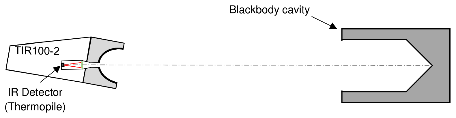
Figure 7Experimental configuration for testing the linearity of response of the radiometric detection system of a TIR100-2 emissometer.
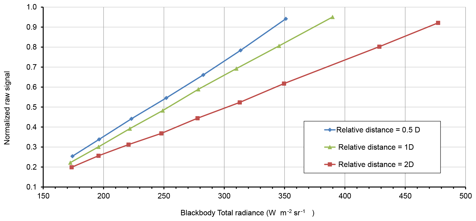
Figure 8Normalized raw signal measured by the TIR100-2 as a function of the total radiance of the blackbody for three distances between the emissometer and the blackbody aperture.
A tentative experiment was carried out by LNE to test the global linearity of the response of a TIR100-2 emissometer. The experimental configuration is shown in Fig. 7. The emissometer was tilted at 12∘ so that the axis of the radiometric detection system is horizontal. The emissometer was placed at a distance from a blackbody source with adjustable temperature, and the detection system axis was aligned with the blackbody axis. The blackbody is a Gemini R 550 portable blackbody calibration source from Isotech. The cavity is cylindrical with a conical bottom (diameter 65 mm, depth 180 mm). The apparent emissivity of the cavity is 0.995 (Isotech, 2021). The temperature of the cavity was measured with a calibrated RTD sensor. The blackbody was placed successively at three different distances from the emissometer and for each distance; the temperature of the blackbody was changed so that the signal delivered by the emissometer covers almost all the signal range when measuring emissivities from zero to one. The normalized raw signal 1 corresponds to the signal measured for a very low emissivity. The blackbody temperature was changed, respectively, from 28.5 to 100.3 ∘C, 24.8 to 110.2 ∘C and 24.1 to 130.1 ∘C, respectively, for the distances 0.5 D, 1 D and 2 D from the center of the heating hemisphere to the opening of the blackbody. D was 70 mm, the diameter of the hemisphere. These tests showed that the response of the radiometric detection system is as a first approximation linear as a function of the total irradiation on the optical system aperture. However, the tests are sensitive to various perturbations such as the variations of atmospheric transmittance along the optical path and the variable heating of the lens with the irradiance on the aperture. When the raw measured signal is quite high (as when the sample emissivity is less than 0.2), the tests showed that the sensitivity of the radiometric detection system can be considered constant within 0.3 %.
3.5 Determination of the relative spectral response of the TIR100-2
Knowledge of the radiometric system spectral sensitivity is required for quantifying the potential error due to the imperfectly flat spectral response in the spectral range 3 to 50 µm. The TIR100-2 spectral response is mainly related to the spectral sensitivity of the detector and to the spectral transmittance of the lens used for focusing the radiation on the detector. For quantification of the errors related to the specific spectral response, knowledge of the relative spectral sensitivity (spectral sensitivity divided by the maximum spectral sensitivity) is sufficient. Knowledge of the absolute spectral sensitivity is not required.
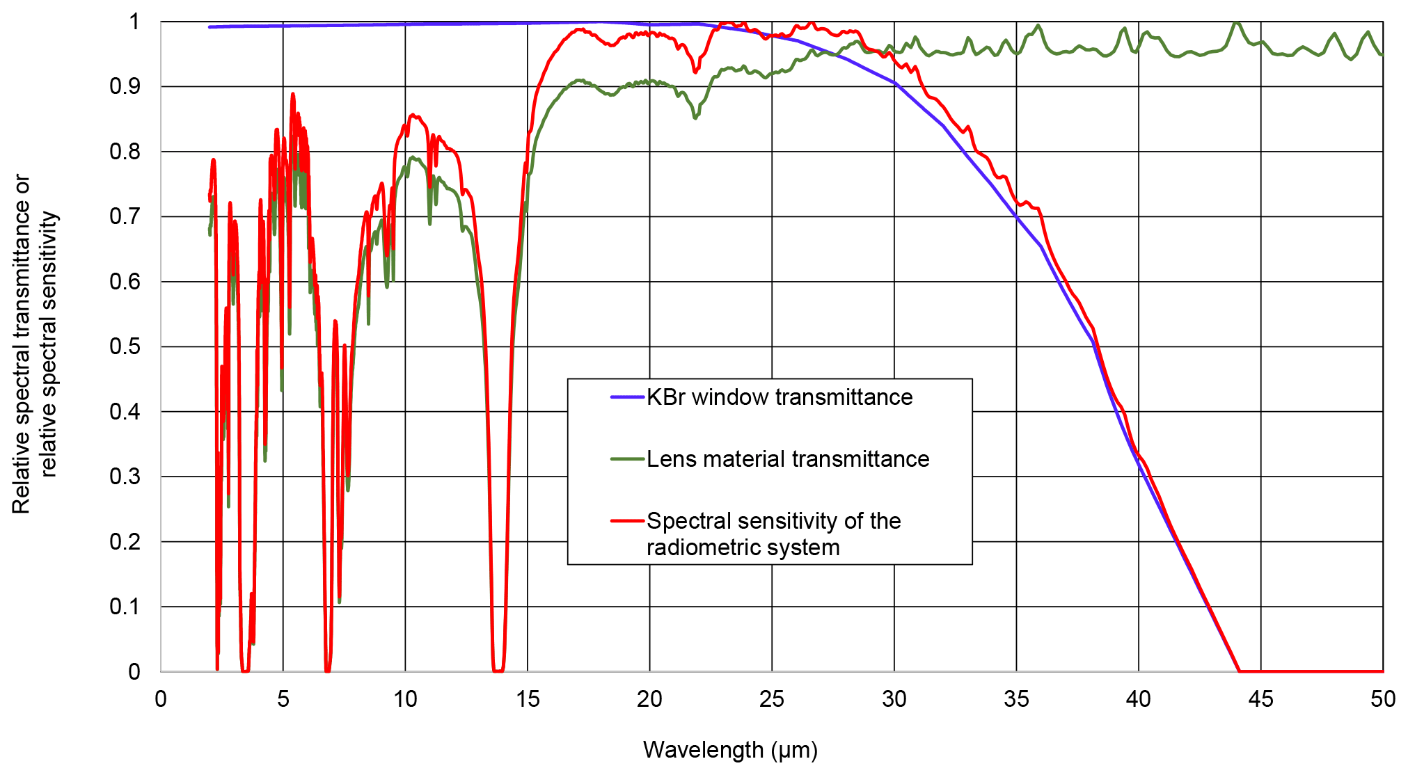
Figure 9Relative spectral transmittance of the KBR window of the detector, relative spectral transmittance of the lens material and relative spectral sensitivity of the radiometric detection system of the TIR100-2 emissometer.
The transmittance of the lens material was measured by LNE from 2 to 50 µm using a FTIR spectrometer on a sample supplied by Inglas. The measurement was done on a sample with a thin uniform layer of the material used for the lens. The tested area was 0.37 mm thick with a constant thickness. The lens used in the TIR100-2 is a Fresnel lens with a maximum thickness of 0.47 mm. The relative spectral transmittance curve obtained by measurement is shown in Fig. 9.
The relative spectral sensitivity of TIR100-2 instruments is mainly generated by the product of the relative spectral transmittance of the lens by the relative spectral transmittance of the detector window. The detector used is a Dexter-2MC thermopile with a KBR window 1.02 mm thick. Dexter company claims that the detector without a window has a flat spectral response from 100 nm to 100 µm and has a linear signal output for irradiance from 10−6 to 0.1 W cm−2 and that the KBR window has a band pass from 0.2 to 30 µm (Dexter, 2020). The relative regular spectral transmittance of a 1.02 mm-thick KBR window was calculated using the spectral refractive index and the absorption coefficient of KBR material (Driscoll and Vaughan, 1978). The relative spectral sensitivity of the radiometric system was calculated as the product of the relative lens material transmittance by the relative spectral transmittance of the KBR window. The spectral relative curves are shown in Fig. 9. The relative spectral sensitivity is mainly influenced by the spectral transmittance of the lens material for wavelengths below 25 µm and by the spectral transmittance of the KBR window for wavelengths above 25 µm.
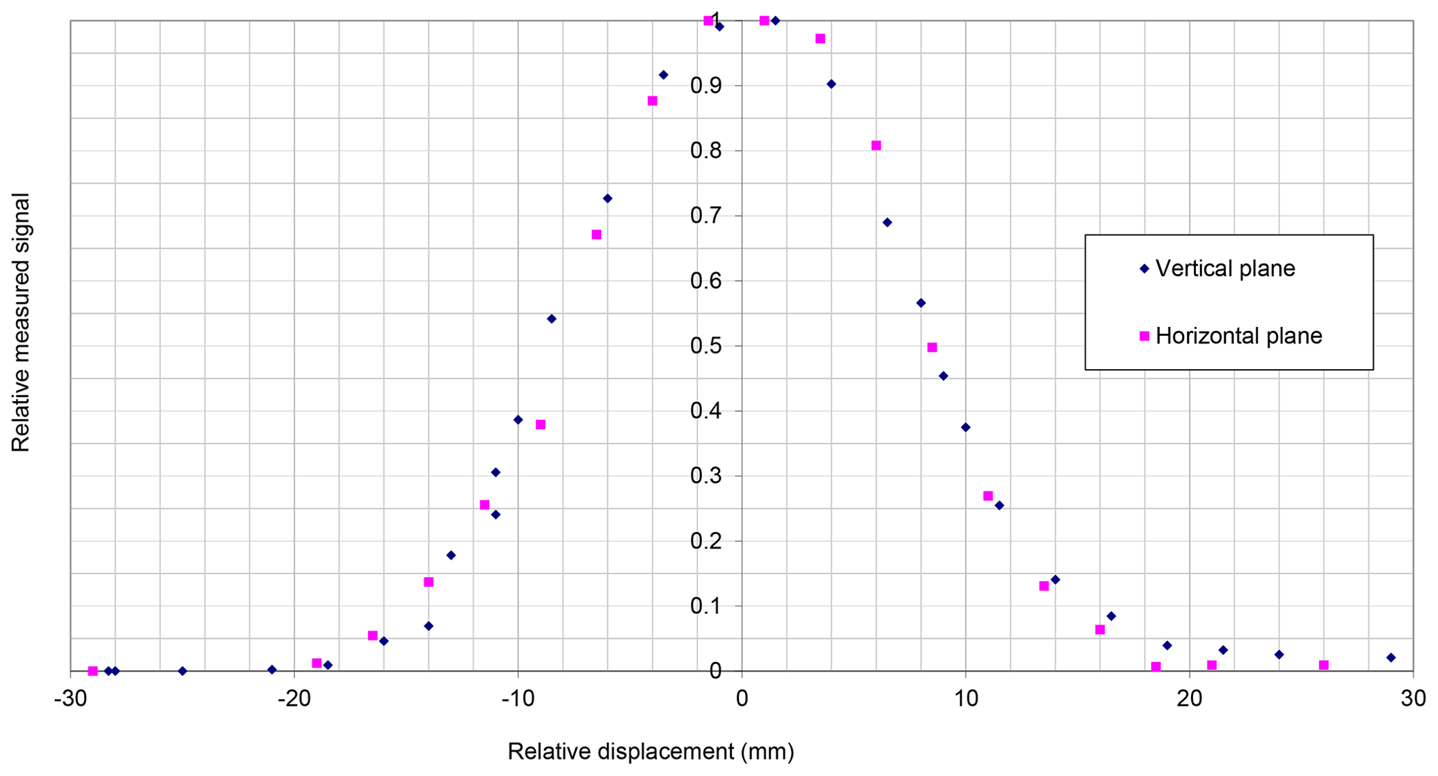
Figure 10Relative spectral signal measured with the TIR100-2 emissometer when displacing a reflective strip in the plane of the sample surface.
3.6 Size of the measurement field
LNE measured the measurement field size by linear displacement of a reflective strip 16 mm wide with parallel edges in the plane of the sample surface. The reflective strip was bonded onto a black surface to create a contrast of reflection. The displacement was done along two perpendicular directions, and the curves of the relative variations of signals with displacement are shown in Fig. 10. From the curves and the width of the reflective strip, it is possible to conclude that the overall spot diameter, at the base, is 20 mm, and the spot is quite symmetrical. Kononogova et al. (2019) characterized also in detail the spot size of another TIR100-2 emissometer. They measured the same dimensions of the field seen by the radiometric detection system and showed that 50 % of the radiation collected by the detector comes from a circular area with a diameter of approximately 10 mm. The measurement field dimensions are not a critical parameter, but it can be useful to analyze emissivity results on non-uniform surfaces.
4.1 Uncertainty sources
An exhaustive analysis of the measurement principle, the instrument configuration and the calibration and measurement procedures made it possible to list the uncertainty sources for the measurement of total near-normal emissivity. The uncertainty sources are given below; they are classified according to their origin.
4.1.1 Uncertainty sources related to the TIR100-2 emissometer
The uncertainty sources related to the emissometer are the thermal stability of the TIR100-2 after calibration, the temperature uniformity of the hemisphere, the response non-linearity as a function of sample reflectance, the non-flat spectral response of the radiometric detection system, the hemisphere temperature and the instrument sensitivity to the angular diffusion of reflection on the sample surface.
4.1.2 Uncertainty sources related to the calibration and measurement procedures
The uncertainty sources related to the calibration and measurement procedures are the uncertainties on the total near-normal emissivities of the reference standards used for calibration, the uncertainties related to the temperatures of the reference samples and to the temperature of the tested sample, the measurement noises, and the homogeneity in emissivity of the tested material.
4.2 Evaluation of uncertainties
4.2.1 Uncertainty related to the temperature stability of the radiating hemisphere
It was shown experimentally that the stability of the hemisphere temperature is within 0.3 K between successive calibrations (600 s). Assuming the hemisphere radiates like a blackbody, the apparent total radiance of the sample surface in the direction of measurement is given by Eq. (4).
where εmeas is the total near-normal emissivity measured on the sample, σ is the Stefan–Boltzmann constant (5.670374 × 10⁻⁸ ), Them is the hemisphere temperature and Tsample is the sample temperature.
The magnitude of the error induced by a variation of the hemisphere temperature is given by Eq. (5).
where ΔThem is the variation of the hemisphere temperature (0.3 K).
The standard uncertainty related to the variation of the hemisphere temperature from 100 to 100.3 ∘C is given by Eq. (6).
4.2.2 Uncertainty due to the non-uniformity of the temperature of the radiating hemisphere
The analysis of the uniformity of the hemisphere temperature showed that the non-uniformity that can be considered for quantifying the related uncertainty is ± 1.0 K. The calculation of the potential error related to the non-uniformity was done in the same way as for the non-stability of the hemisphere temperature by using Eq. (5) but considering that ΔThem is the non-uniformity of the hemisphere temperature. Eventually, Eq. (7) gives the standard uncertainty on the measured emissivity related to the non-uniformity.
This quantification of the uncertainty due to the non-uniformity of the hemisphere temperature is quite rough. Indeed, a detailed directional modeling of the multi-reflections between the sample surface and the hemisphere would be more representative of the reality. However, this modeling would require the BRDF (bidirectional reflectance distribution function) of the sample surface and of the hemisphere, and no reliable data are available for those BDRDFs. This paper focuses on the measurements of total near-normal emissivity of very reflective foils. It is then assumed that the potential problem with the hemisphere temperature non-uniformity is the fact that when the sample is tested, the area of the hemisphere “seen” by the radiometric detection system through the reflection on the sample is slightly different from the one seen when the low-emissivity standard (a mirror) is used. The hemisphere temperature non-uniformity around the area seen by the detector when a mirror is tested seems appropriate for quantifying the uncertainty when testing very reflective but not perfectly specular materials.
4.2.3 Uncertainty due to the response non-linearity as a function of reflectance of the sample
A non-linear response is generated by the multi-reflections in the cavity formed by the hemisphere and the sample surface and by the potential non-linearity of the radiometric response of the infrared detector.
The TIR100-2 is calibrated with two reference samples, one with high emissivity and the other one with low emissivity. The emissivity of the hemisphere is below one, so multi-reflections always occur in the cavity, and an error on the measured emissivity is generated by those multi-reflections when the sample has an emissivity different from the emissivity of one of the two standards.
A radiosity model (Siegel and Howell, 1972) was used to calculate the radiosity of the sample placed in front of the hemisphere, and then the error on the measured emissivity was calculated. The radiosity modeling allows the global calculation of multi-reflections assuming that the surfaces are Lambertian (they emit and reflect radiation in a perfectly diffuse manner) and are perfectly grey (radiative properties constant as a function of wavelength).
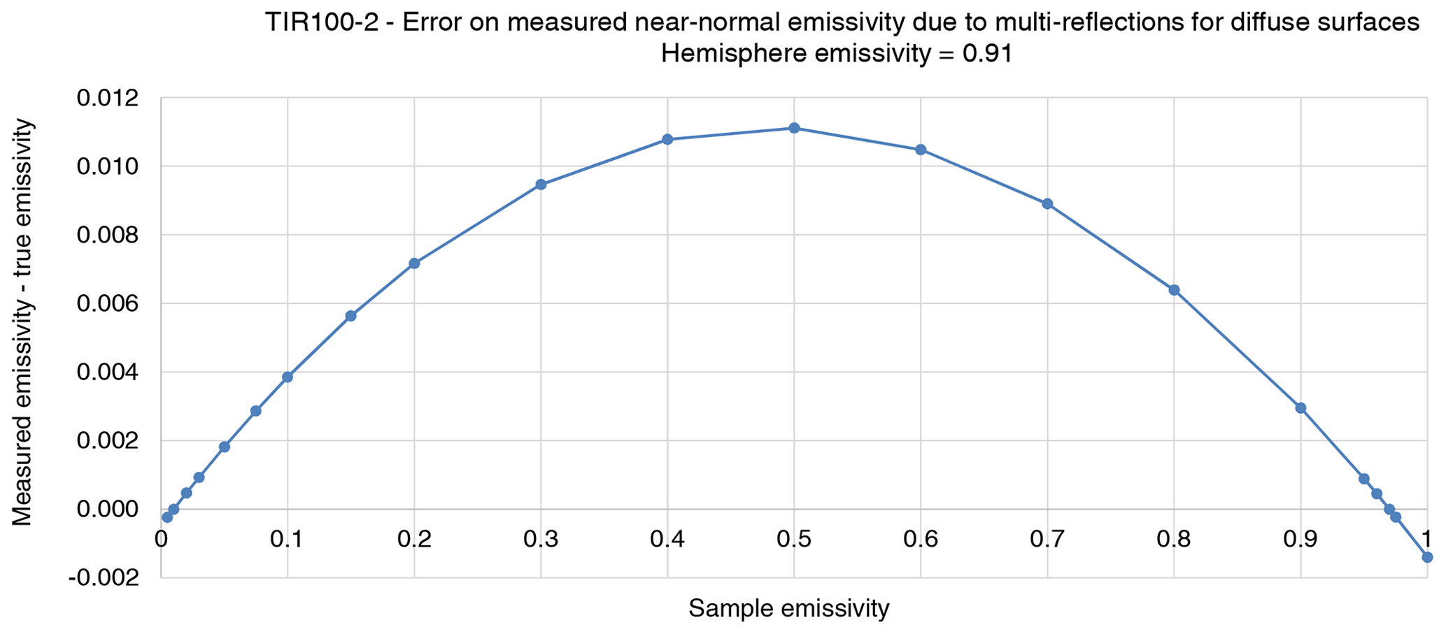
Figure 11Error on the measured total near-normal emissivity due to multi-reflections between the sample surface and the hemisphere.
The error on the measured emissivity was calculated using the radiosity technique, considering that the instrument is calibrated at the two emissivity levels 0.01 and 0.97; the results are shown graphically in Fig. 11. The error is well approximated by Eq. (8).
The quantification of the error due to multi-reflections is based on the quite rough radiosity model. Therefore, no correction is done for multi-reflections on the measurement result, and Eq. (9) gives the standard uncertainty due to multi-reflections.
Assuming that the hemisphere emissivity is one, that the low-emissivity standard has a reflectance of one and that the high-emissivity standard has an emissivity of one, the reflectance of the sample is given at a first-order approximation by Eq. (10).
The relative expanded uncertainty on the ratio of signals being 0.003, the standard uncertainty related to the linearity of response of the radiometric detection system is given by Eq. (11), for emissivities below 0.2.
4.2.4 Uncertainty due to the spectral response of the instrument and due to the hemisphere temperature
The total near-normal emissivity measured on the reflective foils should be the one given by Eq. (12), which is the usual definition of the total near-normal emissivity (Siegel and Howell, 1972).
For calculations of the thermal resistances of building envelopes, the total emissivities of reflective foils must be calculated using a temperature Tsamp around room temperature.
The “total near-normal emissivity” measured by the TIR100-2 emissometer is influenced by the temperature of the radiation source (the hemisphere) and by the spectral sensitivity of the radiometric detection system. The error on the measured total near-normal emissivity was calculated by modeling the three signals needed for a measurement (low-emissivity standard signal, high-emissivity standard signal and sample signal) taking into account the actual relative spectral sensitivity and the temperature of the radiation source.
Signal modeling
The signal measured on the low-emissivity standard is given by Eq. (13).
where is the spectral radiance of a blackbody at the temperature T for the wavelength λ, sensTIR(λ) is the relative spectral sensitivity of the radiometric detection system, Them is the hemisphere temperature, Tsamp is the temperature of the sample or of the standard when calibrating and εN is the total near-normal emissivity of the low-emissivity calibrated standard.
Equation (14) gives the signal measured on the high-emissivity standard.
where εH is the total near-normal emissivity of the high-emissivity calibrated standard.
The signal measured on the tested sample is given by Eq. (15).
where ελ is the spectral near-normal emissivity of the sample.
Equation (16) gives the error on the total near-normal emissivity measured by the TIR100-2 instrument due to the spectral sensitivity and due to the specific conditions of measurement (hemisphere temperature).
The spectral range for the definition of the total near-normal emissivity (Eq. 12) and for the calculations of signals (Eqs. 14–16) was limited from 3 to 50 µm. This spectral range is appropriate, because for a grey body (a body with constant spectral emissivity), 98.2 % and 96.7 % of the total radiation are emitted in that spectral range when the body is at 100 and 20 ∘C, respectively. Furthermore, the spectral sensitivity of the emissometer is zero for wavelengths above 44 µm (Fig. 9).
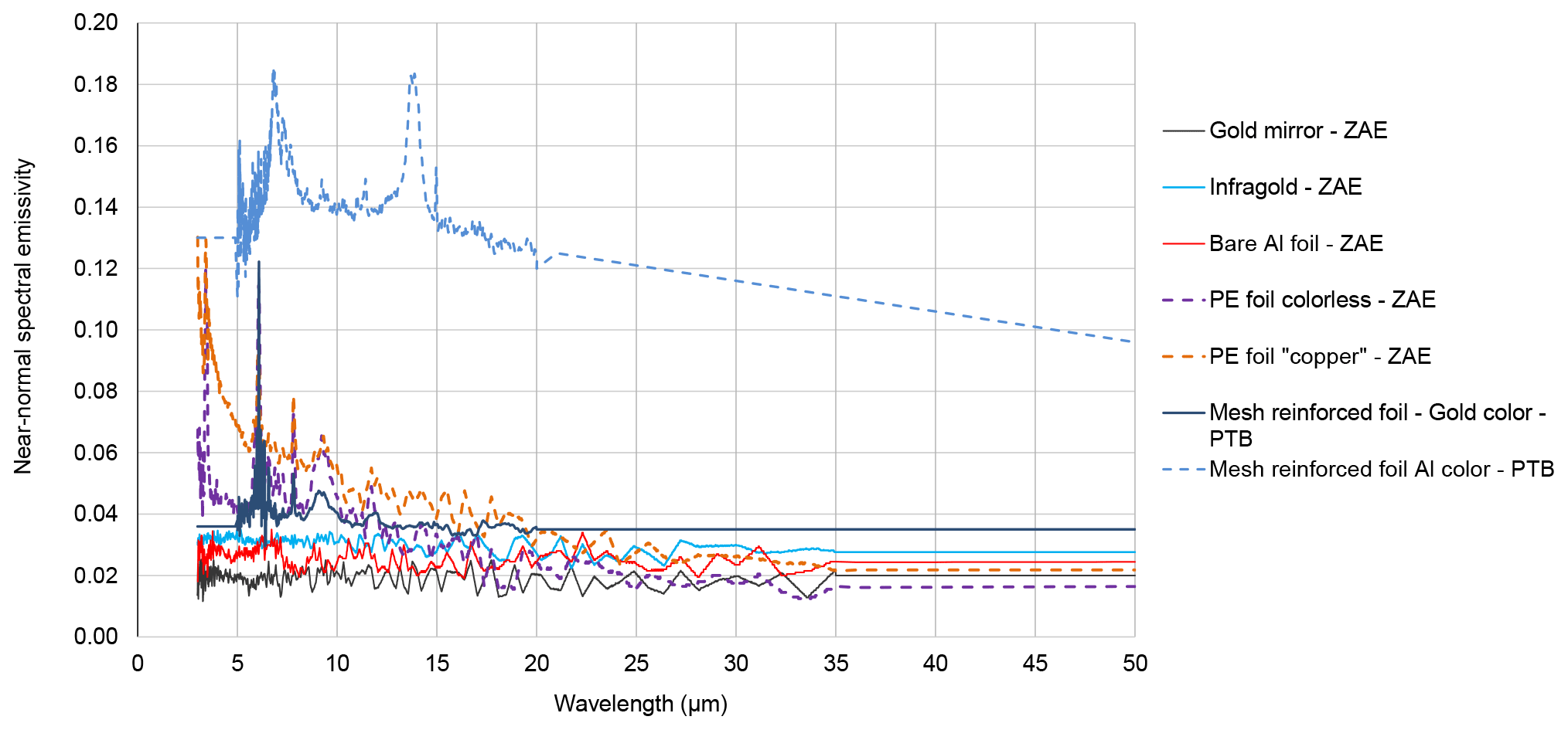
Figure 12Spectral near-normal emissivity curves of the tested reflective foils and solid materials.
The numerical calculation of the error requires knowledge of the sample spectral near-normal emissivity. In the EMIRIM project, three smooth reflective and two very non-smooth foils were tested. ZAE measured, with an integrating sphere (Manara et al., 2009), the spectral near-normal emissivities of three smooth foils in the spectral range 2 to 35 µm, and the PTB measured the spectral near-normal emissivities of the two very non-smooth foils in the spectral range 5 to 20 µm using the EMAF setup (Monte and Hollandt, 2010). The results are given graphically in Fig. 12. For application of Eqs. (12)–(15), spectral data are required from 3 to 50 µm for the sample spectral emissivity. Spectral domains of measurement being limited to 35 µm for ZAE and from 5 to 20 µm for the PTB, the spectral near-normal emissivities of the foils were extrapolated out of the spectral measurement domains assuming that the spectral emissivity is constant or varies linearly as a function of wavelength. The spectral emissivity curves are shown in Fig. 12; the extrapolated data can be identified by the non-noisy and straight portions of the curves. The extrapolations of spectral emissivities out of the measurement spectral domains are quite arbitrary, but it must be taken into account that these curves are only used to quantify a specific error of measurement and not to produce a result.
Table 1Error on the measured total near-normal emissivity due to the spectral radiometric response and due to the conditions of measurement with the TIR100-2 instrument (hemisphere temperature = 100 ∘C).

The errors on the measured total near-normal emissivities were calculated using the model above for the five tested foils and for the gold mirror coating used for calibration of TIR100-2 emissometers in the EMIRIM project. The calculation was done also for the very angular diffusing low-emissivity Infragold® coating from Labsphere Inc. (USA). The calculated errors are given in Table 1. From those results, the standard uncertainties retained for the specific spectral conditions of measurement are 0.003 and 0.005, respectively, for low-emissivity bare metal surfaces and for polyethylene metalized foils with a thin polyethylene over-coating on the metal reflective layer. We notice that, for the low-emissivity tested materials, the total near-normal emissivity measured with the TIR100-2 emissometer is systematically higher than the total near-normal emissivity defined by Eq. (12). This is due to the temperature of the hemisphere, which is higher than the temperature for which the total emissivity of the sample is calculated using Eq. (12). This gives more weight to short wavelengths for which the spectral emissivities of the samples are higher (Fig. 12).
4.2.5 Uncertainty due to the angular diffusion of the sample
A difference between the angular diffusion of the tested material and the angular diffusion of the low-emissivity standard (a mirror) is almost systematic when testing low-emissivity foils. It generates an error on the measured reflectance because the area of the heating hemisphere “viewed” by the radiometric system, through the reflection on the sample, is different. Moreover, the multi-reflections inside the cavity are different and dependent on the specularity of the sample. However, an uncertainty is already considered for the non-uniformity in temperature of the radiating hemisphere, and another uncertainty is considered for multi-reflections between the sample and the hemisphere. So, no uncertainty is considered specifically for the sensitivity to the angular diffusion of reflection of the sample.
Table 2Standard uncertainty on the measured total near-normal emissivity due to uncertainties on the temperatures of the sample being tested or of the standards used for calibration.
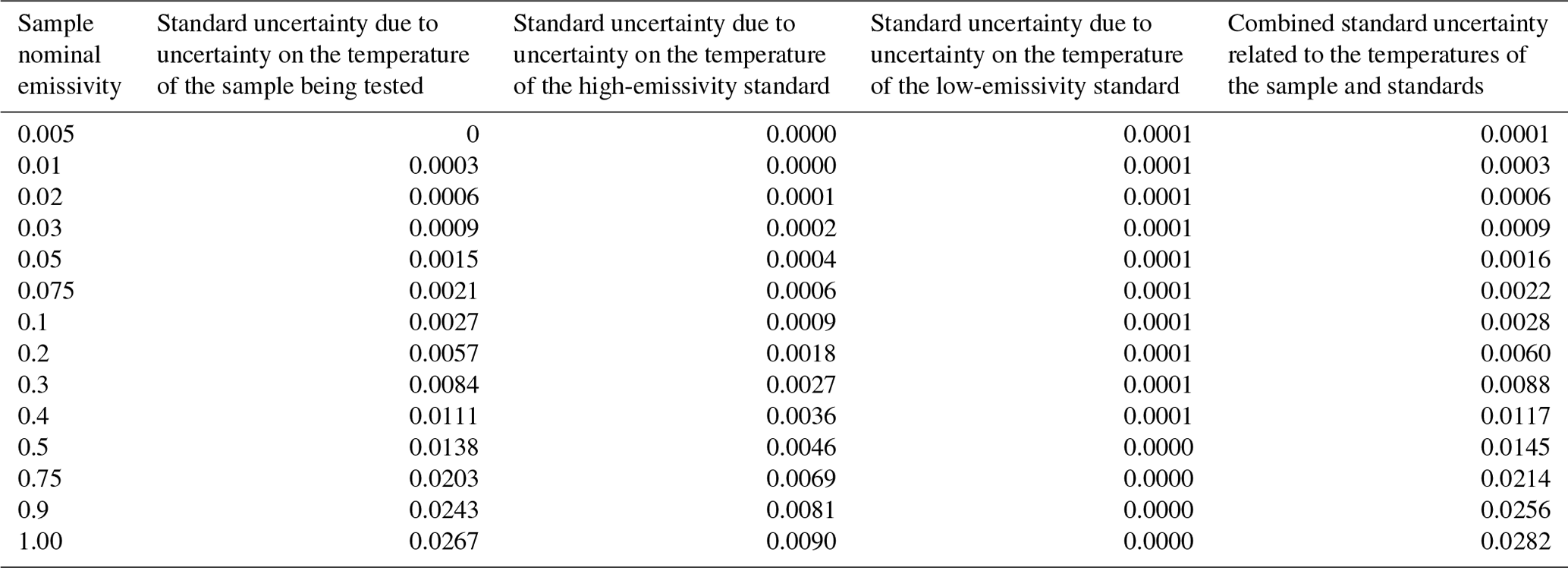
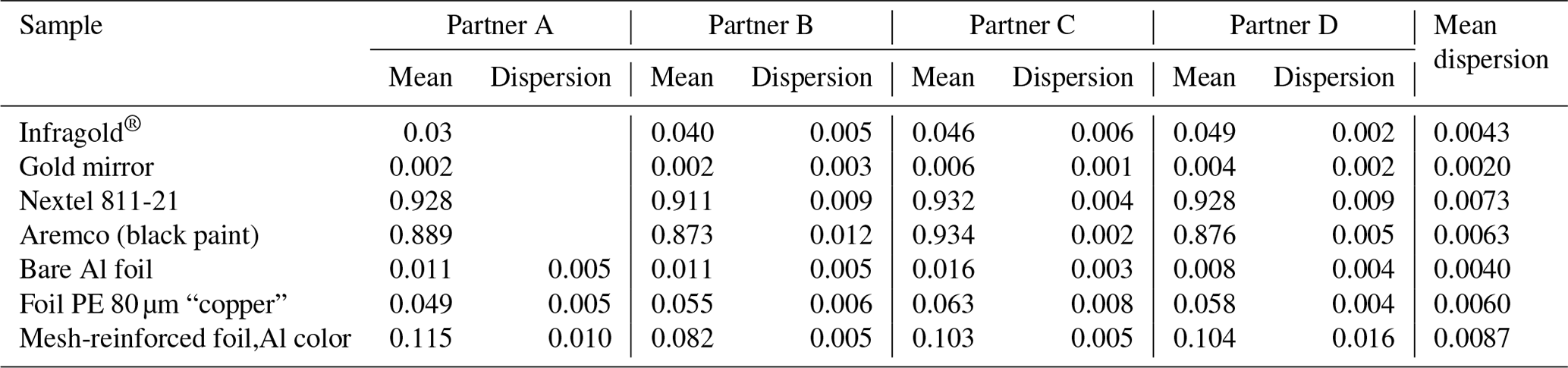
Table 3Results of repeatability measurements with TIR100-2 by partners in the EMIRIM project; the dispersion was calculated as the maximum value minus minimum value.
4.2.6 Uncertainty due to the uncertainties on the total near-normal emissivities of the calibrated standards
Equation (1) gives the total near-normal emissivity of the sample. The standard uncertainty on the measured emissivity due to the uncertainties on the values of the total near-normal emissivities of the standards is given by Eq. (17):
where u(εN) is the standard uncertainty on the emissivity of the low-emissivity standard and u(εH) is the standard uncertainty on the emissivity of the high-emissivity standard.
A low-emissivity standard of mirror type can be calibrated in total near-normal emissivity, by a national metrology institute, with a standard uncertainty of 0.011, and a high-emissivity standard, such as a metal plate coated with the high-emissivity Nextel 811-21, can be calibrated with a standard uncertainty below 0.01 (Hanssen, 2001; Monte and Hollandt, 2010; Scoarnec et al., 2014).
Table 4Total normal emissivity results obtained on 30 samples of each foil for uniformity tests.
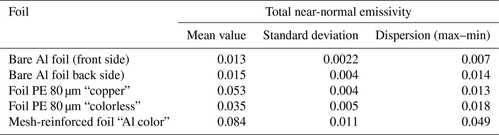
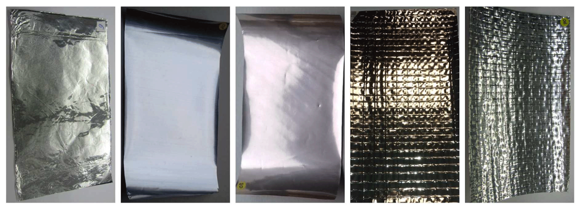
Figure 13Photos of the five tested reflective foils for validation of total near-normal emissivity measurements with the TIR100-2 emissometer. From left to right: bare aluminum foil, metalized polyethylene foil “Foil PE 80 µm – colorless”, metalized polyethylene foil “Foil PE 80 µm – copper”, metalized polyethylene foil reinforced by a mesh “Mesh-reinforced foil – Gold color” and metalized polyethylene foil reinforced by a mesh “Mesh-reinforced foil – Al color”.
4.2.7 Uncertainty due to non-constancy of the spectral near-normal emissivities of the standards
If the standards have a non-constant near-normal emissivity, then the sensitivity of the emissometer coming from the calibration is biased due to the fact that the standards give more relative importance to certain wavelengths for the signals measured during calibration. The effects of spectral variations of the spectral near-normal emissivities of the standards on the total near-normal emissivity measured on low-emissivity foils were quantified. Mean spectral linear variations were successively imposed on the spectral emissivities of the two standards; the signals measured were calculated using Eqs. (13)–(15), and the total near-normal emissivities of the tested foil and of the standards were calculated using Eq. (12). The error on the measured emissivity was calculated using Eq. (16). The low-emissivity standards considered for the quantification were a gold mirror and the Nextel black paint. For the two types of standards, the mean slopes of the spectral emissivity curves obtained by spectral measurement (Fig. 12) are below 10−4 µm−1 over the spectral range 2 to 35 µm. The results showed that, for a low-emissivity foil sample, the error on the measured total near-normal emissivity varies linearly with the mean slopes imposed on the spectral emissivity curves of the standards. When the mean slope is 0.00052 µm−1 for the low-emissivity standard, then the error on the measured total near-normal emissivity of the tested foil is 0.0021. The error on the measured total near-normal emissivity of the tested foil is below 2 × 10⁻⁵ when the mean slope is 0.00052 µm−1 for the spectral emissivity curve of the high-emissivity standard. Those results show that the selection of the standards regarding a mean trend for the spectral variations of spectral emissivity is not critical. A mean slope of 0.00052 µm−1 corresponds to a variation of 0.025 for the spectral emissivity from 2 to 50 µm. For the low-emissivity standard, protected metal mirrors are appropriate. For measurements of emissivity on low-emissivity foils, the spectral curve of the high-emissivity standard is less important. A high-emissivity standard with a spectral emissivity curve having a mean slope of 0.003 µm−1 generates an error on the measured emissivity below 10−4 for a low-emissivity foil.
The standard uncertainty considered for the non-constancy of the spectral emissivities of the standards is 0.001.
4.2.8 Uncertainty due to the temperatures of the working references and due to the temperature of the sample being tested
The variations of measured emissivity due to variations of temperatures of the sample being tested or due to variations of reference sample temperatures were calculated using the radiosity modeling. Table 2 gives the standard uncertainty on the measured emissivity due to a standard uncertainty of 3 K on the sample temperature and of 1 K on the temperatures of each standard.
For measurements on low-emissivity samples (ε≤0.1), the sample temperature is not critical. The standard uncertainty remains below 0.0015.
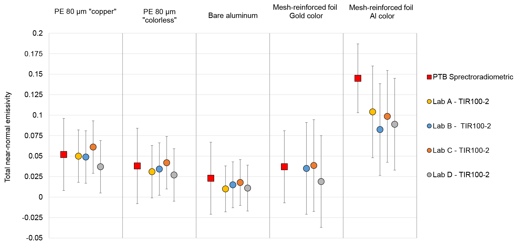
Figure 14Comparison of total near-normal emissivity results from four TIR100-2 emissometers to results from EMAF at the PTB, for five reflective foils.
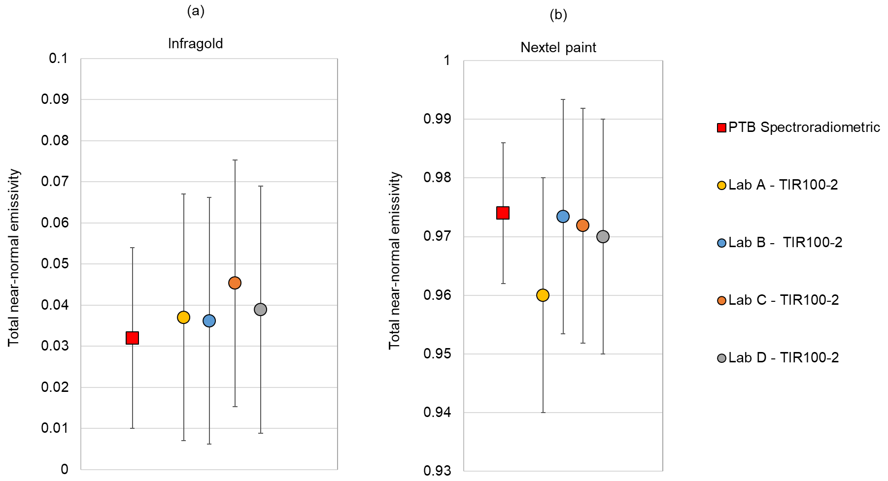
Figure 15Comparison of total near-normal emissivity results from four TIR100-2 emissometers to results from EMAF at the PTB, (a) Infragold® coating, and (b) Nextel 811-21 black paint.
4.2.9 Repeatability of measurements
In the EMIRIM project, four partners repeated measurements with a TIR100-2 instrument on different materials; the results are given in Table 3.
From the repeatability test results, the standard uncertainties retained for repeatability are 0.0015, 0.002, 0.003 and 0.005, respectively, for low-emissivity flat mirrors, bare metal foils, low-emissivity polyethylene foils and very non-flat “low-emissivity” polyethylene foils. Those uncertainties integrate some non-uniformity of the tested materials.
4.2.10 Uncertainty due to the non-homogeneity in emissivity of the material
This uncertainty is specific to the tested material. To obtain a representative value of the emissivity of a reflective foil, several measurements must be performed in different locations of the materials. A partner in the EMIRIM project performed total normal emissivity measurements, using a TIR100-2 instrument, on 30 different samples of four foils. The results are given in Table 4 and show that for smooth foils the dispersions of results are a bit higher than the ones obtained in repeatability tests. For a smooth reflective foil made of a metal-coated polymer foil, the increase in dispersion is about 0.007, which is quite low. For the bare aluminum foil, the increase in dispersion is about 0.003, which is also low. For the tested “mesh-reinforced foil”, the dispersion of results is very large; this is due to the high non-uniform structure of the foil (Fig. 13).
Table 5Uncertainty budget for measurement of total near-normal emissivity on reflective foils with the TIR100-2 emissometer.

4.3 Combined standard uncertainty for reflective foils
From the standard uncertainties quantified for each source of uncertainty, the combined standard uncertainty was quantified for the measurement of the total near-normal emissivity of the reflective foils with a TIR100-2 emissometer.
For smooth low-emissivity foils, the main uncertainty source is the calibration in total near-normal emissivity of the standards used for calibration. In fact, the uncertainty on the emissivity value of the low-emissivity standard is the main source of uncertainty.
For foils with very rough surfaces, the dispersion of individual results is a main source of uncertainty on individual results. However, it remains possible, and it is highly recommended to determine a mean emissivity value with a lower uncertainty by repeating several measurements.
5.1 Comparison of TIR100-2 to the EMAF reference technique at the PTB
In the EMIRIM project, four partners have performed measurements on five reflective foils, three smooth foils and two “mesh-reinforced” foils. Pictures of the tested foils are given in Fig. 13. Measurements were also performed on the very diffusing low-emissivity Infragold® coating and on the Nextel 811-21 high-emissivity black paint on a flat surface. The results for Infragold® and Nextel paint are given in Fig. 15.
For those measurements, the TIR100-2 emissometers were calibrated with gold mirrors and Nextel 811-21 paint calibrated in total near-normal emissivity at the PTB using the primary reference spectroradiometric technique EMAF. The results are compared in Fig. 14 to the results from the EMAF setup at the PTB. The expanded uncertainties represented in Fig. 14 for results from TIR100-2 devices are the uncertainties given in Table 5.
5.2 Analysis of results
The results obtained with the four tested TIR100-2 instruments are grouped with dispersions less than 0.01, 0.025, 0.01 and 0.015, for the bare aluminum foil, for the smooth and non-smooth reflective foils, for Infragold® and for Nextel 811-21 paint, respectively. The results from TIR100-2 devices are remarkably grouped for the heavily non-smooth foils.
The differences between the results from TIR100-2 and those from the primary measurement setup EMAF at the PTB are below 0.014 for Infragold® coating, showing that TIR100-2 emissometers are not very sensitive to the angular diffusion of the radiation reflected by the sample.
The correct grouping of the results for the smooth reflective foils and the good accordance between the results from TIR100-2 emissometers and those from EMAF confirm that a calibration with a specular surface is appropriate for measuring total near-normal emissivity of low-emissivity smooth foils. The comparison to the reference results from the PTB confirms also the validity of the expanded uncertainty of 0.03 for measurement of total near-normal emissivity of smooth reflective foils.
For one of the heavily non-smooth foils, the results from TIR100-2 devices are far from those obtained with the EMAF setup, with differences above 0.04. For the second heavily non-smooth foil, the results are in good agreement with EMAF results. The reasons for the non-accordance of results for one of the non-smooth foils are not known. More experiments should be done to analyze the performance of TIR100-2 emissometers for emissivity measurements on non-smooth low-emissivity surfaces.
For the first time, the TIR100-2 emissometer was characterized in detail in terms of metrological performance for the measurement of total near-normal emissivity of low-emissivity foils found as external surfaces of some thermal insulation products. Each parameter important for the application of the measurement model implemented in the device was analyzed, and an uncertainty budget was established. The comparison to a primary reference measurement setup, for several types of low-emissivity foils with different surface structures, confirmed the trueness of measurements and validated the assessed expanded uncertainty for measurements on smooth reflective foils. For those foils, the expanded uncertainty is around 0.03, and the main source of uncertainty is the uncertainty on the emissivity value of the low-emissivity standard used for calibration.
For the heavily non-smooth reflective foils tested, the result from the TIR100-2 emissometer was significantly different from the result from the reference setup. At this stage, giving a conclusion about the performance of TIR100-2 emissometers for measuring accurately the total near-normal emissivity of reflective foils with very structured surfaces is difficult. More measurements on diverse structured foils are required to draw conclusions about the performance for such foils.
To facilitate the comparisons of the emissivity measurement techniques for heavily structured surfaces, it would be useful to have samples of solid materials with structured surfaces. Such samples would allow performance of measurements on the same objects. This would facilitate the analysis of the results by eliminating potential dispersion between samples and avoid the modification of the morphology of surfaces, as may be the case for most reference techniques when the sample of foil must be maintained in contact with a flat surface such as a heating system.
All relevant measurement results are shown in the publication. However, the underlying measurement data are not publicly available and can be requested from the authors, if required.
JH and GF characterized a TIR100-2 emissometer. EK, AA, CM, and MA performed spectral measurements on foils. AK lent two emissometers for tests and supplied a sample of paint. EP performed reproducibility measurements. HS performed measurements. JH wrote the paper with contributions from MA and JM.
One of the co-authors has an interest in the company (INGLAS) producing and commercializing the instrument that is the object of the publication. The INGLAS company did not influence the performance characterization of the instrument.
This project, 16NRM06 EMIRIM, has received funding from the EMPIR programme co-financed by the Participating States and from the European Union's Horizon 2020 research and innovation programme.
This paper was edited by Bernhard Jakoby and reviewed by three anonymous referees.
Blake, T. A., Johnson, T. J., Tonkyn, R. G., Forland, B. M., Myers, T. L., Brauer, C. S., Su, Y-F., Bernacki, B. E., Hanssen, L., and Gonzalez, G.: Methods for quantitative infrared directional-hemispherical and diffuse reflectance measurements using an FTIR and a commercial integrating sphere, Appl. Optics, 57, 432–446, https://doi.org/10.1364/AO.57.000432, 2018.
CEN: Standard EN 16012+A1 – Thermal insulation for buildings – Reflective insulation products – Determination of the declared thermal Performance, European Committee for Standardization, Brussels, Belgium, 2015.
CEN/TC89/WG12: Note of internal communications between members of working group CEN/TC 89/WG 12, CEN/TC89/WG12, UK, 2013.
Dexter: 2M Thin Film Based Thermopile Detector – Technical Specifications, available at: https://dexterresearch.com/product-finder/2m-thin-film-based-thermopile-detector-highest-sensitivity/# (last access: 23 November 2020), Dexter Research Center, Inc., Dexter, MI, USA, 2020.
Clarke, F. J. J. and Compton, J. A.: Correction Methods for Integrating-Sphere Measurement of Hemispherical Reflectance, Color Res. Appl., 11, 253–262, https://doi.org/10.1002/col.5080110406, 1986.
Driscoll W. G. and Vaughan W.: Handbook of Optics, McGraw-Hill, USA, 1978.
European Commission: Directive 2010/31/EU of the European Parliament and of the Council of 19 May 2010 on the energy performance of buildings, available at: https://eur-lex.europa.eu/LexUriServ/LexUriServ.do?uri=OJ:L:2010:153:0013:0035:en:PDF (last access: 22 November 2020), European Commission, Brussels, Belgium, 2010.
Geotti-Bianchini, F. and Lohrengel, J.: Measured angular distribution of the emissivity and calculated radiation heat transfer of architectural coated flat glass. Part 1. Theory, Glastech. Ber.-Glass, 62, 312–319, 1989.
Hanssen, L.: Integrating-sphere system and method for absolute measurement of transmittance, reflectance, and absorptance of specular samples, Appl. Optics, 40, 3196–3204, https://doi.org/10.1364/AO.40.003196, 2001.
Inglas: TIR100-2, Operating Instructions, V3.4, Inglas GmbH & Co. KG, Bermatingen, Germany, 2014.
Inglas GmbH & Co. KG: Introducing TIR100, available at: https://inglas.org/tir100/ (last access: 22 November 2020), 2020.
ISO: ISO 6946:2017: Building components and building elements – Thermal resistance and thermal transmittance – Calculation methods, International Organization for Standardization, Geneva, Switzerland, 2017.
Isotech: Calibration certificate No 659/270/46/09, available at: https://isotech.co.uk/wp-content/uploads/2020/09/BlackBodyCertificate-gemini.pdf (last access: 5 February 2021), Isothermal Technology Limited, Southport, Merseyside, UK, 2021.
Janssen, D. and Lohrengel, J.: Investigation and development of a method for the measurement of the emissivity of glass, Report EUR 13487 EN, Commission of the European Communities, Luxembourg, 1991.
JRP EMIRIM: Improvement of emissivity measurements on reflective insulation materials, available at: http://projects.lne.eu/jrp-emirim/ (last access: 22 November 2020), Laboratoire National de Métrologie et d'Essais, Paris, France, 2017.
Kononogova, E., Adibekyan, A., Monte, C., and Hollandt, J.: Characterization, calibration and validation of an industrial emissometer, J. Sens. Sens. Syst., 8, 233–242, https://doi.org/10.5194/jsss-8-233-2019, 2019.
Manara, J., Arduini-Schuster, M., and Hanssen, L.: Infrared-optical intercomparison measurements for evaluating the accuracies of the achieved results, High Temp.-High Press., 38, 259–276, 2009.
Monte, C. and Hollandt, J.: The determination of the uncertainties of spectral emissivity measurements in air at the PTB, Int. J. Metrologia, 47, 172–181, https://doi.org/10.1088/0026-1394/47/2/S14, 2010.
Rubin, M., Arasteh, D., and Hartmann, J.: A correlation between normal and hemispherical emissivity of low-emissivity coating on glass, Int. Commun. Heat Mass, 14, 561–565, https://doi.org/10.1016/0735-1933(87)90020-0, 1987.
Scoarnec, V., Hameury, J., Verdure, A., Blanchin, A., Raulet, D., and Hay, B.: Développement d'un réflectomètre absolu pour l'étalonnage de miroirs dans l'infrarouge, Revue Française de Métrologie, 33, 29–38, https://doi.org/10.1051/rfm/2014004, 2014.
Siegel, R. and Howell, J. R.: Thermal Radiation Heat Transfer, McGraw-Hill Book Company, USA, 1972.
low-emissivity effectto increase the thermal resistance, but the uncertainties of measurements on low-emissivity foils were not known. The study allowed the determination of the uncertainty through the detailed analysis of the measurement principle and the determination of the influences of the parameters. The measurement results were validated by comparison to a reference measurement setup.