the Creative Commons Attribution 4.0 License.
the Creative Commons Attribution 4.0 License.
 | 08 Apr 2022
Acoustophoresis in suspensions with local and time-discrete sound fields based on the time reversal technique
Philipp Hörnlein
Sebastian Wöckel
Hendrik Arndt
Jörg Auge
In this paper, a new approach of three-dimensional acoustic particle manipulation (acoustophoresis) in closed and liquid-filled vessels based on the time reversal technique is discussed. Based on simulation studies, this work investigates the technical prerequisites to achieve appropriate acoustic radiation forces (ARFs) for the manipulation of small particles with the time reversal method by utilizing multiple reflections in a closed vessel. The time-discrete and localized acoustic pressure field required for this purpose is generated by a time reversal mirror composed of 24 piezoceramic transducers. The paper also gives an outlook on practical evaluation of the simulation results based on a demonstrator setup.
- Article
(11785 KB) - Full-text XML
- BibTeX
- EndNote


The manipulation of cells and particles in fluids has a variety of applications in medical and biotechnological contexts. In particular, acoustophoresis, in which particles and cells are manipulated based on acoustic forces, is becoming increasingly important because it is contactless and biocompatible and does not require markers (Lenshoff and Laurell, 2012; Laurell et al., 2007). In the medical field, for example, acoustophoresis is used to remove lipid droplets from human blood (Petersson et al., 2004), to produce blood plasma – plasmapheresis (Lenshoff et al., 2009) – or to extract tumor cells from blood (Antfolk et al., 2017) for closer examination. In the context of biotechnology, the focus is on separating (Simon et al., 2017; Ma et al., 2016), sorting (Chitale et al., 2017) and accurately positioning (Ding et al., 2012) cells, particles and liquid droplets in surrounding fluids. Specifically, in lab-on-a-chip applications in microchannels, separation and sorting occur during the flowing process of the suspension. In all of the applications and demonstrations mentioned above, the necessary acoustic forces are generated in a stationary manner using bulk acoustic waves (BAWs) (Leibacher et al., 2015; Dauson et al., 2015), surface acoustic waves (SAWs) (Johansson et al., 2012) or focused acoustic fields (acoustic vortices) (Marzo et al., 2018; Riaud et al., 2015). The so-called acoustic radiation force (ARF) is often used for the manipulation and can be found analytically under restrictions. For spherical and small particles (), the force can be approximated with the help of the Gor'kov potential (Gor'kov, 1961). In addition to the size of the object, the force effect depends on the acoustic contrast of the object to the surrounding medium (Augustsson et al., 2010). If a positive acoustic contrast factor is present, the objects are transported towards the pressure nodes of the acoustic wave, while a negative acoustic contrast factor results in a force effect towards the anti-nodes. However, there are also applications in which the ARF is combined with the force effect due to acoustic flows. Especially with focused acoustic fields, specific force effects on single or multiple objects can be achieved, which is the reason these acoustic fields are also called acoustic tweezers. The generation of the focused fields is currently based on either ultrasonic phased array technology (Marzo et al., 2015), passive systems (resonators, Jiang et al., 2016; phase plates, Terzi et al., 2017; diffraction gratings, Jiménez et al., 2016) or special transducer geometries (Baudoin et al., 2019). However, all these technical systems have limitations when focusing in 3D in closed vessels (cavities), such as small beakers or Petri dishes, because the reflection effects that occur interfere with or even completely prevent the focusing effect. In addition, the presented systems, except the phased array systems, usually do not offer the possibility to move the objects in space by electronically controllable variation of the acoustic field, which is why often additional electromechanical traversing systems are needed.
To circumvent the previous limitations, this work will investigate whether or not the ultrasonic time reversal technique (Fink, 1992; Wu et al., 1992; Cassereau and Fink, 1992) can be used to generate a suitable sound field in a fluid-filled vessel, specifically to take advantage of the previously limiting multiple reflections in favor of focusing. The objective is to realize a three-dimensional, composited, transient and localized sound field geometry, with the help of which one or more particles can be safely captured and displaced in space. In this application the starting point for time reversal focusing is a fluid-filled vessel to which the time reversal mirror is non-invasively coupled. The time reversal mirror is composed of 24 piezoceramic transducers that are attached to the bottom of the vessel as an annular structure. The basic methodology of time reversal focusing is based on a calibration of focal points (Fig. 1). The calibrated focal points can be variably excited in different combinations after the calibration procedure is completed and allows adjustable sound field geometries to be constructed. In the first step of the calibration process, the piezoceramic transducers w are excited one after the other with a calibration signal uw(t). At the desired focal point k, the resulting sound pressure pk(t) is measured by means of a needle hydrophone and is converted afterwards into an voltage signal. Based on the calibration signals Uw(ω) and the corresponding sound pressure curves Pk(ω) in the frequency domain, the transfer function Hkw(ω) from each transducer to the desired focal point can be calculated with Eq. (1).
The inverse Fourier transform of the transfer function Hkw(ω) yields the corresponding impulse response hkw(t) in the time domain (Eq. 2).
Due to reversing the impulse response signals in the temporal regime, the so-called time reversal signals are calculated with Eq. (3).
By re-emitting the time-reversed signals at the associated transducers, the transfer functions from the transducers to the desired focal point are compensated, which results in a strong focusing effect at the former position of the needle hydrophone. If this calibration is carried out systematically for several positions along a 3D-grid within the vessel, it becomes possible to focus on different points. By superposition of the time reversal signals for several focal points, simultaneous focusing on various points can also be realized. In this way, almost arbitrarily composed sound field geometries can be constructed. However, the complexity of the sound field is limited by the resolution of the calibration grid, the bandwidth of the calibration signals and the aperture of the time reversal mirror. The aperture of the time reversal mirror can be specifically increased by ensuring the best possible reflection conditions when designing the vessel. Strong reflections at the edges of the vessel cause multipath propagation of the sound waves. Here, each reflection acts like an additional sound source, which leads to an artificial enlargement of the aperture of the time reversal mirror. In order to use this effect, it is important to record the whole signal in the calibration step. However, depending on the vessel under consideration, this sometimes results in high signal lengths of the time reversal signals. Thus, in practical applications, a compromise must be found between signal length and memory requirements in the signal generator.
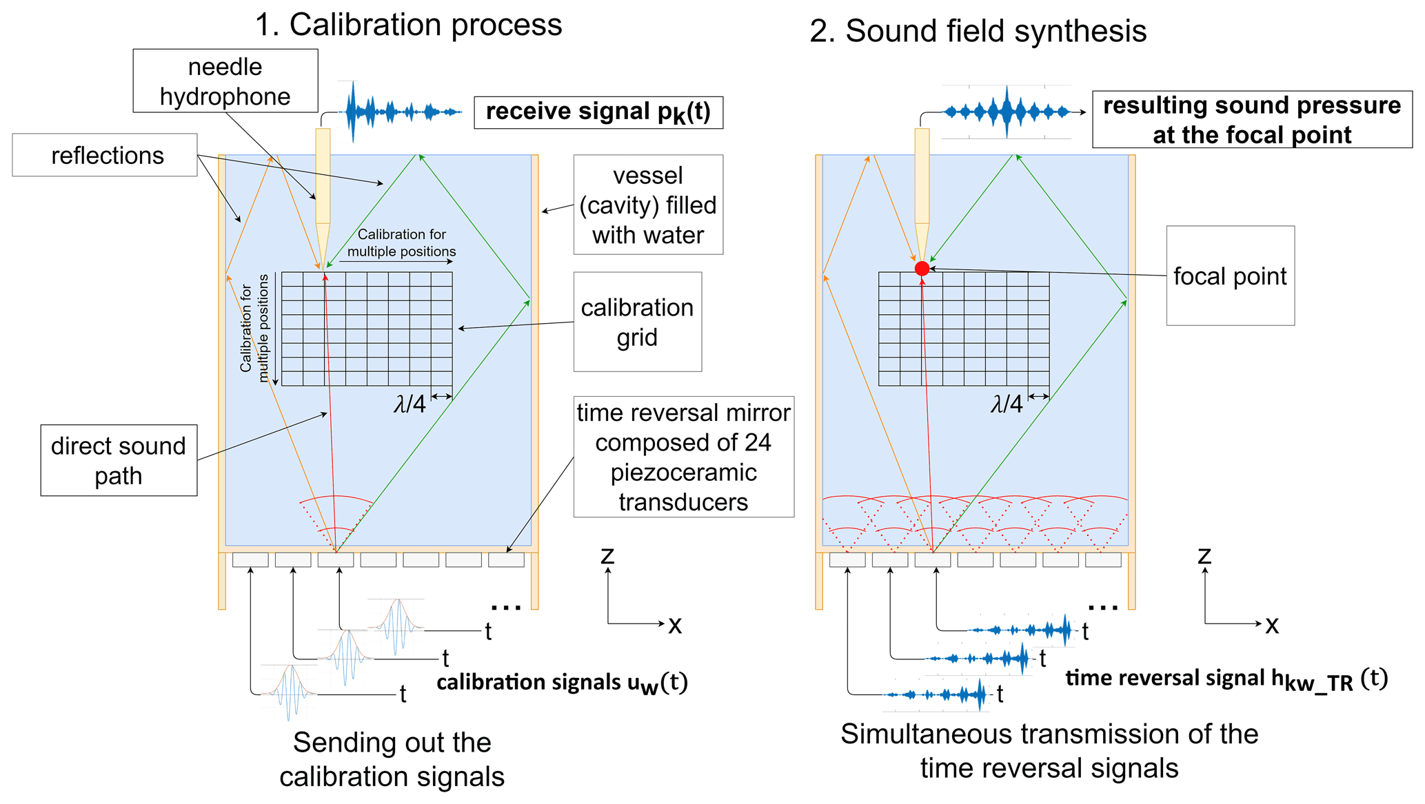
Figure 1Principle of 3D sound field focusing in closed vessels using time reversal technique.
Using the methodology described in Sect. 2, extensive simulation studies were carried out using COMSOL® Multiphysics on the feasibility of transient time reversal focusing and the generation of specific composed sound field geometries. The model that was developed in the scope of the studies is comprised of a hollow cylinder filled with water (inner diameter 35.64 mm, height 52 mm, wall thickness , wall material PMMA) and a time reversal mirror with 24 cylindrical piezoceramic transducers (diameter 4.9 mm, height 3 mm, material PIC255, resonance frequency 0.25 MHz) that is attached to the bottom of the vessel (Fig. 2). The bottom of the cylinder serves as a matching layer for low-loss coupling of the time reversal mirror. In order to be able to represent the overall behavior of the system as true as possible, the model takes into account both the transducers as piezoceramic material (with electric field excitation) and the properties of the cavity by means of a mechanical simulation. During the calibration process, for example, the piezoceramic transducers are excited with the calibration signal as a voltage signal uw(t). The resulting, mechanical deformation of the transducers is transmitted through the contact-coupling into the bottom plate of the cavity. The resulting vibration converts into a propagating acoustic wave in the water, where fluid acoustics applies. This is then calculated in the form of an acoustic simulation and subsequently visualized.

Figure 2Simulation model of the cylindrical vessel (inner diameter 35.64 mm, height 52 mm, wall thickness , bottom thickness , wall material PMMA) with a time reversal mirror composed of 24 piezoceramic transducers at the bottom. The integrated focal points are arranged around an example particle in the shape of the bottle trap.
The selected sound frequency of 0.25 MHz is an essential parameter for the size of the manipulable particles. Since the particles should be easily observable in the final setup, a particle diameter in the range of 0.5–2.0 mm was defined. As the calculations of Gor'kov (1961) and the investigations in Glynne-Jones et al. (2013) and COMSOL (2015) show, the ARF is proportional to the third power of the particle radius. However, this only applies to particle radii . Based on the comparison of both calculation methods, it becomes clear that the ARF begins to decrease when the particle radius exceeds 0.15λ. Particles, which are supposed to be effectively manipulated, must therefore be as large as possible but not larger than 0.15λ. For the investigations in this work and the chosen sound frequency of 0.25 MHz, this means a maximum particle diameter of 1.8 mm. Further, it should be noted that sound absorption increases with frequency. Additionally, it is more difficult to achieve high sound pressures at high frequencies which makes the kilohertz (kHz) range more practical than the megahertz (MHz) range. And ultimately, the computation time of the simulation itself is proportional to the fourth power of the frequency (∼f4) due to a finer mesh in 3D and a finer time resolution. All together, these limitations make it impractical to use higher working frequencies in the scope of the presented research.
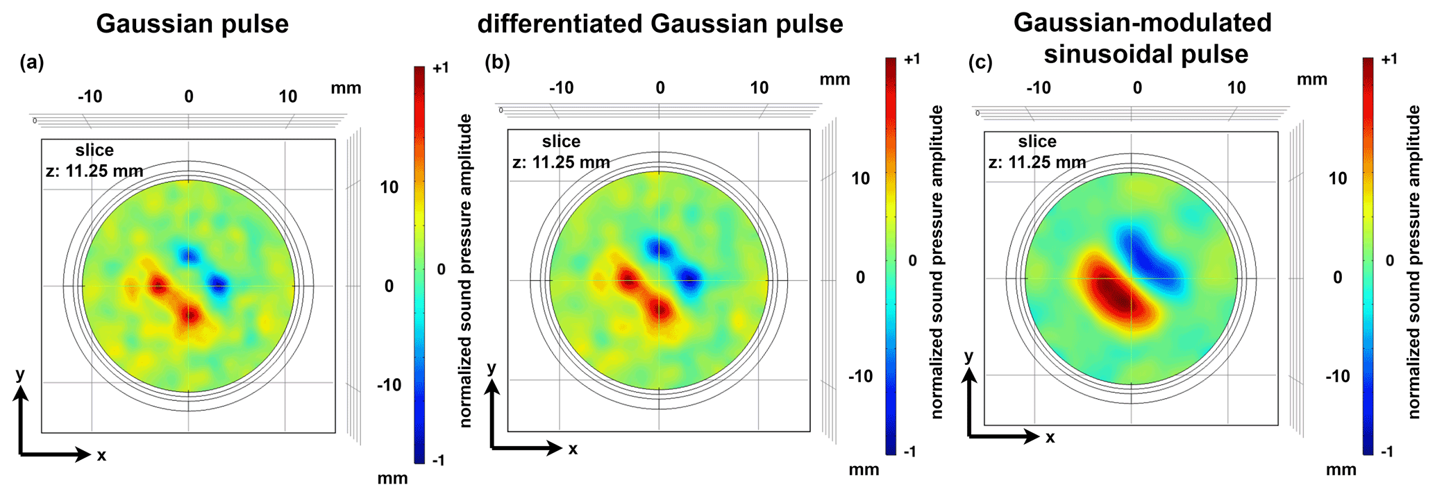
Figure 3Representation of the sound pressure field in the x–y plane of the cavity depending on the calibration signal used. (a) Gaussian pulse, (b) differentiated Gaussian pulse and (c) Gaussian-modulated sinusoidal burst.
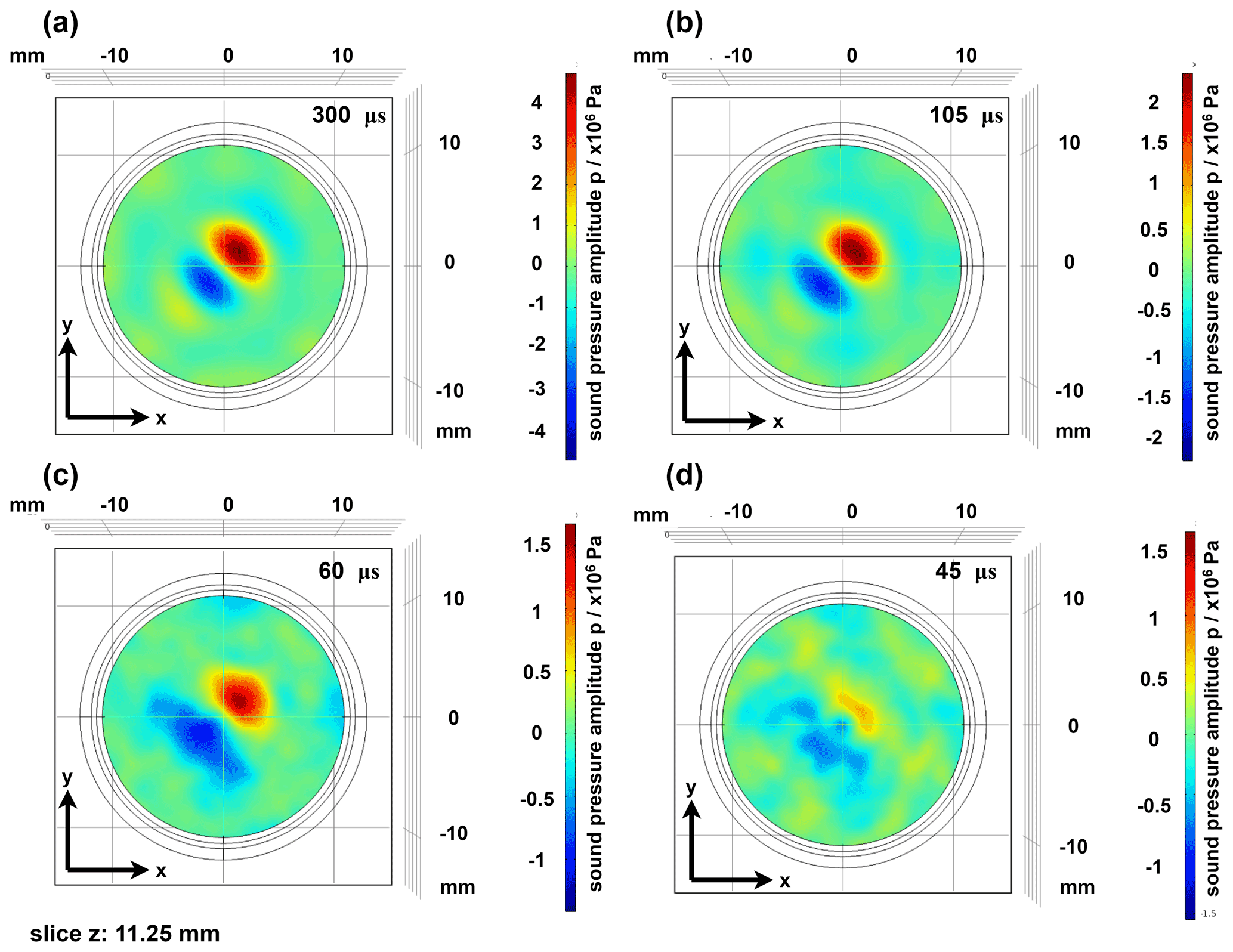
Figure 4Representation of the sound pressure field in the x–y plane as a function of the signal length of the time reversal signals. Signal lengths: (a) 300 µs, (b) 105 µs, (c) 60 µs and (d) 45 µs.
For the systematic investigation of sound field focusing in closed vessels, simulation studies were first carried out that specifically considered the parameters of sound field geometry, calibration signal and length of the time reversal signals. The studies were carried out on the basis of the simulation model shown in Fig. 2 but with the difference that the height of the cavity was reduced to 22.5 mm in order to reduce the calculation time of the simulation.

Figure 5Simulation example at 250 kHz: intensity plot of the acoustic pressure field of the bottle trap (a) in the x–y and (b) in the x–z plane in a cylindrical vessel with a time reversal mirror composed of 24 piezoceramic transducers attached to the bottom.
For stable particle trapping, a sound field geometry must be realized that generates a three-dimensional force effect on a trapped particle. Current research on the realization of particle traps using the phased array technique proposes various sound field geometries (twin trap, vortex trap, bottle trap) (Marzo et al., 2015). However, some of these geometries can only be realized to a limited extent on the basis of the time reversal technique, and their force effect is sometimes based on acoustic flow forces. This is mainly due to the fact that especially the twin trap and the vortex trap use elongated sound lobes, which are relatively difficult to realize on the basis of the time reversal technique, where individual focal points are excited. In addition, these sound field geometries are not locally limited, which means that they unintentionally influence particles in the surrounding. It was found that a modified version of the bottle trap is the ideal sound field geometry for the application at hand. In the version of the bottle trap used here, two focal points exist in each axis of a Cartesian coordinate system, facing each other at a defined distance – depending on the physical parameters of the particle and the surrounding medium (Fig. 2). The object to be manipulated is located between the focal points. In this way, a three-dimensional force effect based on ARF can be achieved.
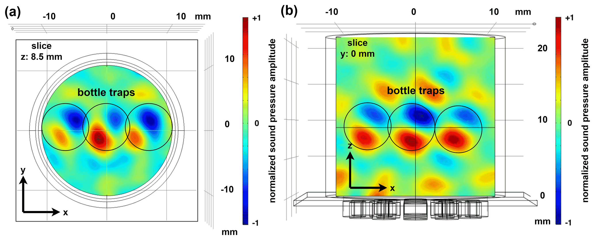
Figure 6Representation of the sound pressure field (a) in the x–y plane and (b) in the x–z plane in the cavity with simultaneous generation of three bottle traps.
In a further parameter study, the influence of different calibration signals on the focusing quality was investigated. As expected, the size of the focal point depends on the bandwidth of the calibration signal. The wider the bandwidth of the calibration signal, the smaller the resulting focus point becomes. For the studies the Gaussian pulse (bandwidth 0.5 MHz), the differentiated Gaussian pulse (bandwidth 0.35 MHz) and a Gaussian-modulated sinusoidal burst (bandwidth 0.0625 MHz) were used as calibration signals. The center frequencies of the differentiated Gaussian pulse and of the sinusoidal burst signal were 0.25 MHz. Figure 3 shows an example of a comparison of the focusing quality with simultaneous generation of several focal points and use of the excitation signals mentioned above at a focal point distance of λ (5.94 mm). The results of the simulation reveal that the highest spatial resolution can be achieved when using a Gaussian pulse because it has the largest bandwidth. One can see the distinct focal points that occur (Fig. 3a). When the calibration is performed with a differentiated Gaussian pulse, the focal points are still apparent, but they are also slightly enlarged and begin to merge together (Fig. 3b). Once the Gaussian-modulated sinusoidal pulse is applied, the focal points in their respective phase are not distinct anymore and blur into one larger accumulation (Fig. 3c). However, it can also be observed that the achievable spatial resolution with the Gaussian-modulated sinusoidal burst is sufficient enough to construct a composite sound field with a pressure node area in the center that allows particles to be captured safely.
Yet, in real applications, however, the bandwidth of the calibration signals is limited by the bandwidth of the piezoceramic transducers. By using the Gaussian-modulated sinusoidal burst, a practical compromise between focusing quality and applicability to real transducers can be achieved.
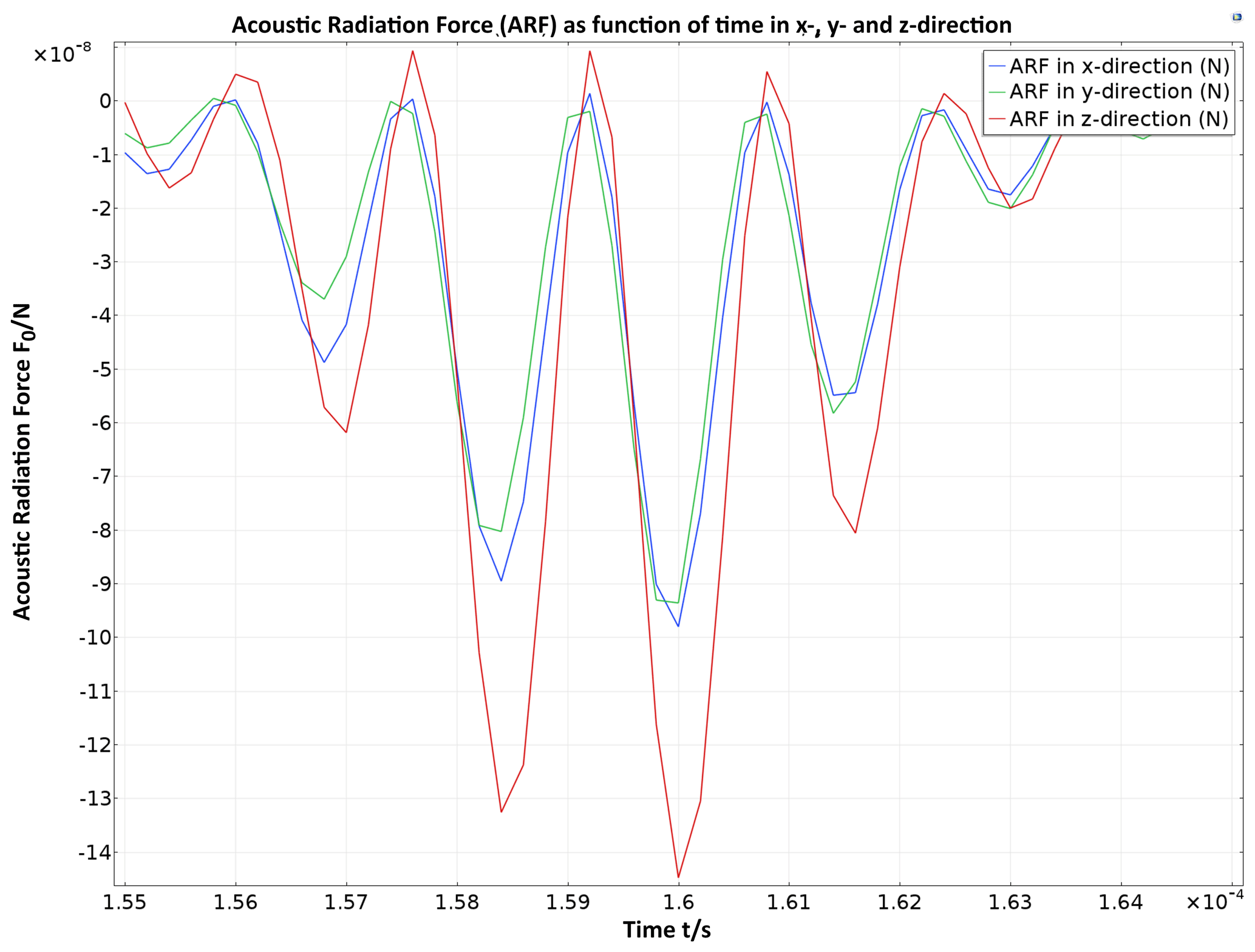
Figure 7Time course of the resulting acoustic radiation force in x, y and z direction on an test particle of polystyrene with a diameter of 0.6 mm. The particle is displaced 0.25 mm outside the center of the particle trap, resulting in a continuous negative force effect. It ensures that the particle is shifted back to the center of the particle trap.
In addition to the calibration signals used, the temporal length of the time reversal signals has a significant influence on the focusing quality. In one of the simulation studies, the signal length was successively reduced in order to investigate, which minimum signal length is required for suitable focusing. The signal lengths considered were integer multiples of the transit time of the acoustic waves through the largest dimension of the cavity (here cavity height). With the cavity height of 22.5 mm considered here and an average propagation speed of the waves of 1500 m s−1, this results in signal lengths that are an integer multiple of 15 µs. Figure 4 shows examples of the focusing quality for the signal lengths 300 (20-fold propagation time), 105 (7-fold propagation time), 60 (4-fold propagation time) and 45 µs (3-fold propagation time). From the results it can be seen that suitable focusing qualities are achieved for both the 105 and 300 µs signal lengths. However, if the signal length is shorter than 5 times the running time of the height of the cavity, there is a significant reduction in the focusing quality. From a signal length of 45 µs, clear focusing is no longer recognizable. Furthermore, it is noticeable that the achievable sound pressure is reduced by reducing the signal length. This can be explained by the fact that the energy contained in the signal is also reduced by the reduction of the signal length.
The investigations show that with a 24-transducer array a bottle trap sound field can be realized with the time reversal technique if the time reversal signals are at least as long as a sound wave needs to pass through the largest dimension of the vessel five times. However, if the signal length is increased, the number of transducers can be reduced, due to the presence of a higher number of multiple reflections acting like additional virtual sound sources. A quantitative investigation of the focusing quality as a function of the number of transducers in combination with the signal lengths used was not part of the studies. In practice, a compromise must be found between the number of channels and the signal length, i.e., the memory requirement per signal.
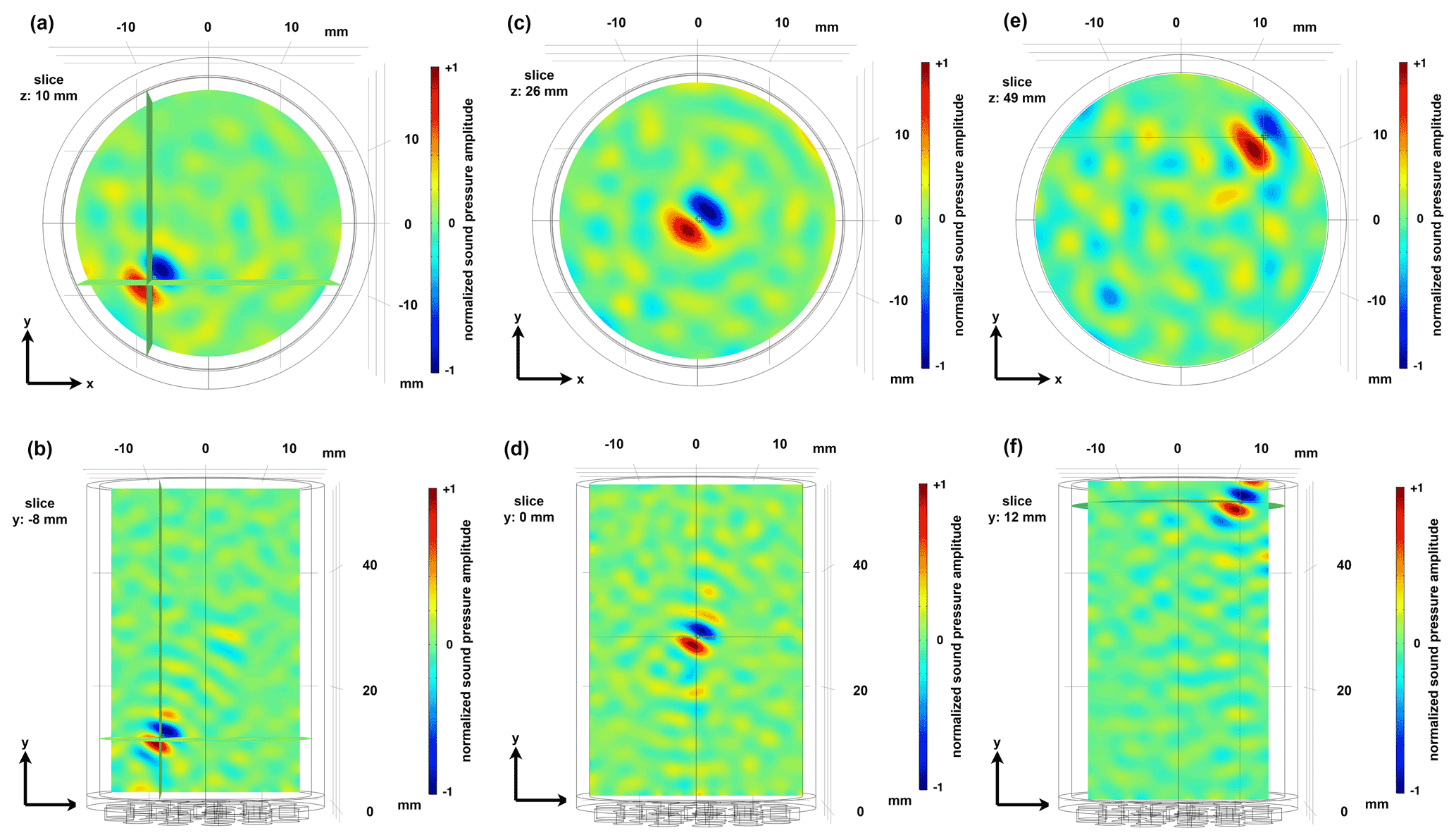
Figure 8Representation of the sound pressure field in the cavity when generating the bottle trap at three different positions. (a, b) Bottom left near the wall of the cavity and just above the time reversal mirror, (c, d) in the middle of the cavity and (e, f) top right near the water–air transition and near the wall of the cavity.
Furthermore, the parameter studies show that focal points close to each other with the same phase position merge into one focal point, which is due to the limited aperture of the time reversal mirror and the limited bandwidth of the calibration signals. To avoid merging, it is therefore useful to choose an inverse amplitude for opposite focal points, which enables the formation of a pressure node in between the opposing focal points of an axis. If opposite focal points have a spacing of with inverse amplitude, an acoustic field is created that corresponds in principle to a locally confined standing wave in three dimensions and is called bottle trap in this work (Fig. 5). Figure 5 shows the acoustic field in the cavity that was introduced in Fig. 2. The bottle trap was deliberately created off-center (+5.57 mm in positive x and y direction) and at a height of 37.5 mm to show that the size of the cavity and the position of the bottle trap in the cavity only have a minor influence on the focusing quality. The excitation signal is the Gaussian-modulated sinusoidal burst at a signal length corresponding to 20 times the cycle time of the height of the cavity. Corresponding multidimensional standing waves have already been successfully used for particle manipulation in other research (Ozcelik et al., 2018) but with the main difference that they are not localized and thus affect the entire volume. The locally resolved behavior and the spatial discretization are important advantages of the time reversal technique.
In this context, it was also investigated whether several bottle traps can be generated simultaneously in the vessel, so that several particles can be captured simultaneously and moved independently from each other. It is shown that the parallel generation of three bottle traps can be realized by simple superposition without any noticeable degradation of the focusing quality. The maximum number of three traps results from the dimensions of the vessel selected here and the frequency-dependent size of the sound field geometry. Figure 6 shows an example of the coexistence of three bottle traps at mid-cavity height.
However, by simply emitting the time reversal signals, only a transient focusing process is generated, the length of which depends on the type and bandwidth of the calibration signal. A corresponding transient focusing process can be taken from Figs. A1 and A2 in Appendix A, where the focusing process is presented in four successive time steps. The focusing process presented in Figs. A1 and A2 covers an entire period of the calibration signal and shows both a positive half-wave and a negative half-wave signal.
For stable particle trapping, it is necessary that the transient sound field is transformed into a quasi-stationary state. This can be realized by repeating the time reversal signals at high frequency with a deliberate signal overlap, as was already shown by Sutin et al. (2003). However, the signal overlap and signal repetition cause a degradation of the focusing quality, which can be effectively counteracted by increasing the signal length of the time reversal signals.
To quantify the force effect on particles, the ARF was determined using the simulated, calculated pressure field and the mathematical approach according to Glynne-Jones et al. (2013) and COMSOL (2015) on an exemplary introduced particle of polystyrene with a diameter of 0.6 mm (). Levitation of such a particle in water requires a force of at least 75 nN acting against the weight force. The particle was pushed out 0.25 mm from the center of the particle trap in all directions for the study to simulate a trapping process. The required force effects in all three dimensions (F0) can already be achieved with transducer voltages of approximately 20 VPP (Fig. 7). Furthermore, it is noticeable that the ARF in the z direction is significantly larger than in the x and y direction, which is a consequence of asymmetries in the acoustic pressure field. During the focusing process, temporarily higher sound pressures occur in the z axis of the cavity than in the x and y axis, which results in a higher force effect. This is due to the fact that the direct field (direct radiation direction of the transducers) with the maximum possible pressure amplitude acts primarily in the z direction. In all other directions, on the other hand, signal components resulting from reflections on the cavity walls are effective for the most part. The asymmetry of the field thus also varies with the length of the time reversal signals. The shorter the time reversal signals, the stronger this effect becomes, since fewer reflection processes in the cavity are taken into account. With a lengthening of the time reversal signals, the influence decreases and finally converges.
The displacement of the particle out of the particle trap does not result in a force curve symmetrical to 0 N. Instead, the force curve is shifted into the negative quadrant. It can be deduced that the particle is “pushed” back into the center of the particle trap.
The displaceability of the test particle caused by the control electronics was checked by successively generating the sound field geometry at different positions in the vessel. In this study, a deterioration of the focusing quality near the vessel wall or at the water–air boundary layer was not observed (Fig. 8). It can therefore be assumed that a trapped particle can also be transported variably in the vessel.
In the context of this work and on the basis of extensive simulation studies, it was investigated whether, with the use of the time reversal technique, an acoustic field can be generated in a closed and liquid-filled cavity, which enables transient acoustophoresis. It was explained that ideal sound field is a special type of a bottle trap, which consists of six individual focal points and creates a three-dimensional force effect on an inserted particle. Additionally, it was shown that such a composite sound field can be realized if the pre-calibrated time reversal signals have at least a time length that corresponds to 5 times the transit time of the acoustic wave through the largest dimension of the cavity. The simulation and evaluation revealed that the sound field can be translated in space and therefore exert a force on an inserted polystyrene test particle that is sufficient for acoustophoresis. In a final simulation, it was shown that several particle traps can be generated simultaneously within the cavity, so that, in theory, several particles can be manipulated independently of each other.
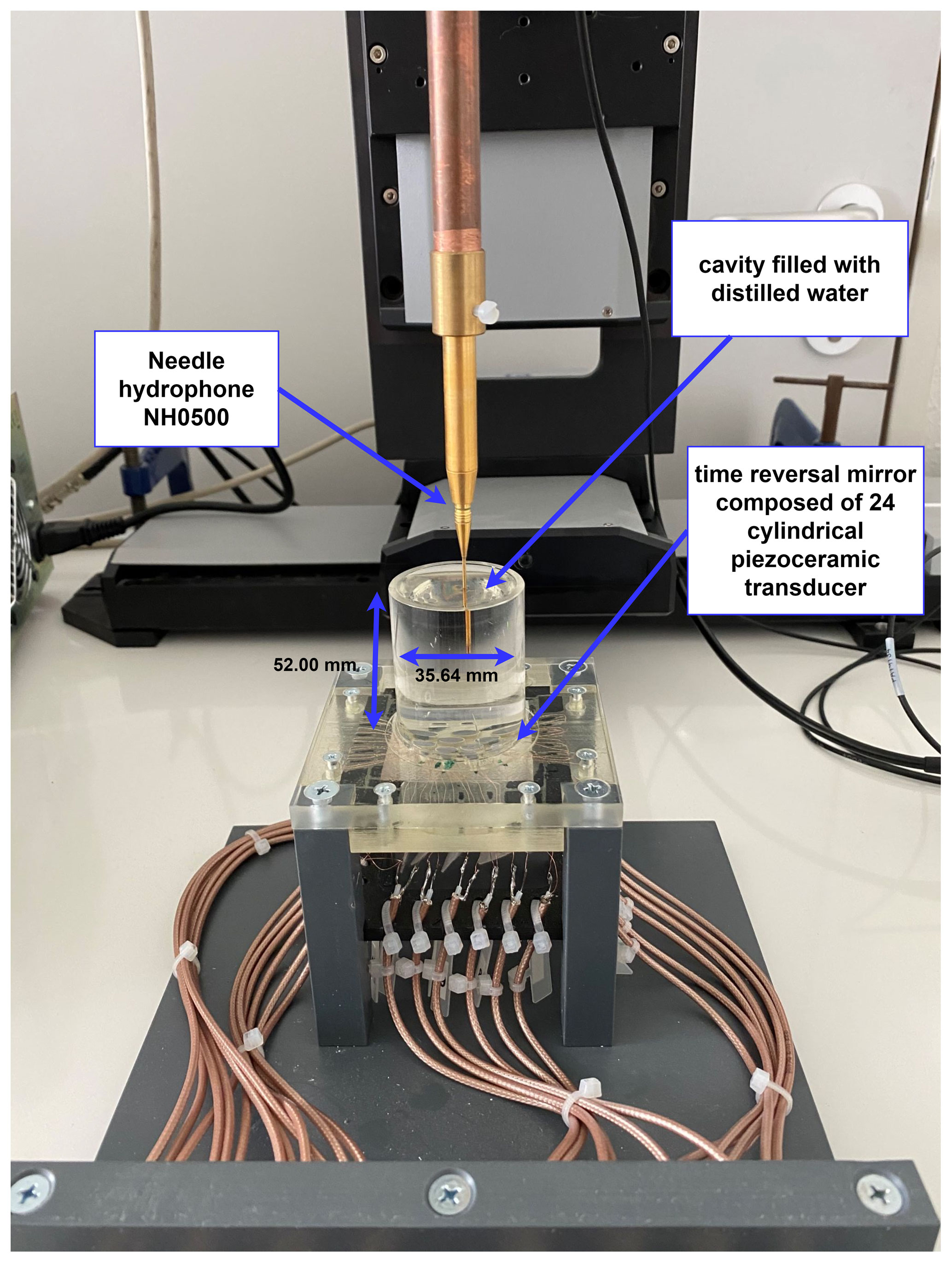
Figure 9Demonstrator realized on the basis of the simulation results, composed of the water-filled cavity and the time reversal mirror. The cavity contains a needle hydrophone for the time reversal calibration.
For the experimental validation of the simulation results, the demonstrator shown in Fig. 9 was realized. Analogous to the simulation model, the demonstrator consists of a cylindrical vessel filled with water (inner diameter 35.64 mm, height 52 mm, material PMMA). The time reversal mirror composed of 24 cylindrical piezoceramic transducers (diameter 4.9 mm, height 3 mm, material PIC255) is coupled to the bottom of the vessel. The bottom of the cylindrical vessel serves as a matching layer to enable the lowest possible loss of acoustic coupling. A needle hydrophone (Precision Acoustics NH0500, frequency range from 0.1 to 20 MHz) is placed inside the cavity. The hydrophone is used for the calibration of the focal points and the subsequent validation of the focused sound field.
The practical realization of the bottle trap particle trap as well as the demonstration of acoustophoresis will be part of a further publication.
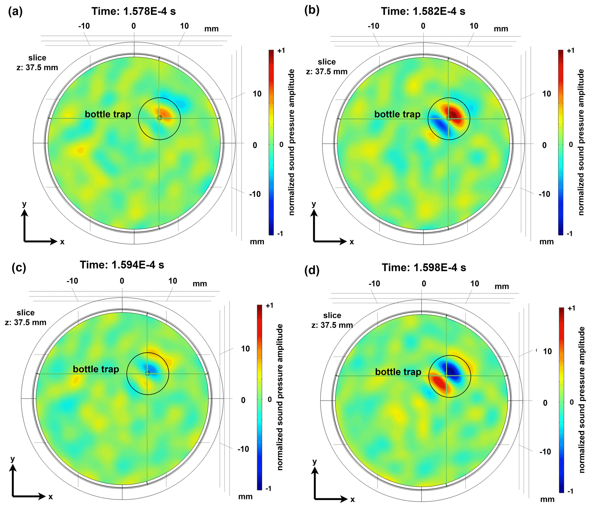
Figure A1Intensity plot of the acoustic pressure field of the bottle trap during the focusing process in the x–y plane in the cylindrical vessel during four different times.
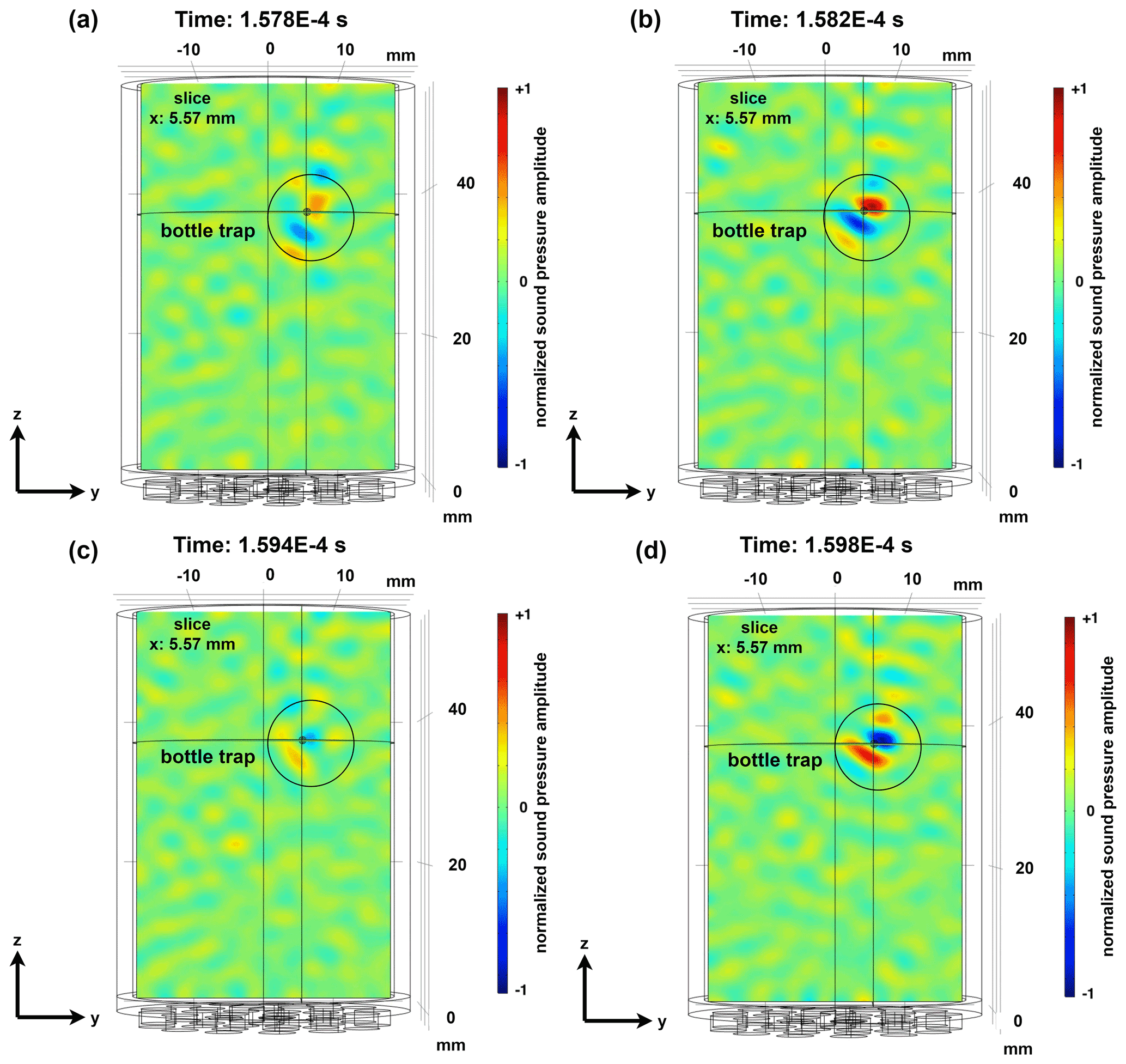
Figure A2Intensity plot of the acoustic pressure field of the bottle trap during the focusing process in the y–z plane in the cylindrical vessel during four different times.
The software code used can be made available upon request from the authors.
The raw data used can be made available upon request from the authors.
PH performed the simulation studies, designed the demonstrator, visualized the results and wrote the original draft of the paper. SW supported the simulation studies and the design of the demonstrator. HA developed and realized the demonstrator. JA supported the measurement campaigns and contributed with substantial revisions.
The contact author has declared that neither they nor their co-authors have any competing interests.
Publisher's note: Copernicus Publications remains neutral with regard to jurisdictional claims in published maps and institutional affiliations.
This article is part of the special issue “Sensors and Measurement Science International SMSI 2021”. It is a result of the Sensor and Measurement Science International, 3–6 May 2021.
This paper was edited by Peter A. Lieberzeit and reviewed by two anonymous referees.
Antfolk, M., Kim, S. H., Koizumi, S., Fujii, T., and Laurell, T.: Label-free single-cell separation and imaging of cancer cells using an integrated microfluidic system, Sci. Rep., 7, 1–12, https://doi.org/10.1038/srep46507, 2017.
Augustsson, P., Barnkob, R., Grenvall, C., Deierborg, T., Brundin, P., Bruus, H., and Laurell, T.: Measuring the acoustophoretic contrast factor of living cells in microchannels, in: Proceedings of the 14. International Conference on Miniaturized Systems for Chemistry and Life Sciences, 3–7 October 2010, Groningen, the Netherlands, 1337–1339, 2010.
Baudoin, M., Gerbedoen, J.-C., Riaud, A., Matar, O.-B., Smagin, N., and Thomas, J.-L.: Folding a focalized acoustical vortex on a flat holographic transducer: Miniaturized selective acoustical tweezers, Science Advances, 5, 1–7, https://doi.org/10.1126/sciadv.aav1967, 2019.
Cassereau, D. and Fink, M.: Time-Reversal of Ultrasonic Fields – Part III: Theory of the Closed Time-Reversal Cavity, IEEE T. Ultrason. Ferr., 39, 579–592, https://doi.org/10.1109/58.156176, 1992.
Chitale, K. C., Presz, W., Ross-Johnsrud, B. P., Hyman, M., Lamontagne, M., and Lipkens, B.: Particle manipulation using macroscale angled ultrasonic standing waves, in: Proceedings of Meetings on Acoustics, Acoustical Society of America 173rd Meeting of Acoustical Society of America and 8th Forum Acusticum, Boston, 25–29 June 2017, 045004, https://doi.org/10.1121/2.0000652, 2017.
COMSOL: How to Compute the Acoustic Radiation Force, https://www.comsol.com/blogs/how-to-compute-the-acoustic-radiation-force/ (last access: 29 August 2021), 2015.
Dauson, E. R., Gregory, K. B., Oppenheim, I. J., Healy, G. P., and Greve, D. W.: Particle separation using bulk acoustic waves in a tilted angle microfluidic channel, in: Proceedings of IEEE International Ultrasonics Symposium (IUS 2015), Taipei, Taiwan, 21–24 October 2015, 1–4, https://doi.org/10.1109/ULTSYM.2015.0209, 2015.
Ding, X., Sz-Chin, S. L., Kiraly, B., Yue, H., Li, S., Chiang, I.-K., Shi, J., Benkovic, S. J., and Huang, T. J.: On-chip manipulation of single microparticles, cells, and organisms using surface acoustic waves, P. Natl. Acad. Sci. USA, 109, 11105–11109, https://doi.org/10.1073/pnas.1209288109, 2012.
Fink, M.: Time Reversal of Ultrasonic Fields – Part I: Basic Principles, IEEE T. Ultrason. Ferr., 39, 555–566, https://doi.org/10.1109/58.156174, 1992.
Glynne-Jones, P., Mishra, P. P., Boltryk, R. J., and Hill, M.: Efficient finite element modeling of radiation forces on elastic particles of arbitrary size and geometry, J. Acoust. Soc. Am., 133, 1885–1893, https://doi.org/10.1121/1.4794393, 2013.
Gor'kov, L. P.: Forces acting on a small particle in an acoustic field within an ideal fluid, Dokl. Akad. Nauk SSSR, 140, 88–91, 1961.
Jiang, X., Li, Y., Liang, B., Cheng, J. C., and Zhang, L.: Convert Acoustic Resonances to Orbital Angular Momentum, Phys. Rev. Lett., 117, 034301, https://doi.org/10.1103/PhysRevLett.117.034301, 2016.
Jiménez, N., Picó, R., Sánchez-Morcillo, V., Romero-García, V., García-Raffi, L.-M., and Staliunas, K.: Formation of high-order acoustic Bessel beams by spiral diffraction gratings, Phys. Rev. E, 94, 1–18, https://doi.org/10.1103/PhysRevE.94.053004, 2016.
Johansson, L., Enlund, J., Johansson, S., Katardjiev, I., and Yantchev, V.: Surface acoustic wave induced particle manipulation in a PDMS channel-principle concepts for continuous flow applications, Biomed. Microdevices, 14, 279–289, https://doi.org/10.1007/s10544-011-9606-7, 2012.
Laurell, T., Petersson, F., and Nilsson, A.: Chip integrated strategies for acoustic separation and manipulation of cells and particles, Chem. Soc. Rev., 36, 492–506, https://doi.org/10.1039/b601326k, 2007.
Leibacher, I., Reichert, P., and Dual, J.: Microfluidic droplet handling by bulk acoustic wave (BAW) acoustophoresis, Lab Chip, 15, 2896–2905, https://doi.org/10.1039/c5lc00083a, 2015.
Lenshof, A. and Laurell, T.: Acoustophoresis, in: Encyclopedia of Nanotechnology, edited by: Bhushan, B., Springer, Dordrecht, the Netherlands, https://doi.org/10.1007/978-90-481-9751-4_423, 2012.
Lenshof, A., Ahmad-Tajudin, A., Järås, K., Swärd-Nilsson, A. M., Aberg, L., Marko-Varga, G., Malm, J., Lilja, H., and Laurell, T.: Acoustic whole blood plasmapheresis chip for prostate specific antigen microarray diagnostics, Anal. Chem., 81, 6030–6037, https://doi.org/10.1021/ac9013572, 2009.
Ma, Z., Collins, D. J., Guo, J., and Ai, Y.: Mechanical properties based particle separation via traveling surface acoustic wave, Anal. Chem., 88, 11844–11851, https://doi.org/10.1021/acs.analchem.6b03580, 2016.
Marzo, A., Seah, S. A., Drinkwater, B. W., Sahoo, D. R., Long, B., and Subramanian, S.: Holographic acoustic elements for manipulation of levitated objects, Nat. Commun., 6, 1–7, https://doi.org/10.1038/ncomms9661, 2015.
Marzo, A., Corkett, T., and Drinkwater, B. W.: Ultraino: An Open Phased-Array System for Narrowband Airborne Ultrasound Transmission, IEEE T. Ultrason. Ferr., 65, 102–111, https://doi.org/10.1109/TUFFC.2017.2769399, 2018.
Ozcelik, A.,Rufo, J., Guo, F., Gu, Y., Li, P., Lata, J., and Huang, T. J.: Acoustic tweezers for the life sciences, Nat. Methods, 15, 1021–1028, https://doi.org/10.1038/s41592-018-0222-9, 2018.
Petersson, F., Nilsson, A., Holm, C., Jönsson, H., and Laurell T.: Separation of lipids from blood utilizing ultrasonic standing waves in microfluidic channels, Analyst, 129, 938–943, https://doi.org/10.1039/b409139f, 2004.
Riaud, A., Thomas, J. L., Baudoin, M., and Bou Matar, O.: Taming the degeneration of Bessel beams at an anisotropic-isotropic interface: Toward three-dimensional control of confined vortical waves, Phys. Rev. E, 92, 1–17, https://doi.org/10.1103/PhysRevE.92.063201, 2015.
Simon, G., Andrade, M. A. B., Reboud, J., Marques-Hueso, J., Desmulliez, M. P. Y., Cooper, J. M., Riehle, M. O., and Bernassau, A. L.: Particle separation by phase modulated surface acoustic waves, Biomicrofluidics, 11, 1–13, https://doi.org/10.1063/1.5001998, 2017.
Sutin, A. and Sarvazyan, A.: Spatial and temporal concentrating of ultrasound energy in complex systems by single transmitter using time reversal principle, in: Proceedings of WCU 2003, Paris, 7–10 September 2003, 1, 863–868, ISBN 9782951561984, 2003.
Terzi, M. E., Tsysar, S., Yuldashev, P., Karzova, M., and Sapozhnikov, O.: Generation of a vortex ultrasonic beam with a phase plate with an angular dependence of the thickness, Mosc. U. Phys. B+, 72, 61–67, https://doi.org/10.3103/S0027134916050180, 2017.
Wu, F., Thomas, J.-L., and Fink, M.: Time Reversal of Ultrasonic Fields – Part II: Experimental Results, IEEE T. Ultrason. Ferr., 39, 567–578, https://doi.org/10.1109/58.156175, 1992.