the Creative Commons Attribution 4.0 License.
the Creative Commons Attribution 4.0 License.
 | 02 Feb 2023
Real-time active-gas imaging of small gas leaks
Max Bergau
Thomas Strahl
Benjamin Scherer
Jürgen Wöllenstein
To tackle global warming, the reduction of greenhouse gas leaks is of great public interest. While state-of-the-art optical gas imaging (OGI) cameras can visualize larger gas leaks with magnitudes of liters per minute in the case of methane, a much more sensitive laser-based approach is introduced here. This is accomplished using an infrared camera in combination with an interband cascade laser (ICL) as active illumination. The laser beam diverges such that it covers roughly half of the camera's field of view. Three-image batches are recorded to perform classic direct absorption spectroscopy (DAS) at the image scale. The obtained concentration length in parts per million meter (ppm m) is validated using measurements with varying known methane concentrations, different reflective elements, and varying distances. The real-time camera was able to record and quantify a methane leak as low as 40 mL min−1. Possible incorrect information due to moving objects is taken into account using an adapted frame-difference approach.
- Article
(2831 KB) - Full-text XML
- BibTeX
- EndNote


Methane releases from the fossil industries account for large economic losses and have a significant impact on global warming (Nisbet et al., 2019; Masson-Delmotte et al., 2021). To reduce the latter impact, a wide range of standoff leak detection concepts, allowing for the detection and quantification of leaks from a distance, have been established (Li et al., 2020). Of these concepts, optical gas imaging (OGI) is especially suited for the localization of “superemitter” leaks (Ravikumar et al., 2017) due to the visualization of the corresponding gas cloud. The low sensitivity of state-of-the-art OGI cameras stems from their passive approach: they evaluate the thermal background radiation using spectral filters close to the absorption lines of the gas of interest. In contrast, active illumination that uses a tunable narrowband laser as the illumination source is independent of any background radiation. It offers a much lower detection limit and a much better spectral resolution, allowing for selective gas detection. Such active laser-based gas detectors are typically available as point sensors only (Aldhafeeri et al., 2020). The drawbacks of these active systems compared with passive OGI systems are as follows:
-
a reflective element is required to visualize gas clouds;
-
the measurement distance of the active OGI approach is typically in the range of only 10 m (Iseki et al., 2000), whereas passive systems are also able to detect leaks over larger distances, e.g., up to 200 m (as reported by Ravikumar et al. 2017). The maximum distance for the active approach depends on environmental settings like the gas concentration and the emissivity of the reflective element. For the passive approach, the temperature difference between the gas cloud and its surrounding mainly determines the maximum distance (Ravikumar et al., 2018; Zeng and Morris, 2019).
In this work, an active OGI approach is realized. In contrast to Nutt et al. (2020), its concentration quantification is evaluated, and, finally, it is applied to visualize an open methane leak in real-time video streaming.
For the visualization and quantification of methane gas clouds, the well-known and established procedure of tunable diode laser absorption spectroscopy (TDLAS) is applied in a pixel-wise manner. The basic idea of this method is to tune a diode laser's wavelength across the absorption lines of the gas of interest. Only the laser light is evaluated as signal, using it as a narrow bandpass filter. The physics behind this approach is described by the Beer–Lambert law which relates the spectral transmission (τ) to a density-dependent exponential decay as follows:
Here, I and I0 are the measured intensity of the laser light at wave number ν (in cm−1) with and without absorption, respectively; k denotes the spectra-dependent absorption coefficient (in (ppm m)−1); and χ is the concentration (in ppm). Standoff gas quantification methods, such as OGI, quantify the path-integrated gas concentration, usually referred to as the concentration length (CL). It is given in ppm m and relates to the concentration as follows: . The path length through the absorbing gas sample is thereby denoted by l. The absorption coefficient k(ν) shows a dependency on the line shape function fL(ν,ν0), which is dominated by a Lorentzian profile near atmospheric pressures, as well as dependencies on pressure and temperature. More details can be found in the HITRAN documentation (Gordon et al., 2022).
For tuneable diode laser spectroscopy (TDLS), the laser is usually continuously tuned over the absorption line of interest (Song and Jung, 2003). However, using the camera approach realized here, a tuning scheme that needs fewer data points (images) is suitable due to the limited frame rates of the cameras; moreover, the increase in the amount of data is proportional to the increase in the number of imaged required for the algorithm. An algorithm capable of real-time operation, based on direct absorption spectroscopy (DAS), has been proposed by Strahl et al. (2021). A real-time realization of this algorithm, with the extension of real-time background subtraction and a moving object filter, is used in this work for the gas CL quantification. Only two wave number points are used to evaluate the absorbance (A) as follows:
Here, I(νi) represents the measured intensity with the laser tuned to wave number νi, with representing the wave number at the methane peak absorption, 3067.28 cm−1, and “beside the absorption peak”, 3068.4 cm−1, respectively; IBG denotes the thermal background radiation in the spectral range of the camera, 2–5.7 µm, that is recorded for each gas frame with the laser turned off. Concentration lengths above ∼600 ppm m−1 lead to a nearly total absorption of the laser light (see Fig. 1). The camera consequently states these cases as cCL≥600 ppm m.
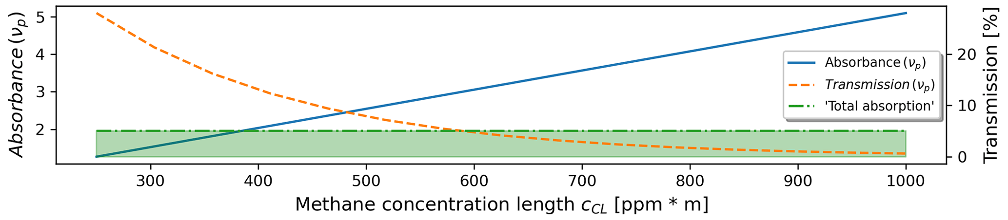
Figure 1The absorbance of the peak wave number νp=3067.28 cm−1 is plotted in blue, the transmission is drawn in orange, and the green marked area shows the section of total absorption. Here, less than 5 % of the laser light is transmitted through the gas.
In this work, a real-time OGI camera with active illumination is realized. A tuneable single-mode distributed-feedback (DFB) interband cascade laser (ICL) at a wavelength of around 3260 nm from nanoplus is used as the illumination source. Within the emission range of the laser (with 25 mW optical power), some of the largest rovibrational CH4 absorption lines can be accessed. This enables a very high sensitivity for methane detection. Wavelength stability is assured using a methane-filled reference cell, illuminated with less than 1 % of the laser light. An elaborated mid-wave infrared (MWIR) camera with an integrated Stirling cooler is used for the light detection (ImageIR 8300 from InfraTec, shown in black in Fig. 2). The laser and camera are synchronized by a redpitaya STEMlab 125-10 single-board computer with a field-programmable gate array (FPGA). The streaming of real-time methane quantification images as well as their visualization is, at the current state, realized with a frame rate of 15 Hz. Additionally, an Intel RealSense D430 camera simultaneously streams RGB data.
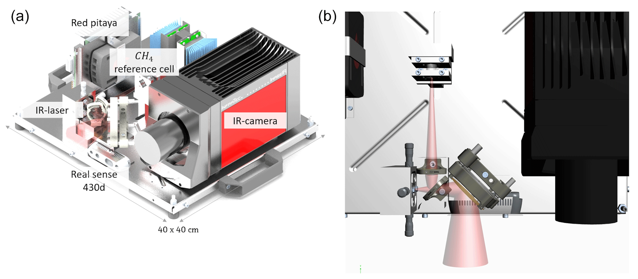
Figure 2The setup of the real-time active-gas camera. Panel (a) presents the main components, including the infrared camera and the laser (whose beam is sketched in red), and panel (b) provides a view from the top of the instrument. Less than 1 % of the laser's light is coupled out for locking its wavelength on the target gas absorption line.
The conducted measurements that will be described in the following section contain two different experimental setups: the validation measurements (described in Sect. 4.1) are conducted through a gas reference cell, as shown in Fig. 3, and the visualization of the gas leak (in Sect. 4.2) is done on an artificial open gas leak, as seen in Fig. 7.

Figure 3(a) A sketch of the experimental setup to validate the measured concentration length (cCL) by varying the methane reference concentration (i), by varying the emissivities of the reflective element (ii), and by varying the distance between the reflective element and the camera (iii). In panel (b), the laser drive current is plotted vs. time. Within the first section, the laser drive current is set below the lasing threshold of the ICL; the second section drives the laser wave number “beside the absorption line” ν0; and the third section sets the laser wave number on the absorption line, νp. The ramp in the third section is for the wavelength lock of the laser. (c) The measured intensity for an exemplary pixel is plotted synchronously. The dashed line sketches the intensity if no gas is present, and the solid line shape sketches the gas absorption if gas is present below atmospheric pressures.
4.1 Concentration length validation
To validate the CL measurements, a test setup with a known gas concentration was created. This was realized by using a gas cell with a known optical path length and letting a constant controlled gas flow of methane and air pass through it. The experimental setup is sketched in Fig. 3. The stability of the algorithm was validated against three influences:
-
The distance to the reflective element was varied between 40 and 400 cm. The concentration length was then validated on the metal reflective element.
-
A variation in the reference CLs was achieved by diluting pure methane with air using mass flow controllers. The large dilution resulted in quite large uncertainties of 4 % for the adjusted CLs. Only for the 30 ppm m measurement could a calibrated test gas be used, so the uncertainty is much lower for this concentration. CLs between 2 and 293 ppm m were set.
-
Finally, varying reflecting elements were investigated on a constant reference CL. Emissivities between 0.4 and 0.95 were set. Details on their determination are given in the Appendix A.
4.2 Visualizing gas leakages
The main application of OGI cameras is the visualization and quantification of gas leaks. To prove the concept for the quantification of gas leaks, a leak with a fixed methane mass flow of 40 mL min−1 escaping a tube with an inner diameter of 2 mm was filmed using the active-gas camera at a 2 m distance. The gas leak was additionally moved before the reflective element to simulate moving objects that might occur in real-world scenarios. The recorded video, showing the real-time streams of the camera, can be downloaded from https://doi.org/10.5446/59364 (Bergau, 2022). The top-left panel in the video shows the IR image, and the top-right panel shows the IR image with the gas cloud overlaid in blue. Additionally, the masked-out objects (see Sect. 5.2) are shown using a red overlay. In the bottom-left panel of the video, an RGB image is shown, and the bottom-right panel displays the gas cloud (in ppm m).
5.1 Generating gas images
To extract the gas CL from the Beer–Lambert absorption law, knowledge on the back-scattered intensity with and without absorption as well as a background (BG) correction are needed. This is done by recording a batch of three single images. For clarification, this process is sketched in Fig. 3. Briefly, a background image (FBG) with the laser turned off, an image with the laser tuned “beside the absorption line” (FOFF), and an image with the laser tuned “on top of the absorption line” (FON) are required. The absorbance (A) is then obtained in a pixel-wise manner using Eq. (2), which reads in terms of images, as follows: . As the laser intensity scales with the wavelength, image (FOFF) is upscaled by 19 % to match the intensity of image (FON) in the case of no gas.
5.2 Moving objects
The previously described method for infrared imaging spectroscopy works well for nonmoving camera and image scenarios. As soon as objects move in the scene, parts of them will be recognized as a false gas signal in the quotient image (compare Eq. 2). To avoid this, the applied algorithm makes use of the background image that is recorded in every batch to mask out the incorrect information. Taking two sequential background images, a simple two-image frame difference algorithm finds the false information along the object trajectories, and incorrect information due to moving objects is suppressed. This procedure is sketched in Fig. 4. Thus, a faster camera as well as an increasing distance between the camera and the moving object reduce the masked-out area.
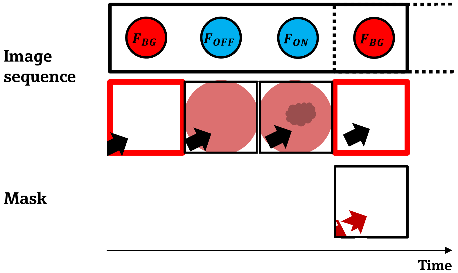
Figure 4Sketch of the two-image frame difference that is applied to subsequent background images (FBG). A mask is gained that is used to get rid of incorrect CL information due to moving objects or reflections. The black arrow represents an object moving through the camera's field of view.
6.1 Concentration length validation
The results of the CL validation are shown in Fig. 5. The distance variation (Fig. 5a) shows three notable effects. The first effect is the rising trend in the measured values. This could be explained by the atmospheric methane in the gas laboratory air. A linear fit yields a slope of 13.68 ppm. As the camera always measures the gas laboratory air twice, with the laser light going back and forth, this corresponds to a quite realistic methane concentration of ∼6.8 ppm in the laboratory. The second effect is that the extrapolation of the linear fit to 0 m underestimates the true CL that was set in the reference cell by ∼20 ppm m. This offset could be a statistical effect, combining the estimated methane slope of 13.7±1.0, the uncertainty of the reference system, and the linearity offset of the camera setup described below. The third effect is that an increasing distance results in a weaker laser reflection signal. The effect on the noise is seen in the rising error bars and is further discussed at the end of this section. The variation in the emissivity (Fig. 5b) shows that lower signal leads to a higher noise. Besides this, the measured CL values can be considered independent of the reflective element. The variation in the reference concentration length (Fig. 5c) denotes the linearity of this spectroscopic system as (95±3) %. Considering the real-time approach of the algorithm, which only considers the absorption line at two points, this is considered satisfying.

Figure 5The measured concentration lengths (cCL) are validated against three influences: (a) the effect of varying the distance between camera and the metal reflective element (ε=0.4), where the slope of the linear fit may show twice the methane (because the light is absorbed on the way to the target and back) in the gas laboratory (∼6.8 ppm); (b) the effect of reflective elements with different emissivities; and (c) the effect of varying the reference methane concentration at a distance of 40 cm from the metal reflective element, where the linearity is off by 5 %. In panels (a) and (b), the blue line shows the methane concentration length in the reference cell, and the light blue area denotes its uncertainty.
A detailed look at the sources of noise is justified in this setup. All CL validation measurements evaluate three-dimensional concentration image stacks; thus, noise can be considered in the spatial direction (within one image) and/or in the temporal direction (along one pixel across many images). It should be noted that each concentration image consists of three subsequent images; hence, the spatial noise is also influenced by time effects, leading to a correlation of both noise types. Sources of noise might consist of detector pixel noise, comprising spatially varying speckle effects that occur through laser tuning and through vibration of the camera laser system due to the Stirling cooler in the IR camera. Detector pixel noise was found to be in the order of and was neglected. Therefore, the background images are considered to be noise-free, whereas other noise sources sum to a factor ΔI for each image. Thus, noise (N) is , leading to a stronger noise influence for lower laser intensities I(νp). The spatial noise was found to typically dominate over the temporal noise. Thus, a Gaussian blur filter was applied. Its effect on the spatial noise is shown in Fig. 6. As a compromise between the spatial resolution of the concentration image and a reduction of noise, σgaus was chosen to be 5 px. At a typical measuring distance of 1 m, this corresponds to a spatial blur of 3.1 mm. The spatial noise on a homogeneous concentration after applying the Gaussian filter is 3 ppm m. This is added to the concentration length noise (which is determined in the time dimension) in all measurements as a systematic error.
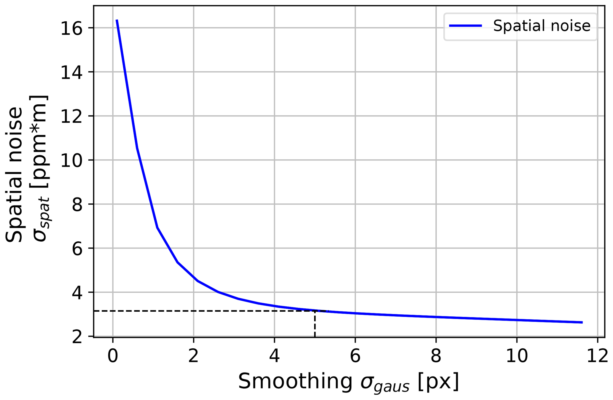
Figure 6The effect of smoothing the concentration images with a Gaussian blur filter with a standard deviation σgaus on the spatial noise is shown. The distance for the concentration image was 100 cm, and the emissivity of the reflective element was 0.4. As a compromise between spatial resolution and noise reduction, σgaus=5 px was chosen. At a typical imaging distance of 100 cm was used, which corresponds to 3.1 mm.
6.2 Visualizing gas leakages
Figure 7 presents 15 exemplary frames from a gas video, showing a 40 mL min−1 methane jet leaking out of a tube with an inner diameter of 2 mm. The leak is moved by hand in order to show the feasibility of the frame-difference approach with respect to dealing with moving objects. The infrared information is visualized in grayscale, and the methane plume is overlaid in blue. The opacity of the methane plume is a measure of the CL. The red overlay shows the mask filtering out moving objects or, more generally, moving infrared signal, as seen in frames 62 or 73 where the thermal reflection signal is strong and is masked out as well. It should be noted that the set flow rate of 40 mL min−1 does not represent the lower detection limit of the system. Instead, it was chosen as it was the lower limit of the used mass flow controller in this setup (a Brooks FR2000 2A12).

Figure 7A total of 15 exemplary frames of a gas video are plotted (recorded with the active OGI camera). The infrared information is shown in grayscale. The methane stream is overlaid in blue, and its opacity accounts for the CL (in units of ppm m−1). The red marked parts show where the frame-difference mask suppresses incorrect CL information. The video is available for download (see the Video supplement section for more information).
As derived in Sect. 2, concentration lengths above ∼600 ppm m saturate the active camera due to the total absorption of the laser light. Thus, the larger gas flows (in the range of L min−1) that passive OGI cameras need due to their low sensitivity, as shown in the publications of Wang et al. (2022), are not reasonable for a comparison and should be treated as different application scenarios (Strahl et al., 2021). The strong sensitivity of this approach could make it suitable for the visualization of more toxic gases, e.g., ammonia.
In this work, a laser-based setup and a method for a sensitive real-time methane visualization based on a three-image concentration calculation is realized. Methane concentration length (CL) measurements are carried out and validated against varying distances, reflective elements, and concentration lengths. The designed system shows a linearity of 5 % without temporal averaging and a frame rate of 15 Hz.
At a flow of 40 mL min−1, a free-floating methane leak is visualized and quantified at a distance of 2 m. An adapted frame-difference approach is introduced to avoid incorrect CL information due to moving objects.
Based on this approach, further post-processing steps are possible to gain additional information. One example, using the accurate CL information, is an improved mass flow estimation compared with passive OGI cameras. Sensor fusion with visible and depth data could increase the comprehensibility of the visualizations and could also be used to correct the measured leak column concentrations of environmental methane by estimating the distance between the leak and the camera.
Practical use of the active approach still needs to be proven on poorly reflecting elements for larger distances. A system setup that may have potential in this regard is a “methane laser scanner”, which may increase the signal-to-noise ratio significantly by using a focused laser beam that is rasterized over the field of view, similar to the approach being developed in the “SPLICE” project (Titchener et al., 2022).
The emissivity values of the different reflective-element materials were estimated by heating them to 48.5 ∘C. This temperature was checked with a contact temperature sensor. Next, the same materials were recorded with the infrared camera. The emissivity values were now determined using the IRBIS 3.1 software provided by the camera manufacturer (InfraTec).
Thus, the determination is within the spectral range of the infrared camera (2–5.7 µm). For the measurements, it is assumed to be the same at the measuring wavelength of 3.2 µm. The uncertainty is estimated by measuring the emissivity range along each single reflective-element material. The emissivity (ϵ) in thermal equilibrium can be used as an estimator for the reflectivity (R) assuming opaque objects and Kirchhoff's law:
The Bronkhorst EL-FLOW Prestige mass flow controller, used to set the gas flows, is calibrated on nitrogen. When using other gases, a conversion factor (γ) must be applied to the flow rate (fi) for the gas of molecules i:
The concentration length cCL within the gas cell is given as follows:
Here, si denotes the absolute 1σ uncertainty of the measured quantity i. It is achieved as follows:
-
, based on the manual (Bronkhorst®, 2022).
-
sf=0.1 %, as the uncertainty of the flow depends on environmental conditions. The estimated 0.1 % relative error is based on a recommendation from the manufacturer. fair was set to 1 L min−1, whereas the methane flow was adjusted to obtain the required concentration.
-
sl=0.1 mm, which was estimated because the reference cell is designed with tilted antireflective windows
The code can be made available from the authors upon reasonable request.
The data can be made available from the authors upon reasonable request.
A video showing the recording of a 40 mL min−1 methane leak using the active OGI camera is presented at https://doi.org/10.5446/59364 (Bergau, 2022). The video streams multiple images simultaneously: an infrared image; an RGB image; the gas concentration lengths (CLs); and an overlay of the CLs, the infrared image, and the moving object mask.
MB and BS conceptualized the study. The experiments as well as the generation and evaluation of the results were undertaken by MB. TS helped with the methodology. BS and JW supervised the study.
The contact author has declared that none of the authors has any competing interests.
Publisher's note: Copernicus Publications remains neutral with regard to jurisdictional claims in published maps and institutional affiliations.
This article is part of the special issue “Dresden Sensor Symposium DSS 2021”. It is a result of the “15. Dresdner Sensor-Symposium”, Dresden, Germany, 6–8 December 2021.
This research has been supported by the Bundesministerium für Bildung und Forschung (grant no. FKZ:13N15189).
This paper was edited by Udo Weimar and reviewed by three anonymous referees.
Aldhafeeri, T., Tran, M.-K., Vrolyk, R., Pope, M., and Fowler, M.: A Review of Methane Gas Detection Sensors: Recent Developments and Future Perspectives, Inventions, 5, 28, https://doi.org/10.3390/inventions5030028, 2020.
Bergau, M.: Visualization of a 40ml/min methane leak using an active OGI camera, TIB AV-Portal [video], https://doi.org/10.5446/59364, 2022.
Bronkhorst®: Instruction Manual EL-FLOW®Prestige, Doc. no.: 9.17.084 rev. R, https://www.bronkhorst.com/getmedia/e6957a9f-8452-4005-b4f7-993ca67624e6/917084-Manual-EL-FLOW-Prestige.pdf (last access: 18 January 2023), 2022.
Gordon, I. E., Rothman, L. S., Hargreaves, R. J., et al.: The HITRAN2020 molecular spectroscopic database, J. Quant. Spectrosc. Ra., 277, 107949, https://doi.org/10.1016/j.jqsrt.2021.107949, 2022.
Iseki, T., Tai, H., and Kimura, K.: A portable remote methane sensor using a tunable diode laser, Meas. Sci. Technol., 11, 594–602, https://doi.org/10.1088/0957-0233/11/6/302, 2000.
Li, J., Yu, Z., Du, Z., Ji, Y., and Liu, C.: Standoff Chemical Detection Using Laser Absorption Spectroscopy: A Review, Remote Sensing, 12, 2771, https://doi.org/10.3390/rs12172771, 2020.
Masson-Delmotte, V., Zhai, P., and Pirani, S. L.: IPCC: Climate Change 2021: The Physical Science Basis. Contribution of Working Group I to the Sixth Assessment Report of the Intergovernmental Panel on Climate Change, Cambridge University Press, 2021.
Nisbet, E. G., Manning, M. R., Dlugokencky, E. J., Fisher, R. E., Lowry, D., Michel, S. E., Myhre, C. L., Platt, S. M., Allen, G., Bousquet, P., Brownlow, R., Cain, M., France, J. L., Hermansen, O., Hossaini, R., Jones, A. E., Levin, I., Manning, A. C., Myhre, G., Pyle, J. A., Vaughn, B. H., Warwick, N. J., and White, J. W. C.: Very Strong Atmospheric Methane Growth in the 4 Years 2014–2017: Implications for the Paris Agreement, Global Biogeochem. Cy., 33, 318–342, https://doi.org/10.1029/2018GB006009, 2019.
Nutt, K. J., Hempler, N., Maker, G. T., Malcolm, G. P. A., Padgett, M. J., and Gibson, G. M.: Developing a portable gas imaging camera using highly tunable active-illumination and computer vision, Opt. Express, 28, 18566, https://doi.org/10.1364/OE.389634, 2020.
Ravikumar, A. P., Wang, J., and Brandt, A. R.: Are Optical Gas Imaging Technologies Effective For Methane Leak Detection?, Environ. Sci. Technol., 51, 718–724, https://doi.org/10.1021/acs.est.6b03906, 2017.
Ravikumar, A. P., Wang, J., McGuire, M., Bell, C. S., Zimmerle, D., and Brandt, A. R.: “Good versus Good Enough?” Empirical Tests of Methane Leak Detection Sensitivity of a Commercial Infrared Camera, Environ. Sci. Technol., 52, 2368–2374, https://doi.org/10.1021/acs.est.7b04945, 2018.
Song, K. and Jung, E. C.: Recent Developments in Modulation Spectroscopy for Trace Gas Detection Using Tunable Diode Lasers, Appl. Spectrosc. Rev., 38, 395–432, https://doi.org/10.1081/ASR-120026329, 2003.
Strahl, T., Herbst, J., Lambrecht, A., Maier, E., Steinebrunner, J., and Woellenstein, J.: Methane leak detection by tunable laserspectroscopy and mid-infrared imaging, Appl. Optics, 60, C68–C75, https://doi.org/10.1364/AO.419942, 2021.
Titchener, J., Millington-Smith, D., Goldsack, C., Harrison, G., Dunning, A., Ai, X., and Reed, M.: Single photon Lidar gas imagers for practical and widespread continuous methane monitoring, Appl. Energ., 306, 118086, https://doi.org/10.1016/j.apenergy.2021.118086, 2022.
Wang, J., Ji, J., Ravikumar, A. P., Savarese, S., and Brandt, A. R.: VideoGasNet: Deep learning for natural gas methane leak classification using an infrared camera, Energy, 238, 121516, https://doi.org/10.1016/j.energy.2021.121516, 2022.
Zeng, Y. and Morris, J.: Detection limits of optical gas imagers as a function of temperature differential and distance, J. Air Waste Manage., 69, 351–361, https://doi.org/10.1080/10962247.2018.1540366, 2019.
- Abstract
- Introduction
- Concentration length (CL) calculation
- The setup of the active OGI camera
- Measurements
- Methods
- Results and discussion
- Conclusion and outlook
- Appendix A: Emissivity estimation
- Appendix B: Concentration validation
- Code availability
- Data availability
- Video supplement
- Author contributions
- Competing interests
- Disclaimer
- Special issue statement
- Financial support
- Review statement
- References