the Creative Commons Attribution 4.0 License.
the Creative Commons Attribution 4.0 License.
 | 13 Mar 2023
Energy analysis of a wireless sensor node powered by a Wiegand sensor
Jonas Wiegner
Hanno Volker
Fabian Mainz
Andreas Backes
Michael Loeken
This article describes an Internet of things (IoT) sensing device with a wireless interface which is powered by the energy-harvesting method of the Wiegand effect. The Wiegand effect, in contrast to continuous sources like photovoltaic or thermal harvesters, provides small amounts of energy discontinuously in pulsed mode. To enable an energy-self-sufficient operation of the sensing device with this pulsed energy source, the output energy of the Wiegand generator is maximized. This energy is used to power up the system and to acquire and process data like position, temperature or other resistively measurable quantities as well as transmit these data via an ultra-low-power ultra-wideband (UWB) data transmitter. A proof-of-concept system was built to prove the feasibility of the approach. The energy consumption of the system during start-up was analysed, traced back in detail to the individual components, compared to the generated energy and processed to identify further optimization options. Based on the proof of concept, an application prototype was developed.
- Article
(1469 KB) - Full-text XML
- BibTeX
- EndNote


The continuing growth of the Internet-of-things (IoT) market not only increases productivity and opens up new business models but also places new requirements on the involved devices. These requirements address reliability, precision, autonomy and maintenance. Prominent participants in the IoT are ubiquitous sensing devices that do not rely on cable connections and can therefore be placed at any spot. Hence, the usage of energy available in the environment (“energy harvesting”) to power sensor technology and wireless information transmission is of paramount importance.
In the following, a proof-of-concept system powered from a Wiegand generator and using off-the-shelf components like a microcontroller (MCU) is designed. It is operated in pulsed or “one-shot” mode and used to not only acquire but also transmit the data wirelessly. As the time between two pulses may be very long, no power can be harvested in the meantime, and the system has to start up for every single event, including charging of the capacitors and initialization processes. Accordingly, the energy needed for the start-up plays a crucial role in this kind of single-event operation. While low-power operation modes of MCUs are precisely specified in data sheets, the start-up energy is, in general, not specified by the suppliers. It depends on the power supply circuit, the MCU itself including the capacitors and the clock speed, and other parameters. For use in single-event applications, like the Wiegand generator, the start-up must be analysed carefully to enable the required operations.
As one of many possible applications, the system is then integrated into a physical prototype comprising a window-opening sensor.
Some prominent approaches for energy harvesting include photovoltaic, thermoelectric and radiofrequency (RF) harvesting (Maurya et al., 2012), but each of them relies on the availability of the respective energy forms. In general, these sources provide the output energy continuously. When moving parts are involved, induction-based energy harvesters are another well-established approach to harvest a part of the motion energy. The drawback of induction-based energy harvesters is the minimum speed of the moving parts that is needed to generate sufficiently high voltage pulses in a given pickup coil and hence provide sufficient energy output to a given resistive load.
To overcome the low-speed problem for inductive harvesters, spring-based solutions can be used to guarantee a sufficiently high speed of the moving part generating the desired energy output. This solution comes at the price of mechanical wear and hence decreased maintainability. By contrast, the Wiegand effect provides a contactless solution to the problem without mechanical support by springs (Wiegand and Velinsky, 2004).
Wiegand effect
Wiegand sensors, which are well established in low-power applications such as revolution counters in rotary encoders (Mehnert and Theil, 2004) or flow meters, make use of the anisotropic magnetic properties of a specially treated thin wire of specific ferromagnetic alloys (such as vicalloy). Due to the magnetic anisotropy, the wire is preferably magnetized in one of the two directions along the wire axis (Abe et al., 1997). No matter how slow the external magnetic field changes, the transition between these two bi-stable states, often referred to as the macroscopic Barkhausen effect, takes place almost instantaneously (Abe et al., 1998; Huening and Backes, 2020). It is associated with a release of magnetic energy that can be picked up as induction voltage in a surrounding coil.
Continuous harvesting systems (e.g. photovoltaic or thermoelectric) are designed and optimized to continuously provide output energy. Albeit low, the energy is sufficient to charge an energy storage element and to maintain a minimum system voltage to operate the components like sensors and microcontrollers (MCU) continuously. For this kind of low-energy operation, MCUs provide dedicated operation modes like deep-sleep or standby modes to reduce the power consumption as far as possible. More energy-intensive operations like reading out sensors or data storage are executed from time to time when sufficient energy is harvested.
In contrast, event-based harvesters like the Wiegand generator can provide a specific amount of energy at one stroke; for commercial Wiegand sensors, the energy is lower than 200 nJ. They can also be operated in a mode of periodic excitation (Takahashi et al., 2018). Nevertheless, if the system is designed accordingly, this single amount of energy will be sufficient to perform a simple operation (such as reading a Hall sensor: Takemura et al., 2017).
To operate more complex systems, the energy of available Wiegand sensors is by far not sufficient. Hence, the Wiegand harvester has to be optimized to increase the output energy drastically. Another challenge in pulsed operation mode is that no power is provided between events. Hence, at the beginning of the operation all capacitors are discharged, and all information is only available from non-volatile memory components. For this discontinuous operation mode with system start-up from the off state with discharged capacitors, the low-power operation modes of MCUs are not a reliable indicator for the start-up energy. Therefore, the energy needed to start the system has to be analysed in detail and compared to the generated energy to enable the pulsed operation.
The impulse-radio ultra-wideband (IR-UWB) wireless technology transmits ultra-short electromagnetic pulses within a frequency range of 3–11 GHz. The shortness in time domain translates to a wide spectrum in the frequency domain. This results in a minimized spectral energy density, as the energy is spread over a wide spectrum. Therefore, the UWB signals just increase the general RF noise floor by a negligible amount, so the technology can coexist with narrowband (NWB) technologies in the same frequency range (Blázquez et al., 2005).
Besides the newly gained resource for data transmission, the UWB technology features additional benefits. A well-known example is the suitability for high-precision ranging via time-of-flight (ToF) measurements, making use of the precisely determinable timing of the pulses (Spark, 2020). The principle-related low power consumption is another advantage, as the transmitting power is only consumed by short pulses instead of a constantly powered frequency generators for NWB technology (Khajenasiri et al., 2015).
This results in the UWB technology being a promising candidate for the wireless transmission technology employed in a wireless sensor node supplied by energy harvesting from a Wiegand generator.
A proof-of-concept system like the one depicted in Fig. 3 (powered from a Wiegand generator and using off-the-shelf components) is designed to operate in pulsed mode and to acquire and transmit data wirelessly. As one of many possible applications, the system is then integrated into a physical prototype comprising a window-opening sensor.
4.1 Wiegand generator
Current commercial Wiegand sensors for position detection applications provide an energy output which does not exceed 200 nJ. By upscaling the sensor and adopting further optimizations to the Wiegand wire, the pickup coil and ferrite beads at its ends, this output can be increased drastically to about 6–8 µJ for a coil of 21 mm length and 7.5 mm diameter under otherwise optimal conditions even in the low-speed limit. This Wiegand generator shown alongside a conventional Wiegand sensor in Fig. 1 can be excited by the movement of two or more bar-shaped permanent magnets that are magnetized in alternating orientation along their cylindrical axis.

Figure 1Wiegand sensor for energy-self-sufficient motion sensing (top) and Wiegand generator (right).
4.2 Harvesting circuit
As the energy provided by the Wiegand generator is very low and just available in single-shot mode, the efficiency of the harvesting circuit is very important. Figure 2 shows the simple structure of the harvesting circuit. The output current of the Wiegand generator is rectified and charges a capacitor, from which the components of the digital circuit draw their power after sufficient energy has been harvested.
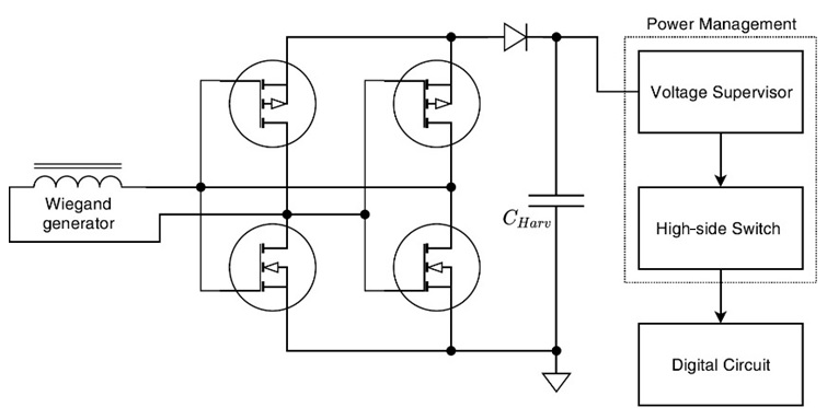
Figure 2Harvesting circuit supplying the digital circuit with energy from the Wiegand generator.
4.3 Digital circuit
The proof-of-concept system consists of the wireless sensor node (transmitter), powered by energy harvesting, and a UWB base station or IoT gateway (receiver), powered by an external source. The node shall be operated in a pulsed mode, where the Wiegand generator provides a specific energy pulse upon an external event, which shall be sufficient to start up the system, sample a sensor value and transmit this value via the UWB transceiver. The node's architecture (Fig. 3) contains a microcontroller unit (MCU), a 32 kHz oscillator needed for the UWB transceiver and the energy-harvesting circuit. Additionally, there is the possibility to connect an external sensor: either analogue and sampled by the MCU's analogue-to-digital converter (ADC) or a smart sensor connected via a digital interface to the MCU. As UWB transceiver, the SR1000 integrated circuit (IC) family, manufactured by SPARK Microsystems, is used. One key aspect of the SR1000 IC family is the focus on power-efficient data transmission, resulting in an outstanding low-power performance compared to other manufacturers and technologies (Spark, 2020).
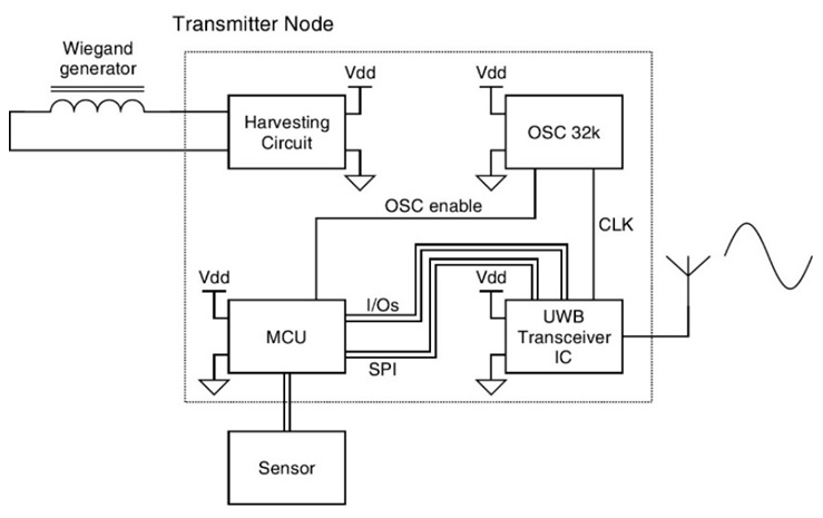
Figure 3Digital circuit containing the UWB transceiver, MCU, oscillator and an external sensor.
The SR1000 features a Serial Peripheral Interface (SPI) for communication and three mandatory I/O pins connected to the MCU. Shortly after voltage ramp-up, it can be configured via several registers and supplied with the data payload, in a way that it afterwards starts up and transmits autonomously without the need of further external communication. In the used configuration, the SR1000 needs around 5 ms between configuration via SPI and the successfully completed UWB transmission. One key adjustment to achieve this fast start-up is the use of an external 32 kHz oscillator with a fast-starting internal driver instead of the SR1000's internal crystal driver. Another important adjustment was to perform and store some necessary calibrations once and load them from the MCU's static memory at every start-up. The SR1000 UWB IC allows precise configurations of the radio signal, all of which affect the signal range or the energy consumption of the transmission (TX) back end differently. The signal transmission is susceptible to interference with surrounding objects, such that an implementation in a building may, on the one hand, result in reduced range. On the other hand, the antenna used was an omnidirectional wideband printed circuit board (PCB) antenna, and directed transmission is expected to enhance the range.
An MCU from STMicroelectronics' (ST's) ultra-low-power MCU series (STM32L0) is used. It is optimized for low-power applications and comes with some beneficial features for the design, e.g. different sleep modes; low-power clock generators; and, in particular, a fast and efficient start-up. This start-up behaviour will be analysed in the measurement section.
5.1 Wiegand output power
Figure 4 shows the generated energy output of a coil filled with ferromagnetic material (orange) in comparison to the energy of the Wiegand generator (green). In the zero-speed limit, the energy output of the inductive harvester approaches zero, even when referred to a single rotation instead of constant time span. Using the optimized Wiegand generator instead, the energy can be increased significantly to about 6–8 µJ under optimal conditions, even in the zero-speed limit or single-shot mode. At high frequencies, both systems behave rather similarly.

Figure 4Frequency dependency of energy output of the Wiegand effect compared to regular induction. A coil (8000 windings) is placed in an oscillating external magnetic field of 16 mT amplitude while the Joule heating power in a 3 kΩ resistor is measured. The coil is filled with a standard ferromagnetic material (orange) or Wiegand generator (green).
As opposed to the often very strict mounting tolerances (∼0.1 mm) of standard Wiegand sensors in motion-sensing applications (Posital, 2018), it turns out that the chosen configuration easily tolerates misalignments of the order of 1 mm (Fig. 5). Of course, other magnetic systems, e.g. rotating magnets, can be used for excitation of the Wiegand wire as well.
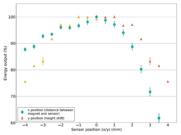
Figure 5Mounting tolerances of the magnets with respect to the Wiegand generator. Error of sensor position is within the symbols.
5.2 Power consumption
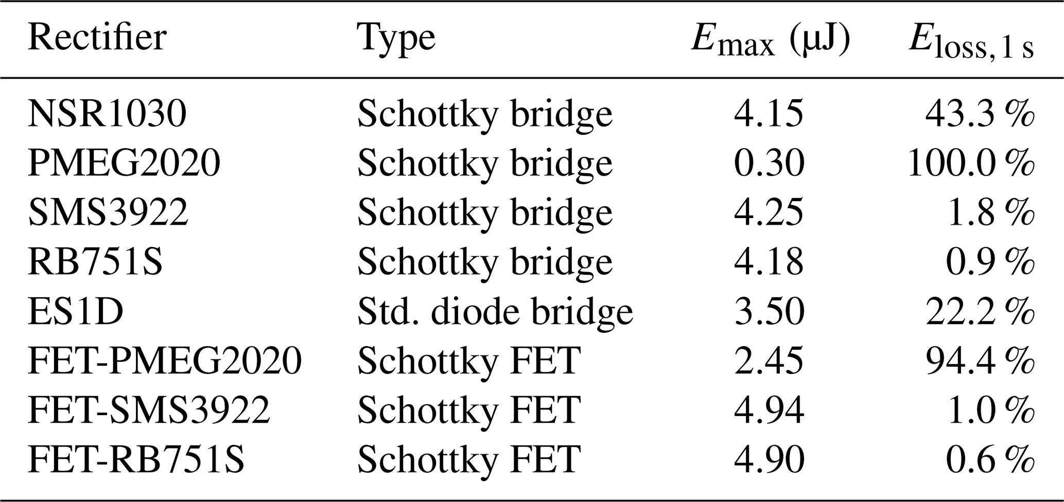
As the energy supplied by one Wiegand generator is not sufficient, two identical generators are used. While there are other possible configurations, the use of one rectifier per harvester turned out to reach the highest overall efficiency. Moreover, different rectifiers were tested for suitability with regard to forward conduction loss and blocking current. The rectifiers are supplied by a Wiegand harvester, charging a 1.02 µF capacitor, where the maximum energy, Emax, is calculated from the maximum voltage at the capacitor. Eloss,1 s designates the energy loss by the reverse current within 1 s after the maximum voltage occurred.
The use of a field-effect transistor (FET) configuration (Table 1) instead of a diode bridge rectifier leads to reduced forward losses due to the reduced voltage drop of only one diode and a better blocking current. The SMS3922 and RB751S Schottky diodes, which were chosen due to their state-of-the-art performance concerning the forward voltage drop and reverse current, outperformed the other diodes. For the prototype, the FET-RB751S rectifier is used.
Table 1Comparison of rectifier performance for various configurations and diode types.
The size of the harvesting capacitor has a major influence on the initial voltage and thus the efficiency of the generating system (Wiegand harvester, rectifier) and consuming system (MCU, UWB IC, etc.). To further evaluate and optimize the energy efficiency, the consumption of the circuit is precisely simulated as a model. As the output power of the Wiegand generator is also electrically modelled, this allows for a precise model-in-the-loop (MIL) simulation of the whole prototype circuit. This benefits with a better understanding of where avoidable losses occur and how to dimension relevant components like the harvesting capacitor. In conclusion, the best fit for the harvesting capacitor was found with a capacitance of 3.3 µF, which is therefore used to build the prototype.
Power management is required to ensure that sufficient energy has been harvested in the capacitor to perform the start-up and transmission cycle. It is realized with a voltage supervisor IC and an optimized discrete high-side switch circuit.
The measurement setup shown in Fig. 6 is used to measure and evaluate the power consumption of the three main components: MCU, OSC32k and SR1000 (UWB transceiver IC). The harvesting capacitor is manually charged up to a voltage of 2.7 V by an external power source by temporary closing the leftwards switch. The start-up and transmit cycle is started by closing the rightward switch, supplying the components with voltage from the capacitor. Three current amplifiers are connected to the components in a low-side configuration, measuring the current flow from the components. For the measurements, the system is running at 4 MHz and is configured to transfer 4 B (bytes) of random data.
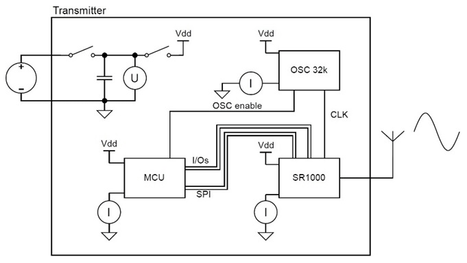
Figure 7 depicts the measurement of current, I, and voltage, U, during system start-up, where I is calculated by adding the three currents of the current amplifiers. The voltage of the harvesting capacitor drops from 2.7 V at the beginning to approximately 2.0 V at the end of the cycle as the energy is drawn from it. The corresponding consumed energy is calculated by integrating the consumed power. The energies given in Fig. 7 are calculated until the system finishes transmission and until all components are in standby or sleep mode.
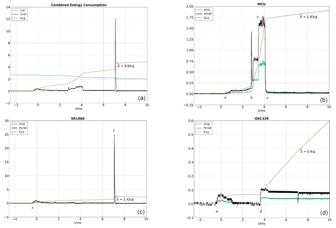
The complete system energy consumption is distributed over the three main components as shown in Fig. 7 (top left). The different phases of start-up are marked in the current and energy diagram of the MCU and the SR1000. The rightwards switch of the capacitor is closed at label a, supplying the components with voltage. At label b, the MCU is starting up with a reduced clock frequency of 2 MHz. The application code execution phase with the MCU running at 4 MHz is marked with label c, approximately doubling the current consumption. In this phase, the OSC32k is enabled (label d), and the configuration and transmission data are transmitted to the SR1000 IC via SPI. Subsequently, the MCU switches to standby mode (label e), and the SR1000 is starting up. The current peak at label f is caused by the start of the internal DC–DC converter of the SR1000, superimposed by the radio-transmitting current 500 ns later. This event designates the end of the start-up transmit cycle of the sensor node.
5.3 Correlation of power generation and power consumption
The summarized analysis of the energy distribution introduced by different components and phenomena as described in the previous section is shown in Fig. 8. The Wiegand generator in the used configuration with two coils and two magnetic inversions per triggering event is theoretically capable of generating 29.6 µJ, which corresponds to 100 % of energy yield. As this energy was measured in a homogeneous magnetic field and with an optimal resistive load of 3 kΩ, the energy yield in a more realistic scenario differs. The optimized rectifier is accountable for 26.7 % less energy yield on the resistive load, while the use of the 3.3 µF capacitance reduces the energy by a further 7.0 % compared to the resistor.
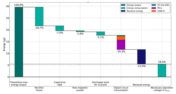
The use of moving permanent bar magnets to excite the generator accounts for an almost negligible reduction of the useable energy of 1.6 % compared to the homogeneous magnetic field. For the measurement cycle, the harvesting process is stretched over a period of 2 s, simulating a worst-case scenario of very slow movement, during which a constant discharge of the capacitor occurs. This happens due to the reverse current of the rectifier and the supply current to the voltage supervisor, and it is responsible for an additional loss of 5.1 %.
The digital circuit consumes in total only 15.9 % of the energy, which can be further divided to 6.1 % for the MCU, 8.4 % for the UWB IC and 1.4 % for the oscillator. Only a minor portion of energy is consumed for the transmission compared to the initial start-up energy and other losses. Therefore, a further energy reduction of the radio transmitter, which would bring disadvantages in terms of range or data payload, seems to be a low-priority step. In contrast, a new implementation of the UWB functionalities, meeting the requirements of the pulsed-operation transmit-only IC, would result in elimination of redundant IC-internal components, and this is expected to achieve a much higher efficiency increase.
As the digital circuit needs at least a voltage of 1.8 V to operate, the harvesting capacitor needs to hold the corresponding charge or energy until the cycle is finished. Therefore, another 18.4 % of the possible energy cannot be used for the application.
On average, a residual energy of 21 % (7.5 µJ) remains unused but usable. This is partly necessary as a safety margin, but it may be also used for additional sensor readouts, further MCU calculation for stability and security, or increased UWB payload data transfer.
A physical prototype comprising a window sensor was built for presentation purposes. The sensor node consists of the prototype PCB with a UWB PCB antenna (label a); two Wiegand generators (labels b), mounted to the moving window; and the magnet assembly containing three magnets, mounted to the frame (label c) (Fig. 9). Via a connector, various sensor devices can be connected, and a few examples are stated in Table 2.
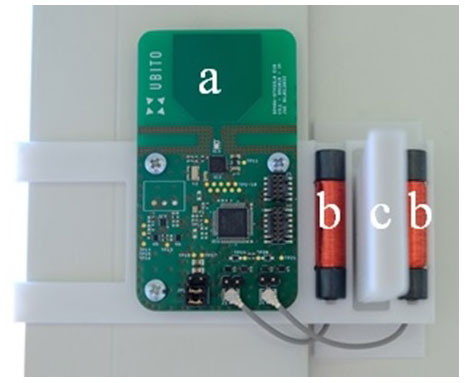
Table 2Sensor devices evaluated with the prototype and their additional energy consumption.

The design is able to sample and transmit the sensor data each time the window is opened or closed, which are then displayed in the receiving UWB base station.
This paper presents the design and evaluation of a novel sensor node powered by energy harvesting using the Wiegand effect.
Both the output energy of the Wiegand generator and the power consumption of the system, in particular the start-up, were analysed in detail. The prototype proves the concept of using energy harvesting based on the Wiegand effect to power a circuit that performs data acquisition, processing, and wireless transmission in a pulsed operating mode.
Obvious applications of such a system include door- or window-opening sensors for smart-home applications or industrial logistic automatization. The ability to sense other physical properties also makes this idea suitable for monitoring applications in the vicinity of moving parts (e.g. pumps, windmills, turbines, wheels, assembly belts, etc.). This can result in a novel plug-and-play solution for situations where a power supply via cable, battery or other energy-harvesting technology is impossible or uneconomical.
It should be emphasized that the prototype has been built up from off-the-shelf low-power electronic components, some of which are more optimized for applications with continuous energy harvesting rather than pulsed operation.
The findings elucidate the potential for further optimization of energy efficiency if dedicated parts were to be developed and employed. For large-volume applications, it might be worthwhile to develop dedicated ICs that integrate rectifier, power management, sensor, data processing and wireless transmission functions. Enhancing the energy efficiency and thus reducing the energy requirements would allow for size reduction with respect to the Wiegand generator, leading to an additional decrease in size beyond that of the circuit integration.
To produce its full energy output, the current design using two Wiegand generators still requires a finite change, ΔH, of the external magnetic field and hence a finite range of movement, which therefore needs to take place in a limited time span to avoid exceedingly large losses due to self-discharge. Several approaches are currently being investigated which may help to overcome this limitation.
The implementation of the microcontroller can be provided for reproducing the experiments for a similar sensor node. The scripts for analysing and visualizing the data can be provided on request (huening@fh-aachen.de).
All experimental data are available from the corresponding author and can be provided on request (huening@fh-aachen.de).
HV, ML and FH derived the research question; HV and FH developed the concept and initial design of the Wiegand generator; AB prepared the Wiegand wires and supported the sensor design. JW and FM designed the experimental setup and prototype and performed the measurements and analysis. HV, JW and FH prepared the article with contributions from all co-authors.
The contact author has declared that none of the authors has any competing interests.
Publisher's note: Copernicus Publications remains neutral with regard to jurisdictional claims in published maps and institutional affiliations.
This article is part of the special issue “Sensors and Measurement Systems 2022”. It is a result of the “Sensoren und Messsysteme 2022, 21. ITG/GMA-Fachtagung”, Nuremberg, Germany, 10–11 May 2022.
We gratefully acknowledge generous support by the Federal Ministry of Education and Research (BMBF) within the framework programme “Microelectronics from Germany – Driver of innovation for the digital economy” (contract no. 16ME0118). The results of the funded project are expected to soon enter the product portfolio of UBITO B.V. (part of the FRABA B.V. group).
Furthermore, we would like to thank Florian Hallermann and Biji Balakrishnan for fruitful discussions and support.
This research has been supported by the Bundesministerium für Bildung und Forschung (contract no. 16ME0118).
This paper was edited by Jürgen Wöllenstein and reviewed by two anonymous referees.
Abe, S., Matsushita, A., and Naoe, M.: Annealing and torsion stress effect on magnetic anisotropy and magnetostriction of Vicalloy fine wire, IEEE T. Magn., 33, 3916–3918, 1997.
Abe, S., Matsushita, A., and Naoe, M.: Dependence of large Barkhausen jump on length of a Vicalloy fine wire with torsion stress, IEEE T. Magn., 34, 1318–1320, 1998.
Blázquez, R., Lee, F., Wentzloff, D., Ginsberg, B., Powell, J., and Chandrakasan, A.: Direct Conversion Pulsed UWB Transceiver Architecture, Des. Aut. Test Europe, 3, 94–95, 2005.
Bosch: BMA400 – 3-axes ultra-low power accelerometer, Version 1.6, Bosch Sensortec GmbH, https://www.bosch-sensortec.com/products/motion-sensors/accelerometers/bma400/ (last access: 15 September 2022), 2021a.
Bosch: BMG250 – Low noise, low power triaxial gyroscope, Version 1.5, 2021b.
Huening, F. and Backes, A.: Direct Observation of Large Barkhausen Jump in Thin Vicalloy Wires, IEEE Magn. Lett., 11, 1–4, 2020.
Khajenasiri, I., Zhu, P., Verhelst, M., and Gielen, G.: A Low-Energy Ultra-Wideband Internet-of-Things Radio-System for Multi-Standard Smart-Home Energy Management, IEIE Transactions on Smart Processing and Computing, 4, 354–365, 2015.
Maurya, S., Sumam, P., and Maringati, R.: A Review of Energy Harvesting Techniques for WSN, Proc. Eighth Int. Conf. on Wireless Comm. and Sensor Networks, Naresuan University, Phitsanulok, Thailand, https://doi.org/10.13140/2.1.2713.1526, December 2012.
Mehnert, W. and Theil, T.: Positionsdetektor, Patent DE10259223B3, 2004.
Posital: Datasheet Wiegand wire sensor WS-WFS-4-U0, Version 20180220, 2018.
Sensirion: Datasheet SHT25 – Humidity and Temperature Sensor IC, Version 3, SENSIRION AG, 2014.
Spark: SPARK SR1000 UWB Transceiver White Paper – The Wireless Transceiver Reimagined, SPARK Microsystems International, https://www.sparkmicro.com/wp-content/uploads/2020/03/SMW001A3TheWirelessTransceiverReimagined_Final.pdf (last access: 15 September 2022), 2020.
Takahashi, K., Takebuchi, A., Yamada, T., and Takemura, Y.: Power supply for medical implants by Wiegand pulse generated from magnetic wire, J. Magn. Soc. Jpn., 42, 49–54, 2018.
Takemura, Y., Fujinaga, N., Takebuchi, A., and Yamada, T.: Batteryless Hall sensor operated by energy harvesting from a single Wiegand pulse, IEEE T. Magn., 53, 1–6, 2017.
Wiegand, J. R. and Velinsky, M.: Patent US3820090, 2004.