the Creative Commons Attribution 4.0 License.
the Creative Commons Attribution 4.0 License.
 | 26 Jan 2024
Laser-tracker-based reference measurement for geometric calibration of phase-measuring deflectometry with active display registration
Yann Sperling
Ralf Bernhard Bergmann
Phase-measuring deflectometry (PMD) with active display registration (ADR) is a ray-optics-based technique for the shape measurement of specular surfaces. To obtain quantitative results, the relative position of the cameras of the PMD–ADR setup needs to be determined by geometric calibration. Geometric calibration can be performed by inserting a planar mirror into the setup that brings all camera fields of view to overlap on an active pattern display. The mirror is tilted to multiple positions and each time the cameras capture the displayed images, which yields sufficient data to obtain the relative camera positions and the positions of the mirror. In this article, we give a more detailed description of PMD–ADR and its calibration. We also implement a laser-tracker-based reference method to measure the mirror positions and use its result to expose systematic errors in the geometric calibration.
- Article
(6663 KB) - Full-text XML
- BibTeX
- EndNote


Phase-measuring deflectometry (PMD) is a geometric-optics-based measurement technique for the robust noncontact full-field measurement of specular surfaces (Knauer et al., 2004). PMD measures the deflection of light on a surface under test (SUT) by finding a correspondence between the camera image plane and the surface of a display that is used as active pattern generator. Beside its application in surface inspection (Werling et al., 2009; Höfer et al., 2016) and deformation (Li et al., 2014) and figure measurement (Su et al., 2010), PMD is often used to measure the SUT shape (Zhang et al., 2021c). To obtain the shape, additional regularization information must be provided. Many methods of regularization have been proposed (Knauer et al., 2004; Petz, 2006; Li et al., 2012; Liu et al., 2017; Xu et al., 2019; Yue et al., 2020; Wang et al., 2021), which unfortunately often limit the setup geometry.
Additionally, the display surface deviates from often assumed planarity, which leads to shape measurement errors. Bartsch et al. (2019) determine display shape as part of geometric calibration, but it is difficult to obtain characterization of the full display surface. The display may also change due to thermal expansion or gravitational influence (Huang et al., 2015a, b). Petz et al. (2020) stabilize the display in their PMD setup and employ a pair of cameras to measure its shape. They obtain a remarkable accuracy of 1 µm over a 50 mm SUT diameter, even for strongly curved SUTs. Zhang et al. (2021a) use a camera pair and digital image correlation to actively register 3D points of the display and obtain regularization by moving the display to multiple positions. However, their setup is limited to the measurement of nearly flat samples.
As a method of regularization and a solution to the nonideal behavior of the display, Bartsch and Bergmann (2020) proposed PMD with active display registration (ADR), which directly registers the display surface 3D points, a method we recently implemented (Sperling and Bergmann, 2023). In this paper, we extend the theoretical and experimental description of PMD–ADR. As geometric calibration of the setup components is an important part of PMD (Huang et al., 2018), we also consider the impact of possible geometric calibration errors on the shape reconstruction. In PMD–ADR geometric calibration, the camera observes the display via reflection on a planar calibration mirror, from which geometric constraints about the setup can be derived. Besides the geometric constraints from the reflected rays, the mirror position may also be determined using reference markers applied to the mirror (Petz et al., 2020). In other contexts, a laser tracker has been used to measure the position of optical mirrors (Gallagher, 2003; Burge et al., 2007; Huang et al., 2015a), albeit at the danger of damaging the mirror (Huang et al., 2015b). In this paper, we implement a laser-tracker-based method to measure the mirror tilt during geometric calibration, without touching the mirror surface. The deviations of mirror positions determined by the tracker and determined by geometric calibration give rise to a discussion on their impact on shape reconstruction.
Figure 1 shows a schematic of the PMD–ADR setup. It contains a PMD setup, in which a camera (1) observes a display via reflection on the SUT. Additionally, two cameras (2 and 3) directly observe the display. Each camera records images with sinusoidal intensity distribution shown on the display. Using phase-shifting techniques (Huang et al., 2018), one can calculate a mapping between camera pixels and the phase; the phase is an encoding of the display surface by 2D coordinates in units of display pixels. The rays of vision of pixels of cameras 2 and 3 with corresponding phase values can be intersected, to obtain a mapping from phase values to 3D points. We reduce noise of the 3D points by fitting a 2D polynomial to them that parameterizes the display shape. The mapping is then interpolated to assign a 3D point to each camera 1 pixel. To measure the shape of an SUT, the display is moved to several distances. This yields multiple 3D points for each camera 1 pixel, through which a line can be fitted. By intersecting the line with the corresponding camera 1 ray of vision, a 3D point of the SUT is obtained. To reduce noise, a normal vector is determined from the angular bisector of the fitted line and the ray of vision. Integration of all normal vectors yields the SUT shape (Huang et al., 2017).
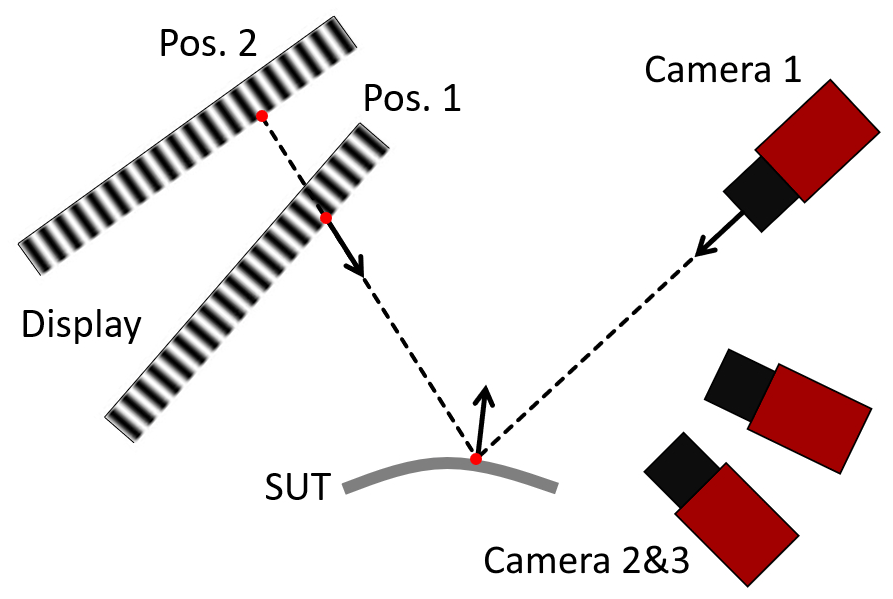
Figure 1Schematic of PMD–ADR measurement setup. To measure the SUT shape, the display is moved multiple distances. Using correspondences of phase values, multiple 3D points can be calculated and assigned to each camera 1 pixel. Intersecting the line fit through the points with the corresponding ray of vision yields a 3D point of the SUT.
Since the 3D points of the display surface are determined directly by cameras 2 and 3, PMD–ADR does not require calibration of the display position and shape. Therefore, only the cameras' rays of vision and their relative position need to be calibrated. We use the generic camera model and vision ray calibration (Bartsch et al., 2021) to calibrate the cameras. The generic camera model is suitable because in our case cameras 2 and 3 have wide-angle lenses, which might be inadequately modeled by many standard camera models (Bothe et al., 2010). Additionally, the relative position of cameras 2 and 3 need not be determined because they are calibrated in one common coordinate system. The remaining step is geometric calibration of the position of cameras 2 and 3 relative to camera 1.
2.1 Geometric calibration
To obtain the transformation T2&3,1 from the coordinate system OC2&3 of cameras 2 & 3 to the coordinate system OC1 of camera 1, a planar mirror is inserted into the setup which reflects light from the display to camera 1. The planar mirror is tilted to multiple positions and each time a phase measurement is being recorded by all three cameras. Starting with a guess of T2&3,1, we can calculate 3D points of the display surface in OC1 coordinates corresponding to camera 1 pixels, by the methods explained in Sect. 2. On the other hand, we can trace the camera 1 rays of vision to the 3D display points via reflection on the mirror, if we guess the mirror positions. The deviation between the traced rays and the 3D points now serves as the cost function. Minimization of the cost function with respect to the mirror positions and T2&3,1 yields the desired estimate of T2&3,1.
The cost function is a sum of squares of the minimal distances between each point and the corresponding reflected ray. Only a fraction of the data of all camera 1 pixels is used in the numeric calculation to reduce the computational effort. T2&3,1 is parameterized by a translation vector and three Euler angles. Each position of the planar mirror is parameterized by a “mirror vector” m: a plane is described by its minimal distance d from the origin and a unit vector e which is perpendicular to the plane and points towards it. By combining both variables into (Hesch et al., 2008), we have a one-to-one correspondence between planes and 3D vectors, ignoring planes that intersect the origin. We minimize the cost function with the MATLAB function fminunc (The MathWorks Inc., 2023a). Another option would have been a least-squares solver that, however, leads to a large Jacobian. The mirror vectors enter the cost function in a symmetric way via dot products, which simplifies calculation of analytical derivatives. Our approach is very similar to the general external camera calibration problem with a mirror (Hesch et al., 2008; Takahashi et al., 2012; Xu et al., 2019).
2.2 Measuring mirror positions with a laser tracker
A laser tracker is a device that tracks a reference target and measures its 3D coordinates (Muralikrishnan et al., 2016). We use a spherically mounted retroreflector (SMR) as target and nests in which the SMR can be placed with reproducible position. The nests are glued to the rear of the calibration mirror hold. By placing the SMR in each of these nests, the tracker can obtain the coordinates of points that are rigidly connected to the mirror.
During geometric calibration, the tracker measures the coordinates of the nests for each mirror position. To obtain the mirror vectors, we fit a plane through the coordinates of the nests. Although the nests generally do not lie on a plane, a rigid transformation of the nest coordinates will lead to the same transformation of the fit plane coordinates. Since the nests and therefore the fit plane are rigidly connected to the mirror, there exists a coordinate system OT such that, if we take the coordinates of the plane to be with respect to OT, the plane will coincide with the actual mirror surface and not the nests. We call OT the tracker coordinate system, although by its definition it will not coincide with the actual center of rotation of the tracker device. Therefore we can obtain the mirror vectors directly from the fit planes of the nests.
To compare the mirror positions obtained from the tracker with those from the geometric calibration, they need to be transformed to a common coordinate system. Figure 2 shows a schematic of how to transform mirror vectors from a coordinate system O to another O′. m is the mirror vector with respect to O, and m′ is the mirror vector with respect to O′. Imagine for a moment that the orientations of O and O′ are the same. Because of the collinearity of m and m′ we have for some α. But since the end points of both m and m′ lie on the plane, their difference vector is parallel to the plane and orthogonal to the mirror vector. Therefore . By inserting αm for m′, one obtains and hence . If the vectors are given in coordinate systems with different orientations, i.e., m is given in O, m′ and t are given in O′, and R is the coordinate rotation matrix from O to O′, we have to rotate m to O′ orientation and obtain
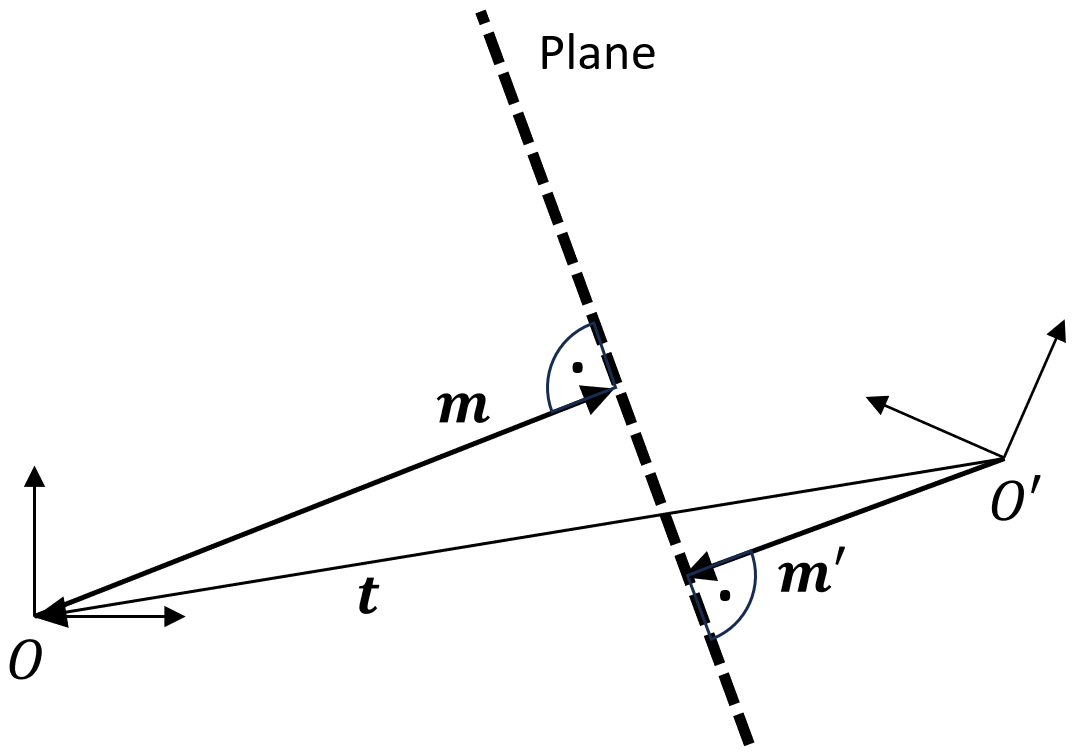
Figure 2Transformation of mirror vector from system O to system O′. If both systems had the same coordinate axes orientation, m and m′ would be parallel, and their position vector difference would lie in the mirror plane, i.e., .
Figure 3 shows a photograph of the experimental setup. Camera 1 is an AVT Manta G-145B 30 fps equipped with an Edmund Optics 59873 lens. The aperture is adjusted to . Camera 1 is focused on the SUT and observes the display via reflection on the SUT. Cameras 2 and 3 are AVT 1800 U-508m cameras with Computar M0528-MPW3 wide-angle lenses. Their aperture is adjusted to , and they are focused to infinity to record a sharp image over a large volume. The display is a LG 27UP850-W device, whose gamma curve has been linearized by prior calibration. The display can be conveniently moved by a robot manipulator.
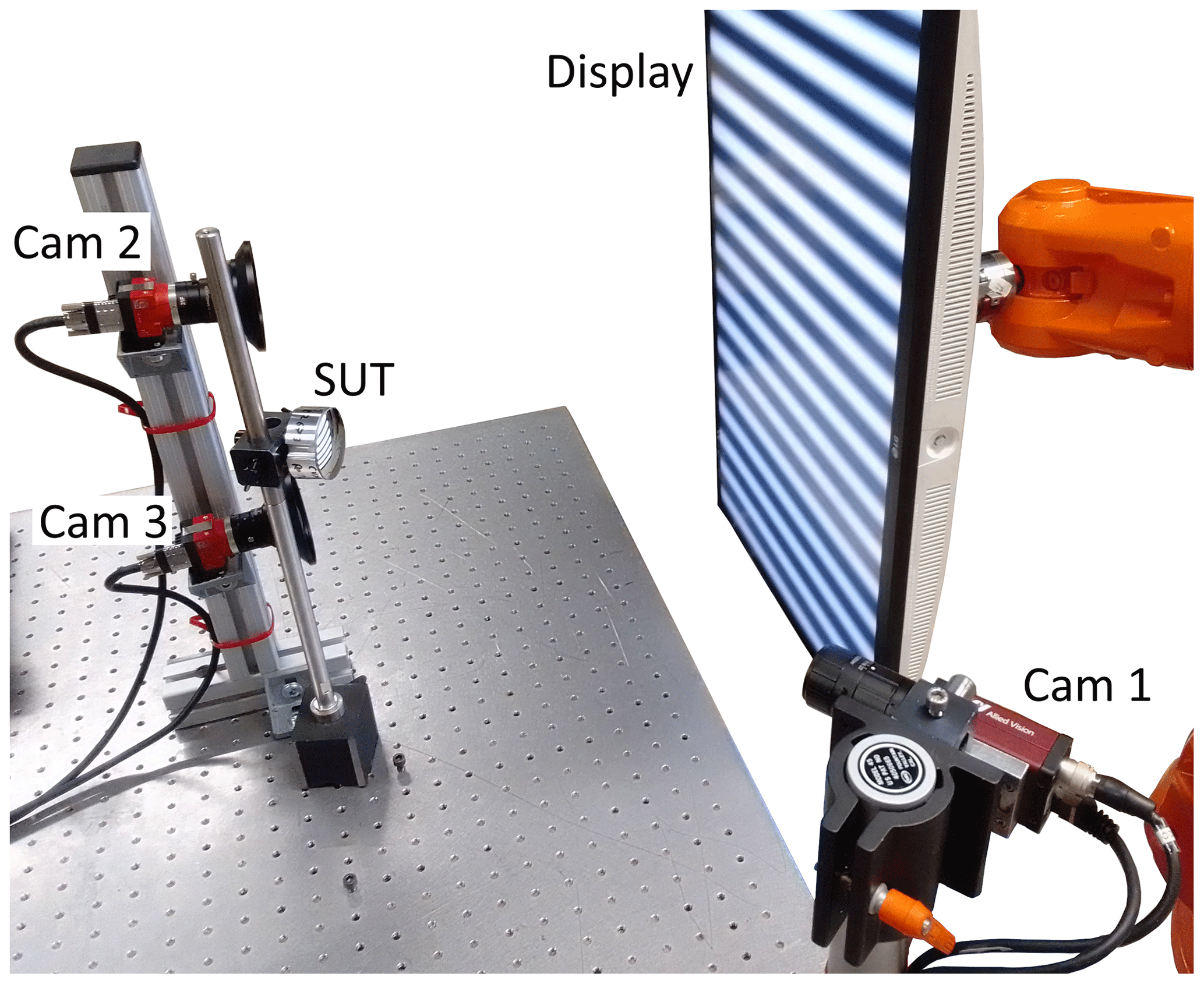
Figure 3Experimental setup. Camera 1 observes the display via reflection on the SUT. Cameras 2 and 3 observe the display directly.
As SUTs we use a planar mirror and two convex spherical mirrors with radii of curvature of approximately 200 and 100 mm. All samples have a diameter of 50 mm, of which the clear aperture of 45 mm diameter is used for evaluation. Each SUT is measured individually by placing it in the setup. To obtain data for shape reconstruction, the display is moved to five distances and each time a phase measurement is performed. For the 100 mm spherical mirror, multiple measurements are being recorded for each distance. This is necessary to cover the camera 1 field of view, which is enlarged by reflection on the high-curvature SUT.
Prior to SUT measurements, data for geometric calibration are gathered using the setup depicted in Fig. 4. Instead of the SUT, a at 633 nm planar calibration mirror is placed in the setup. The mirror is tilted to 17 different positions and each time a phase measurement is recorded. The rear of the mirror holder can be seen in Fig. 5. It features four nests, which are bearings with a cavity where the SMR locks magnetically. The nests are in the field of view of the laser tracker. The tracked 0.5 in. SMR can be placed successively in each of the nests to obtain coordinates that are rigidly connected to the mirror.
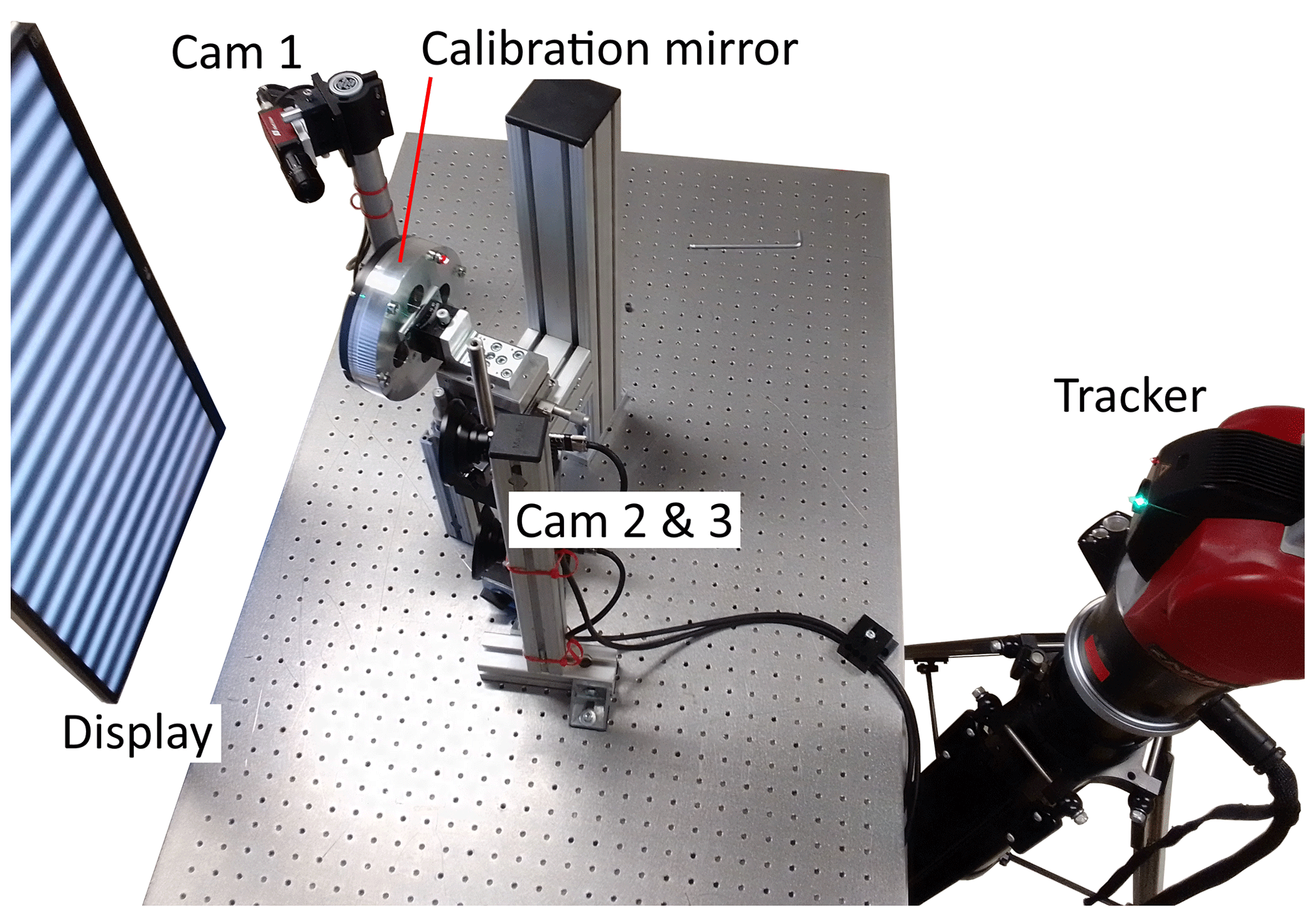
Figure 4Calibration setup. Camera 1 observes the display via reflection on a large planar calibration mirror. Cameras 2 and 3 observe the display directly. The tracker records the coordinates of the SMR which can be placed at four nests at the rear of the mirror holder.
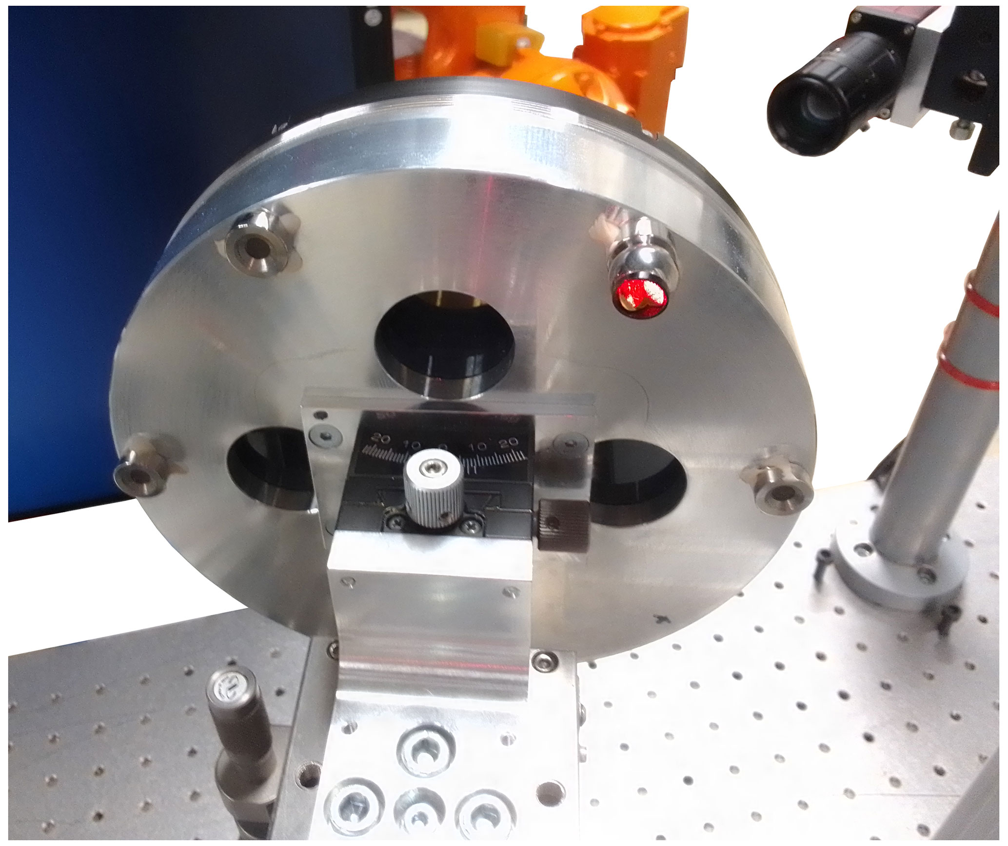
Figure 5Rear of the calibration mirror holder with four nests and the SMR attached to one of the nests.
4.1 Evaluation of tracker data
The determination of nest coordinates by the tracker might be affected by multiple error sources that do not originate from the tracker itself, such as thermal expansion of the calibration mirror hold or an imperfect snapping of the SMR to a nest due to dust or scratches. We repeat for each mirror position the measurement of the four nest coordinates four times to check repeatability. For all measurements and all nests, the deviation of coordinates of a nest from their mean is less than 5 µm. Using the Kabsch algorithm (Kabsch, 1976), we also aligned the averaged nest coordinates of different measurements to check for systematic changes of the nest's relative coordinates. This yields a maximum deviation of the nest coordinates of 4 µm, which shows sufficient consistency of the tracker data.
As described in Sect. 2.2, we fit planes to the four nest coordinates to obtain mirror vectors. As each of the four nests is measured four times, we can also estimate the mirror vector statistics by creating 44=256 samples of four nests and fit a plane to each sample. For example, the correlation (Draper and Smith, 1998, p. 143) of the first mirror vector is
This shows significant correlation between the components, which is reasonable since a slight change of only one of the components can severely increase the deviation of the plane from the nests. The other components then have to change as well to compensate and keep the plane deviation at the measured level. The correlation must be considered when we do a maximum likelihood estimation based on the mirror vectors.
The mirror vectors of the tracker are given in some coordinate frame OT. To compare them with the mirror vectors from the geometric calibration, we optimize the transformation from OC1 to OT such that the mirror vectors align as well as possible. As the components of each tracker mirror vector are correlated, we use generalized nonlinear least squares (Seber and Wild, 1989, pp. 27–28) and minimize so that each difference fj of mirror vectors is weighted by the inverse of the covariance matrix Cj of the tracker mirror vector of the jth measurement. To solve the optimization problem, we use the MATLAB function lsqnonlin (The MathWorks Inc., 2023b). After alignment, the angle between mirror vectors from the tracker and from geometric calibration is on average 21±3 and 30 arcsec at maximum. This shows the presence of systematic errors in the geometric calibration, as the difference of mirror angles is well above uncertainty.
4.2 Shape reconstruction
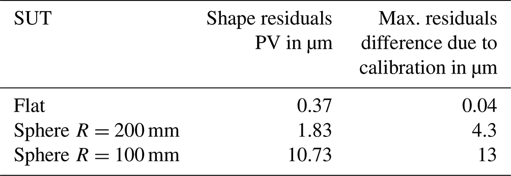
We use the geometric calibration result to reconstruct the shape of measured SUTs. A performance criterion for shape reconstruction is the deviation of the reconstructed shape from reference. The reference radii of the spherical mirrors were determined at Physikalisch Technische Bundesanstalt (PTB), Braunschweig, Germany, to be (99.993±0.001) and (200.069±0.001) mm. For our evaluation, the uncertainty of the reference radii is negligible. After fitting a plane or sphere with the respective reference radius to the SUT shape, we obtain fit residuals as depicted in Fig. 6. Peak-to-valley (PV) values for the residuals are shown in Table 1.
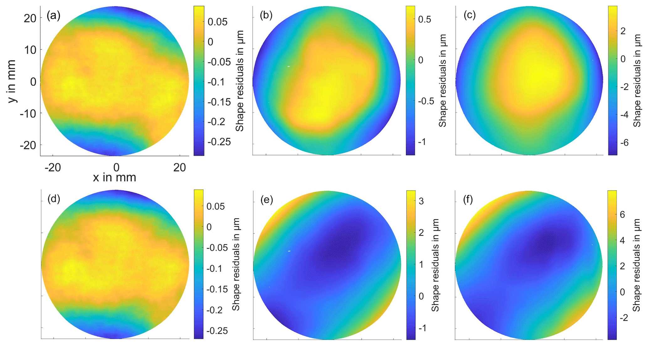
Figure 6Shape residuals. (a) Flat mirror, (b) convex mirror with radius 200 mm, and (c) convex mirror with radius 100 mm. (d, e, f) Corresponding shape residuals obtained with merged geometric calibration; see Sect. 4.3. The shape residuals increase with curvature and are of similar size for both calibrations. However, for nonzero curvature, their shape is different. It shows that the deviation from reference of the mirror positions in geometric calibration leads to considerable changes of reconstructed shape for SUTs with nonzero curvature.
Table 1Shape residuals' peak-to-valley (PV) results for multiple SUTs. Right column: maximum difference of the residuals to the residuals obtained with the merged geometric calibration. For an explanation of merged geometric calibration see Sect. 4.3.
The residuals of the flat mirror are small. It is therefore not suitable to expose calibration errors, or the general shape reconstruction accuracy, of the PMD–ADR method. Still, the good reconstruction of the flat mirror shape indicates consistency of the recorded phase data with the camera calibration. This means that camera 1 is probably calibrated well, and cameras 2 and 3 are probably calibrated well in the center of their field of view, where the phase values were recorded that go into shape reconstruction. For nonzero curvature, the deviations are larger. It is of interest if the geometric calibration error that caused the deviation of mirror vectors can cause such shape deviations.
4.3 “Merged” geometric calibration
To investigate whether the observed deviation of mirror vectors during geometric calibration can cause the observed shape deviations, we also perform a merged geometric calibration, where the mirror poses determined with the laser tracker are incorporated into the geometric calibration procedure. The optimization of the mirror vectors is thereby replaced by the optimization of TT,1 to have the mirror vectors available in OC1 coordinates. The merged geometric calibration result for T2&3,1 can then also be used for shape reconstruction.
Figure 6 shows the shape residuals of both calibrations for comparison. For every SUT, the residuals are different but of similar magnitude. The large shape deviations of merged geometric calibration are not unreasonable, despite the more accurate mirror vectors, because the underlying physical model of calibration did not change. For example, both calibration algorithms do not incorporate deviations of the calibration mirror from planarity, if that was the relevant source of error. Table 1 features the maximum differences of residuals of both calibrations. The flat mirror residuals are small and almost identical, which again shows that a flat mirror is not able to give insight into geometric calibration errors. The other differences are of similar size as the residuals themselves. Additionally, the increase in shape deviation with curvature is similar for both calibrations. The error source in geometric calibration that causes the mirror vectors to deviate from the reference may therefore very well cause the observed shape reconstruction deviations. This is a valuable result to us, since increased modeling effort can now be concentrated at the geometric calibration and prior calibration steps in order to improve measurement accuracy. Error sources that only affect the SUT measurement can for the moment be omitted, for example, the asymmetric point spread function that originates from the catadioptric system formed by the camera and the SUT (Zhang et al., 2021b). However, the above result does not exclude error sources that enter during SUT measurement and influence the shape reconstruction in the same order of magnitude.
Multiple sources of error are possible. Refraction at the display cover glass can cause deviations of the measured phase (Reh et al., 2014; Petz et al., 2020). We incorporated a cover glass correction algorithm and verified it using simulation, but for reasonably guessed cover glass parameters we were not able to reduce the deviation of mirror vectors or the shape deviations. We also excluded an imprecisely known display pixel pitch as error source, by comparing phase measurements obtained from the PMD–ADR display with phase measurements obtained from a display with precisely known pixel pitch, both recorded with the same cameras. Improving PMD–ADR accuracy will therefore be an ongoing topic in the future.
We have presented phase-measuring deflectometry (PMD) with active display registration (ADR), which is a shape measurement technique for specular surfaces. Geometric calibration is an important step for PMD–ADR. As one result of geometric calibration, one obtains the positions of the calibration mirror. We implemented a laser-tracker-based method to perform a reference measurement of the calibration mirror positions. The reference method yields different mirror positions than the geometric calibration. This shows systematic errors in the geometric calibration. By employing a merged geometric calibration, we were able to show that these errors are sufficient to yield shape reconstruction deviations of similar size as the observed deviations. This result helps us to guide our future efforts to improve modeling towards the calibration stage of PMD–ADR.
Code and data underlying the results presented may be obtained from the authors upon reasonable request.
YS performed the investigation and prepared the manuscript. RBB conceptualized and administered the project, acquired the funding, and supervised this work. YS and RBB reviewed and edited the manuscript.
The contact author has declared that neither of the authors has any competing interests.
Publisher's note: Copernicus Publications remains neutral with regard to jurisdictional claims made in the text, published maps, institutional affiliations, or any other geographical representation in this paper. While Copernicus Publications makes every effort to include appropriate place names, the final responsibility lies with the authors.
This article is part of the special issue “Sensors and Measurement Science International SMSI 2023”. It is a result of the 2023 Sensor and Measurement Science International (SMSI) Conference, Nuremberg, Germany, 8–11 May 2023.
The authors gratefully acknowledge the radius measurement of the spherical mirrors at Physikalische Technische Bundesanstalt (PTB).
This research has been supported by the Deutsche Forschungsgemeinschaft (grant no. 444018140).
This paper was edited by Andreas Schütze and reviewed by two anonymous referees.
Bartsch, J. and Bergmann, R. B.: Phasenmessende Deflektometrie mit aktiver Displayregistrierung, in: Proc. of 121th DGaO conference, ISSN: 1614-8436, urn:nbn:de:0287-2020-A012-2, https://www.dgao-proceedings.de/download/121/121_a12.pdf (last access: 27 September 2023), 2020. a
Bartsch, J., Kalms, M., and Bergmann, R. B.: Improving the calibration of phase measuring deflectometry by a polynomial representation of the display shape, J. Eur. Opt. Soc.-Rapid, 49, 20, https://doi.org/10.1186/s41476-019-0116-1, 2019. a
Bartsch, J., Sperling, Y., and Bergmann, R. B.: Efficient vision ray calibration of multi-camera systems, Opt. Express, 29, 17125–17139, https://doi.org/10.1364/OE.424337, 2021. a
Bothe, T., Li, W., Schulte, M., von Kopylow, C., Bergmann, R. B., and Jüptner, W. P. O.: Vision ray calibration for the quantitative geometric description of general imaging and projection optics in metrology, Appl. Optics, 49, 5851–5860, https://doi.org/10.1364/AO.49.005851, 2010. a
Burge, J. H., Su, P., Zhao, C., and Zobrist, T.: Use of a commercial laser tracker for optical alignment, in: Optical System Alignment and Tolerancing, edited by: Sasian, J. M. and Ruda, M. C., International Society for Optics and Photonics, SPIE, 6676, p. 66760E, https://doi.org/10.1117/12.736705, 2007. a
Draper, N. R. and Smith, H.: Applied Regression Analysis, Wiley Series in Probability and Statistics, 3rd edn., John Wiley & Sons, Inc., Hoboken, NJ, https://doi.org/10.1002/9781118625590, ISBN 9781118625590, 1998. a
Gallagher, B. B.: Optical Shop Applications for Laser Tracker, PhD thesis, University of Arizona, Tucson, AZ, 2003. a
Hesch, J. A., Mourikis, A. I., and Roumeliotis, S. I.: Determining the camera to robot-body transformation from planar mirror reflections, in: 2008 IEEE Int. C. Int. Robot., Nice, France, 22–26 September 2008, IEEE, 3865–3871, https://doi.org/10.1109/IROS.2008.4651121, 2008. a, b
Höfer, S., Burke, J., and Heizmann, M.: Infrared deflectometry for the inspection of diffusely specular surfaces, Advanced Optical Technologies, 5, 377–387, https://doi.org/10.1515/aot-2016-0051, 2016. a
Huang, L., Xue, J., Gao, B., Zuo, C., and Idir, M.: Zonal wavefront reconstruction in quadrilateral geometry for phase measuring deflectometry, Appl. Optics, 56, 5139–5144, https://doi.org/10.1364/AO.56.005139, 2017. a
Huang, L., Idir, M., Zuo, C., and Asundi, A.: Review of phase measuring deflectometry, Opt. Laser Eng., 107, 247–257, https://doi.org/10.1016/j.optlaseng.2018.03.026, 2018. a, b
Huang, R., Su, P., and Burge, J. H.: Deflectometry measurement of Daniel K. Inouye Solar Telescope primary mirror, in: Optical Manufacturing and Testing XI, edited by: Fähnle, O. W., Williamson, R., and Kim, D. W., International Society for Optics and Photonics, SPIE, 9575, p. 957515, https://doi.org/10.1117/12.2189258, 2015a. a, b
Huang, R., Su, P., Burge, J. H., Huang, L., and Idir, M.: High-accuracy aspheric x-ray mirror metrology using Software Configurable Optical Test System/deflectometry, Opt. Eng., 54, 084103, https://doi.org/10.1117/1.OE.54.8.084103, 2015b. a, b
Kabsch, W.: A solution for the best rotation to relate two sets of vectors, Acta Crystallogr. A, 32, 922–923, https://doi.org/10.1107/S0567739476001873, 1976. a
Knauer, M. C., Kaminski, J., and Häusler, G.: Phase measuring deflectometry: a new approach to measure specular free-form surfaces, in: Optical Metrology in Production Engineering, edited by: Osten, W. and Takeda, M., International Society for Optics and Photonics, SPIE, 5457, 366–376, https://doi.org/10.1117/12.545704, 2004. a, b
Li, W., Sandner, M., Gesierich, A., and Burke, J.: Absolute optical surface measurement with deflectometry, in: Interferometry XVI: Applications, edited by: Furlong, C., Gorecki, C., and Novak, E. L., International Society for Optics and Photonics, SPIE, 8494, p. 84940G, https://doi.org/10.1117/12.928690, 2012. a
Li, W., Huke, P., Burke, J., von Kopylow, C., and Bergmann, R. B.: Measuring deformations with deflectometry, in: Interferometry XVII: Techniques and Analysis, edited by Creath, K., Burke, J., and Schmit, J., International Society for Optics and Photonics, SPIE, 9203, p. 92030F, https://doi.org/10.1117/12.2063446, 2014. a
Liu, Y., Huang, S., Zhang, Z., Gao, N., Gao, F., and Jiang, X.: Full-field 3D shape measurement of discontinuous specular objects by direct phase measuring deflectometry, Sci. Rep.-UK, 7, 10293, https://doi.org/10.1038/s41598-017-11014-5, 2017. a
Muralikrishnan, B., Phillips, S., and Sawyer, D.: Laser trackers for large-scale dimensional metrology: A review, Precis. Eng., 44, 13–28, https://doi.org/10.1016/j.precisioneng.2015.12.001, 2016. a
Petz, M.: Rasterreflexions-Photogrammetrie, vol. 1, in: Schriftenreihe des Instituts für Produktionsmesstechnik, Shaker Verlag, Aachen, ISBN 9783832249441, 2006. a
Petz, M., Dierke, H., and Tutsch, R.: Advances in deflectometric form measurement, in: Forum Bildverarbeitung 2020, edited by: Heizmann, M. and Längle, T., KIT Scientific Publishing, Karlsruhe, 157–169, https://doi.org/10.5445/KSP/1000124383, ISBN 978-3-7315-1053-6, 2020. a, b, c
Reh, T., Li, W., Burke, J., and Bergmann, R.: Improving the Generic Camera Calibration technique by an extended model of calibration display, J. Eur. Opt. Soc.-Rapid, 9, 14044, https://doi.org/10.2971/jeos.2014.14044, 2014. a
Seber, G. A. F. and Wild, C. J.: Nonlinear Regression, in: Wiley Series in Probability and Statistics, John Wiley & Sons, Inc., Hoboken, NJ, https://doi.org/10.1002/0471725315, ISBN 9780471725312, 1989. a
Sperling, Y. and Bergmann, R.: Active Display Registration in Phase Measuring Deflectometry, in: Proceedings Sensor and Measurement Science International 2023 Conference, Nuremberg, 8–11 May 2023, AMA Service GmbH, Wunstorf, 49–50, https://doi.org/10.5162/SMSI2021/A3.3, 2023. a
Su, P., Parks, R. E., Wang, L., Angel, R. P., and Burge, J. H.: Software configurable optical test system: a computerized reverse Hartmann test, Appl. Optics, 49, 4404–4412, https://doi.org/10.1364/AO.49.004404, 2010. a
Takahashi, K., Nobuhara, S., and Matsuyama, T.: A new mirror-based extrinsic camera calibration using an orthogonality constraint, in: 2012 Proc. CVPR, Providence, RI, USA, 16–21 June 2012, IEEE, 1051–1058, https://doi.org/10.1109/CVPR.2012.6247783, 2012. a
The MathWorks Inc.: fminunc, https://uk.mathworks.com/help/optim/ug/fminunc.html, last access: 4 September 2023a. a
The MathWorks Inc.: lsqnonlin, https://uk.mathworks.com/help/optim/ug/lsqnonlin.html, last access: 4 September 2023b. a
Wang, Y., Xu, Y., Zhang, Z., Gao, F., and Jiang, X.: 3D Measurement of Structured Specular Surfaces Using Stereo Direct Phase Measurement Deflectometry, Machines, 9, 170, https://doi.org/10.3390/machines9080170, 2021. a
Werling, S., Mai, M., Heizmann, M., and Beyerer, J.: Inspection of Specular and Partially Specular Surfaces, Metrol. Meas. Syst., 16, 415–431, 2009. a
Xu, X., Zhang, X., Niu, Z., Wang, W., and Xu, M.: Extra-detection-free monoscopic deflectometry for the in situ measurement of freeform specular surfaces, Opt. Lett., 44, 4271–4274, https://doi.org/10.1364/OL.44.004271, 2019. a
Xu, Y., Gao, F., Zhang, Z., and Jiang, X.: A calibration method for non-overlapping cameras based on mirrored absolute phase target, Int. J. Adv. Manuf. Tech., 104, 9–15, https://doi.org/10.1007/s00170-018-1704-8, 2019. a
Yue, H.-M., Wu, Y.-X., Song, Y.-P., and Liu, Y.: Solution to the slope-height ambiguity problem in phase measuring deflectometry based on a co-axial telecentric optical path, Meas. Sci. Technol., 31, 045007, https://doi.org/10.1088/1361-6501/ab472f, 2020. a
Zhang, X., Li, D., and Wang, R.: Active speckle deflectometry based on 3D digital image correlation, Opt. Express, 29, 28427–28440, https://doi.org/10.1364/OE.437531, 2021a. a
Zhang, X., Niu, Z., Ye, J., and Xu, M.: Correction of aberration-induced phase errors in phase measuring deflectometry, Opt. Lett., 46, 2047–2050, https://doi.org/10.1364/OL.415953, 2021b. a
Zhang, Z., Chang, C., Liu, X., Li, Z., Shi, Y., Gao, N., and Meng, Z.: Phase measuring deflectometry for obtaining 3D shape of specular surface: a review of the state-of-the-art, Opt. Eng., 60, 020903, https://doi.org/10.1117/1.OE.60.2.020903, 2021c. a