the Creative Commons Attribution 4.0 License.
the Creative Commons Attribution 4.0 License.
 | 18 Nov 2025
Conceptual design of additive manufactured capacitive displacement sensors for adaptive pin array grippers
Steffen Schröder
Thomas M. Wendt
Stefan J. Rupitsch
This research presents a capacitive displacement sensor concept, designed for integration into a pin array gripper. The sensor employs a plate capacitor structure to measure the displacement of individual pins, with each pin positioned to move between the electrodes. The sensor is designed with sensing, guiding and shielding electrodes to maintain a homogeneous electric field between the capacitor plates and a linear capacitance response. We implemented a shielding strategy with the objective of minimising external interference and reducing mutual interference between individual displacement sensors. This ensures stable operation and reliable measurements, which are crucial for the reliable functioning in dynamic environments. The design is optimised for additive manufacturing, offering advantages in customisation, adaptability to various pin gripping systems and a compact form factor. It also opens up new possibilities for integrating sensing elements directly into the structure of the gripper. A prototype sensor was fabricated using additive manufacturing and tested in an experimental setup to validate its functionality and to enable a comparison of its performance against the results of numerical simulations.
- Article
(7098 KB) - Full-text XML
- BibTeX
- EndNote


In the rapidly evolving field of robotics and automation, the demand for gripping systems has increased significantly (Ivanov et al., 2024). A variety of gripping systems are available, including parallel jaw grippers, vacuum grippers, human hand grippers and pin array grippers (Hernandez et al., 2023; Khadkotkar and Mishra, 2024). The focus is on optimising the contour and kinematics of the gripper to adapt to the surface and geometry of the workpiece being gripped. Unlike standard shapes such as cuboids and spheres, the handling of 3-D free-form objects presents unique challenges due to their irregular contours, requiring the use of complex gripping systems for effective manipulation. Adaptive gripping systems adjust to the characteristics of the object to be gripped and can grip objects with different shapes, sizes and weights (Hernandez et al., 2023). These systems are based on structural compliance, either through joints (e.g. flexure joints) or through compliant finger pads on the contact surfaces (Chang et al., 2019a). Foams, silicones and other soft materials are used. The flexibility increases the stability of the grip and reduces the force required to grasp the object. It can also increase the contact friction between the gripper jaws and the object (Chang et al., 2019a; Goh et al., 2022a).
Pin array gripping systems consist of several individual pins that can move independently of each other and adapt to various structures (Mo et al., 2018; Mo and Zhang, 2019; Flintoff et al., 2018). Unlike conventional compliant structures, pins are compliant in one direction and can withstand shear forces (Chang et al., 2019b). This distinguishes them from typical compliant structures that deform evenly in all directions, such as foams, silicones and other soft materials.
Additive manufacturing enables new gripping concepts, especially for the direct integration of sensors (Khosravani and Reinicke, 2020; Goh et al., 2022b; Hangst et al., 2022). Sensory data on the gripped object and the gripping process allow a detailed understanding of the interaction between the gripping mechanism and the object (Goh et al., 2022b). This acquisition opens up new analysis possibilities such as precise object recognition, slippage detection (slipping of the object during the gripping process) and the detection of anomalies in the gripping process. Potential sources of error can be identified at an early stage, and appropriate action can be taken by continuously monitoring the gripping process. The contribution of this research is the development of a capacitive displacement sensor optimised to be additive manufactured. This offers advantages in terms of customisation, adaptability to different pin gripper designs and a compact form factor. It opens up new possibilities for integrating sensing elements directly into the structure of the gripper, enabling fully printed pin grippers. The design freedom of additive manufacturing makes it possible to optimise the functionality and performance of gripping systems while reducing complexity (Xin et al., 2024; Hassan et al., 2023; Hossain et al., 2025). In addition, the manufacturing process is simplified by the single process approach (Iftekar et al., 2023). This addresses the varying demands, where the gripper's and sensor's requirement profiles are highly dependent on the specific object and task.
This sensor concept enables the measurement of the displacement of individual pins within the gripper. The exploited sensor concept is based on a grounded parallel plate capacitor. A parallel plate capacitor is created by applying different electric potentials to two electrodes, generating an electric field between them. Without taking into account stray fields, the capacitance C of a plate capacitor can be calculated by
In Eq. (1), ε0 represents the permittivity of the vacuum space, εr is the relative permittivity of the dielectric material between the electrodes, d is the distance between the electrodes and A is the area of the sensing plate. Consequently, the capacitance of a parallel plate capacitor is affected by the geometry of the electrodes, the distance between the plates and the dielectric properties of the material. The change in dielectric properties is the basic working principle of the presented sensor design. The space between the plates consists of two different materials and can be thought of as two capacitors being electrically connected in parallel. The current location of the pin divides the two capacitors horizontally into one containing air (relative permittivity εAir) and the other containing the pin material (relative permittivity εPin). In addition, an air gap dGap must be regarded as capacitors connected in series. This provides the necessary mechanical freedom for the pin to move within the sensor. Moving the pin causes the total capacitance to change due to the changing partition of air and pin material. The areas of these regions are determined by the pin's position x, relative to the total length of the measurement range, where a higher x means that the pin is pulled farther out of the sensor. According to this, the total capacitance related to the pin position Ctotal(x) can be simplified as a linear equation and calculated by
In Eq. (2), b represents the width of the electrode and C0 represents the capacitance of the sensor with a fully inserted pin. This equation forms the basis for the analytic approach determining the pin's position from the measured capacitance.
COMSOL Multiphysics was used for the finite element method (FEM). The numerical simulations were performed with polylactic acid (PLA), acrylonitrile butadiene styrene (ABS-T) and acrylonitrile styrene acrylate (ASA) as pin material. The assumed εr is 2.8 for PLA, 2.65 for ABS-T and 3.22 for ASA. The assumed values seem realistic, compared with the results of other studies for PLA (Kuzmanić et al., 2023; Dichtl et al., 2017), ABS-T and ASA (Kalaš et al., 2021). These studies provide reference points but do not cover the desired measuring frequency. In the context of the proof of concept, the assumptions appear to be a sufficient starting point.
The concept builds on previous work, in which a capacitive level sensor was designed (Hangst et al., 2022). The sensor includes sensing, guiding and shielding electrodes. The shielding electrode located on the opposite side of a sensing electrode forms the parallel plate capacitor with it. The guiding electrodes have the same voltage potential as the sensor sensing electrode. The sensor electrode concept for a pin gripper is shown in Fig. 1. It can be scaled by adding more electrodes according to the scheme as shown in Fig. 2 for three pins.
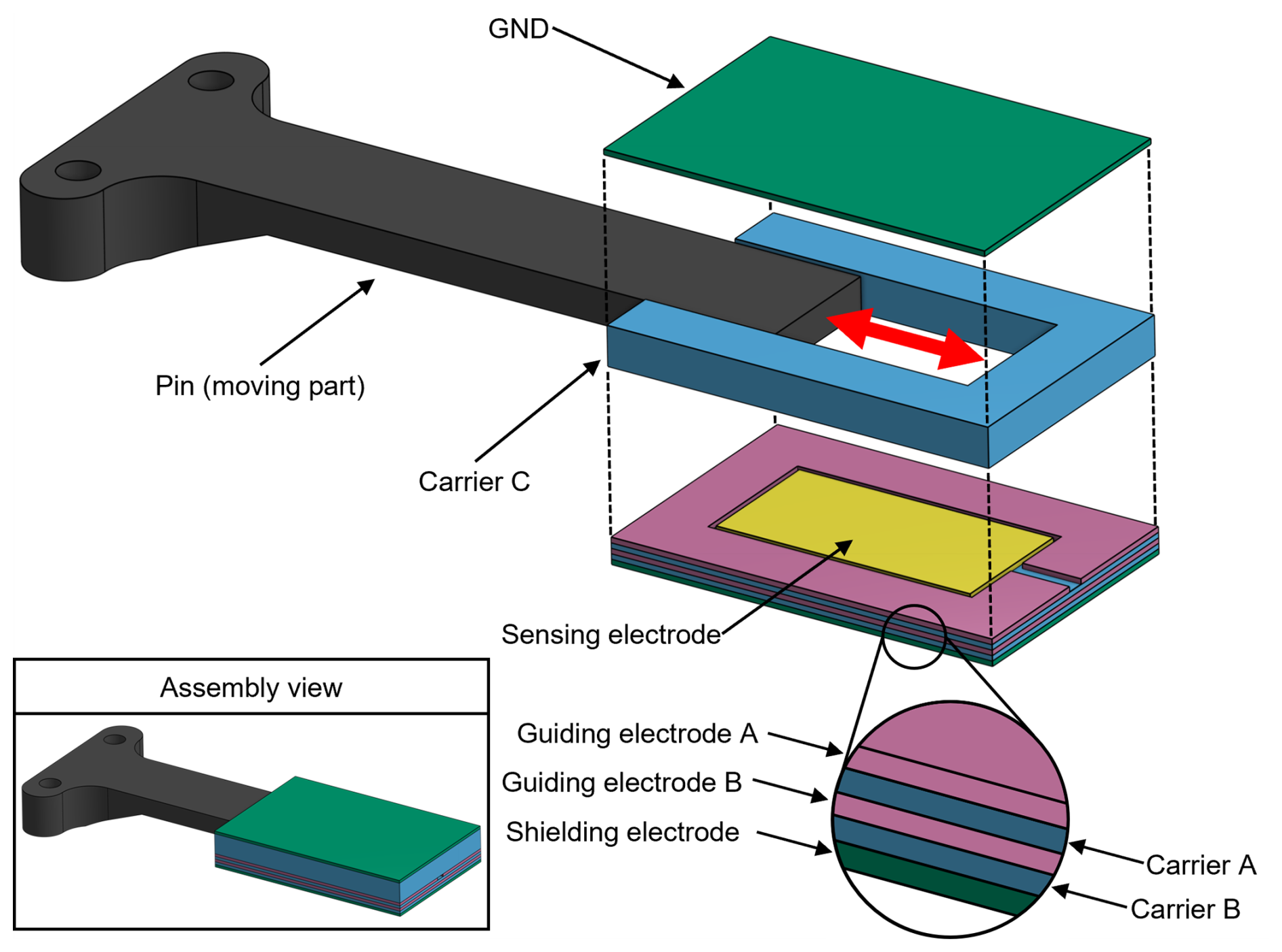
Figure 1Design of the sensor as a partial explosion view and as an assembly view with the pin partially inserted.
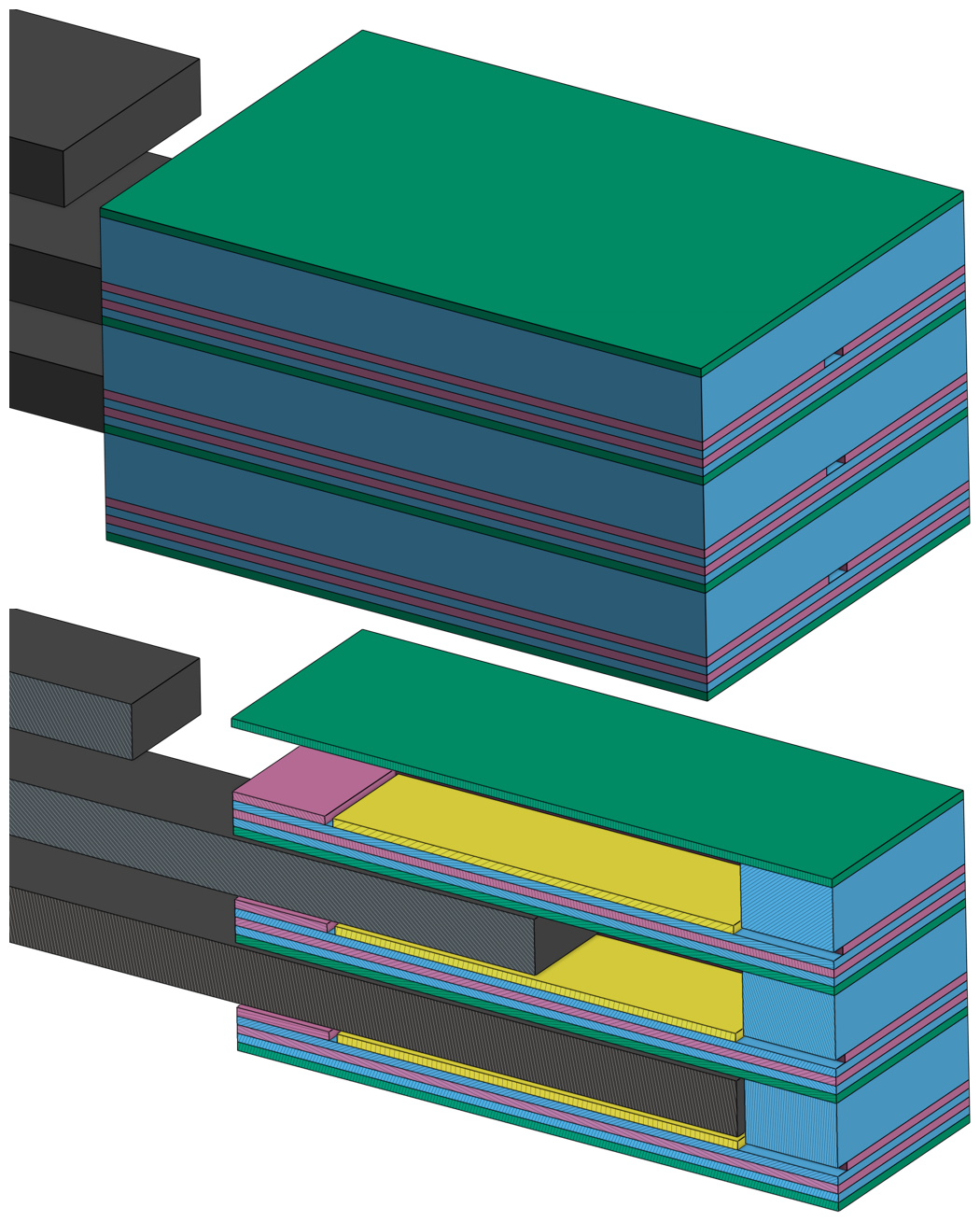
Figure 2Scaled sensor concept for a three-pin gripper as an overall view (top) and sectional view (bottom) with different pin positions.
The effect of the guiding electrode arrangement is shown in Fig. 3. Compared to the sensor without connected guiding electrodes, the electric field of the sensing electrode is directed within the measuring range, and the influence of the edge effects is minimised by the arrangement of the guiding electrode around the sensing electrode, leaving only the side to the measuring range open. The electric field in the measurement area is more homogeneous. The grounded shielding electrodes serve to safeguard the sensor from external influences, also preventing mutual interference between the individual pin sensors. The design provides linearity, precision and accuracy.
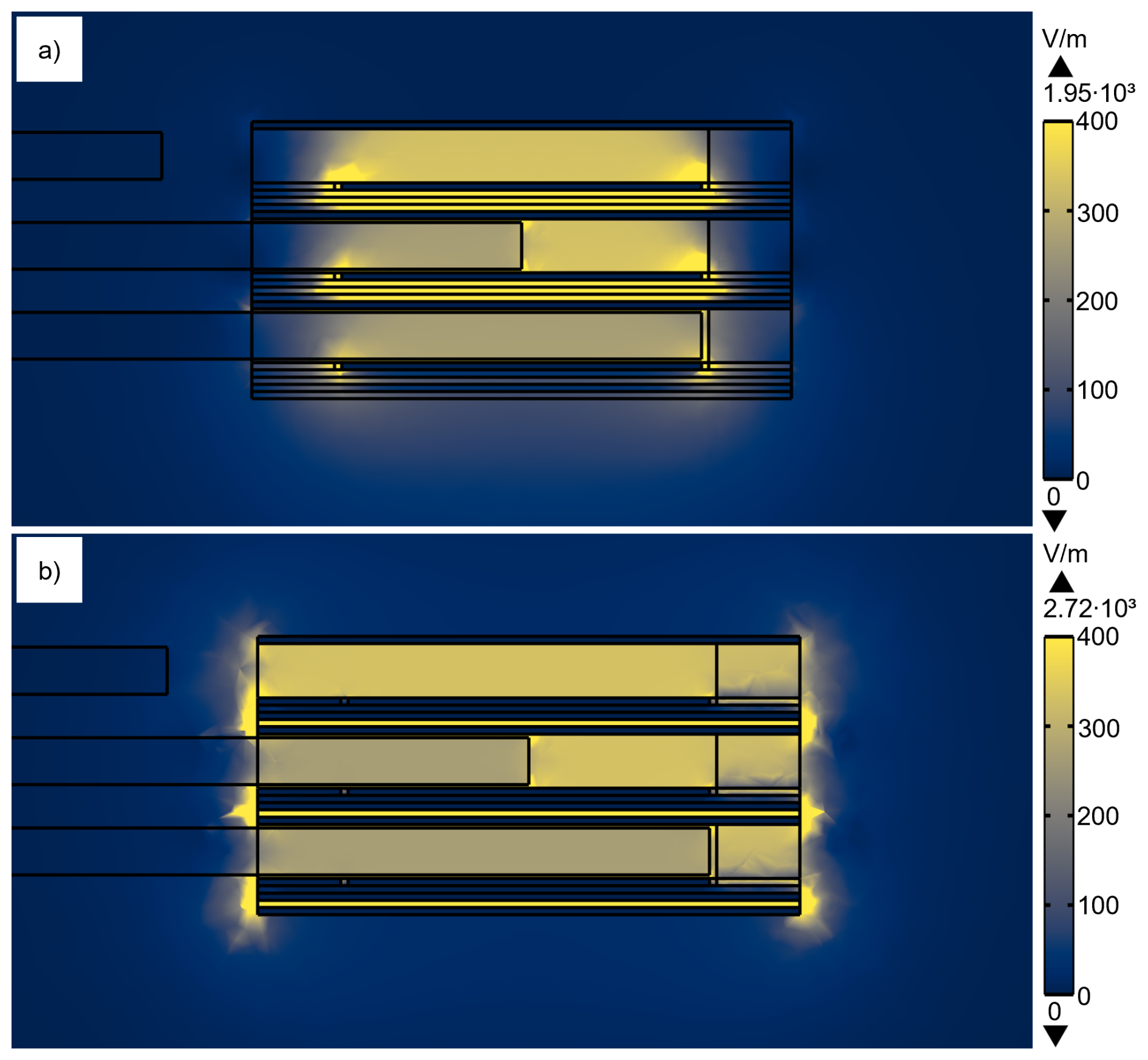
Figure 3Simulation of the electric field for the three-pin gripper with different pin positions, with a voltage of 1 V applied to the sensing electrodes (a) and with a voltage of 1 V applied to the sensing and guide electrodes (b).
A test sensor for one pin was designed for the purpose of establishing the concept's viability. The measuring range is 20 mm with a desired resolution of 1 mm. The geometric dimensions of the sensor are 20 mm in width, 30 mm in length and 5.4 mm in thickness. Each of the electrodes has a thickness of 0.4 mm. The sensor was manufactured using the 3-D printing system Neotech AMT 15X SA with a layer height of 0.2 mm and 100 % filling density. The 3-D printed sensor is made of PLA (ecoPLA, 3DJAKE) and conductive PLA from Protopasta. The conductive layers serve as electrodes. Copper wires are applied to integrate the electrodes into the evaluation circuit. The test sensor as complete and partially with the sensing side is shown in Fig. 4. The pins used for the measurements are made of PLA (ecoPLA, 3DJAKE), ABS-T (Filament PM) and ASA (Prusament ASA, Prusa Polymers) and were manufactured using a Prusa MK4S with a layer height of 0.2 mm and 100 % filling density. The dimensions of the pin are 10.4 mm in width and 2.6 mm in thickness. This results in a circumferential gap between the pin and the sensor of 0.2 mm. This provides the necessary mechanical freedom for the pin to move within the sensor, without a significant loss of capacitance change.
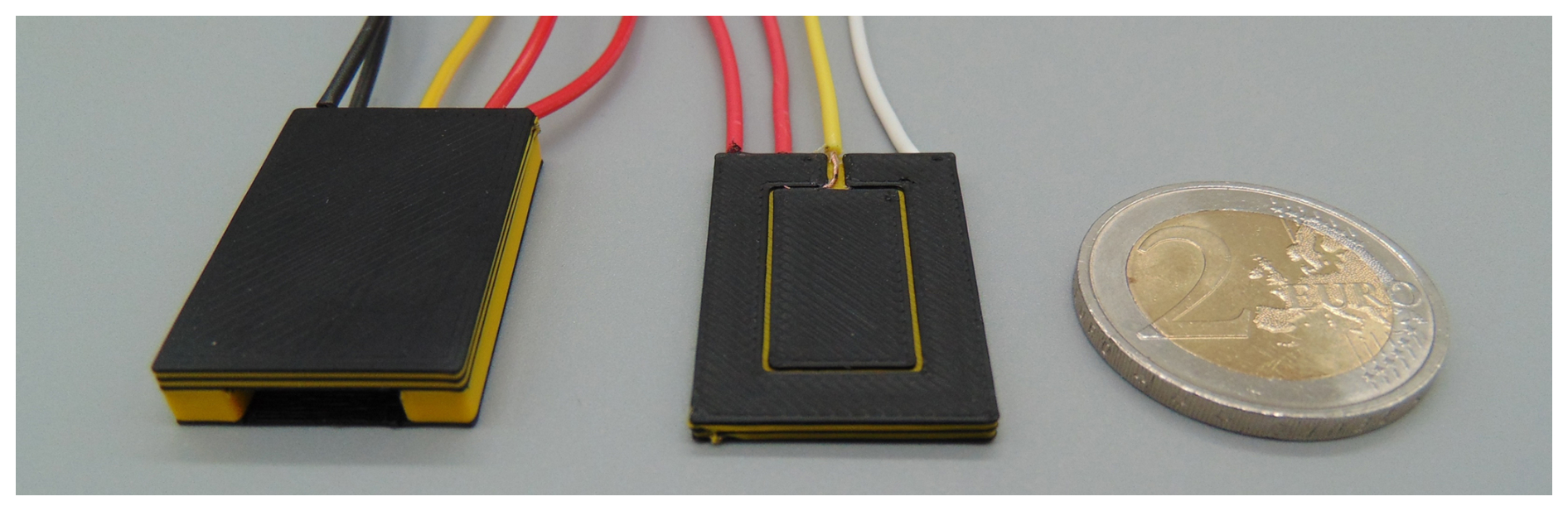
Figure 4Additively manufactured test sensor as complete (left) with the electrical connection cables for the guiding (red), sensing (yellow) and grounded electrodes (black) and partially with only the sensing side (right).
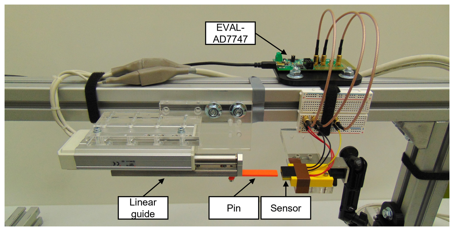
We tested the sensor in an experimental setup to verify the simulation results. The sensors were connected to a capacitance-to-digital converter (CDC), with measurements conducted using the EVAL-AD7747 board from the company Analog Devices. This board leverages the AD7747 CDC to achieve a resolution down to 20 aF and excellent linearity (±0.01 %) in capacitance measurements. The CDC is equipped with a port for active shielding, which is connected to the guiding electrodes (Devices, 2007). The excitation frequency used for the measurements is 16 kHz. A resistance in series with the measured capacitance affects the performance of the AD7747 CDC. This series resistance must be less than 10 kΩ to achieve the specified performance (Devices, 2007). A total of 1000 resistance measurements were conducted, with a Keithley 2450 SourceMeter. The measured average serial resistance of the sensing electrode is 851 Ω, with a standard deviation of 0.2 Ω. The evaluation board was connected to a PC where the data were collected and analysed in MATLAB. The measurements were carried out using two pins made of PLA, ABS-T and ASA, as shown in Fig. 5. The pin displacement is achieved with a linear guide (SMC LESH8RK-75B-R36P3), which moves the pin from 0 mm (pin is fully inserted) to 30 mm displacement (pin is 5 mm away from the sensor opening). The measurements were carried out in two different ways. First, the linear guide moves in 1 mm steps, and 100 measurements are taken for the capacitance for each step, with a sampling frequency of 8.1 Hz. Second, the linear guide moves back and forth with a constant speed of 10 mm s−1, and 1200 measurements are taken over time, with a sampling frequency of 45.5 Hz. Figure 6 shows the measurement setup.
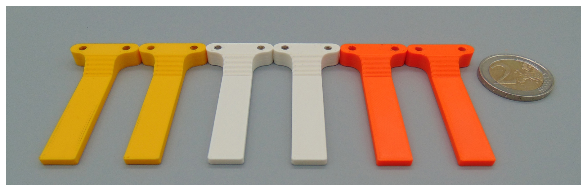
Figure 5PLA pins (yellow), ABS-T pins (white) and ASA pins (orange) used for the measurements.
We conducted experiments to compare the analytic and simulated capacitance with the measurement of the fabricated sensor. The operating range of the sensing electrode starts at 0 mm and extends to 20 mm due to the sensor design. The parasitic capacitance of the connecting wires, which were excluded from the analytic calculation and numerical simulation, was added to the values through mathematical addition. These values are based on the measurements of the sensor without a pin inside. The standard deviation of the measured values for the PLA pins ranges from 3 to 7 fF, while for the ABS-T pins, it ranges from 4 to 7 fF. For the ASA pins, the standard deviation ranges from 3 to 7 fF.
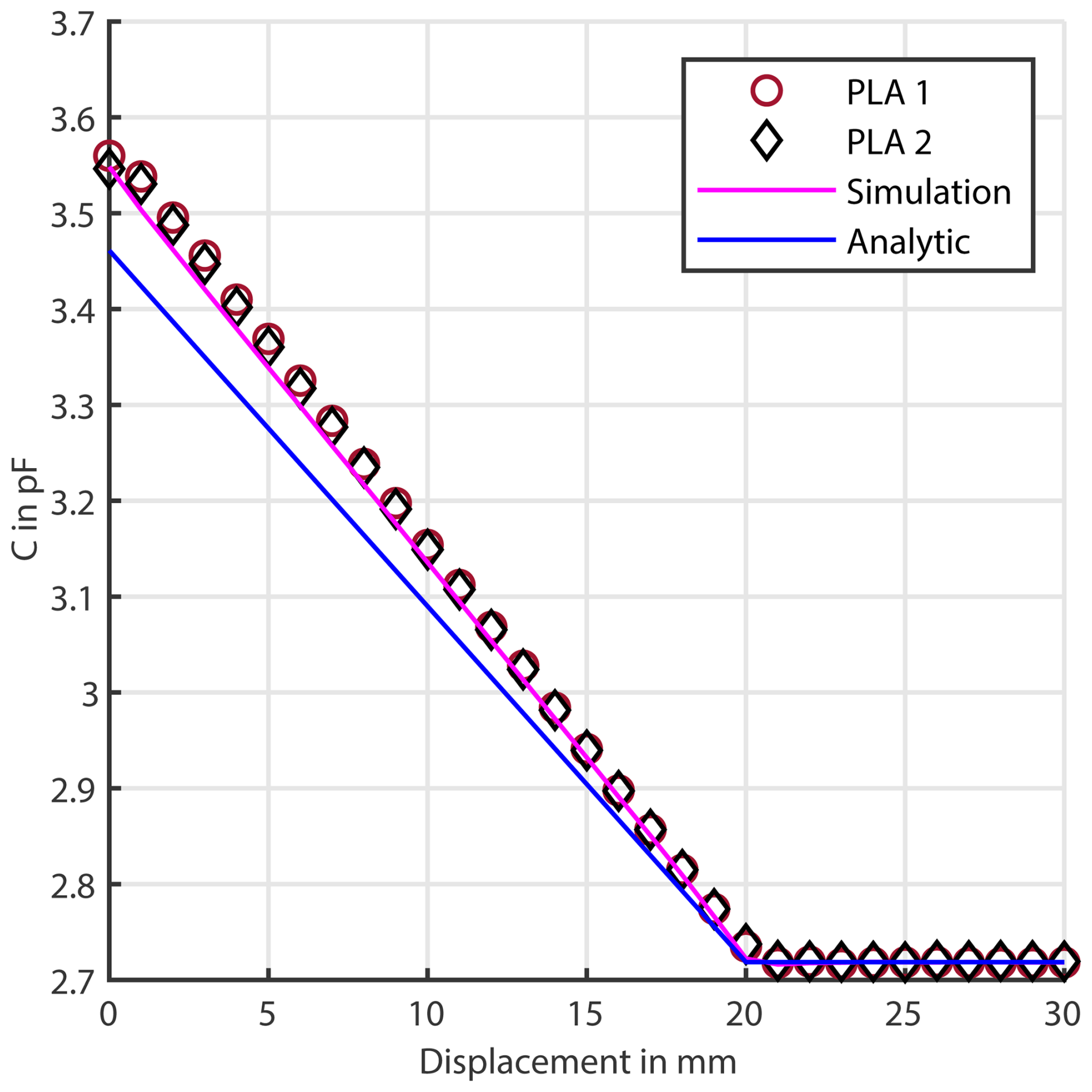
Figure 7Analytical, simulated and measured capacitance of the sensor for different displacements with different PLA pins.
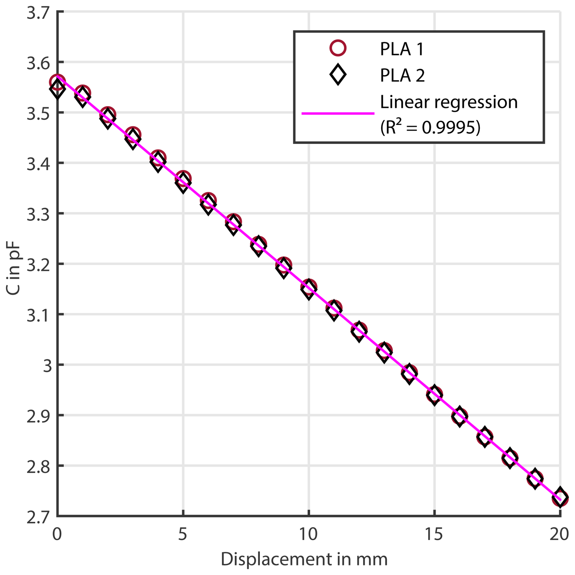
Figure 8Linear regression line for the measured capacitance of the sensor for different displacements with PLA pins.
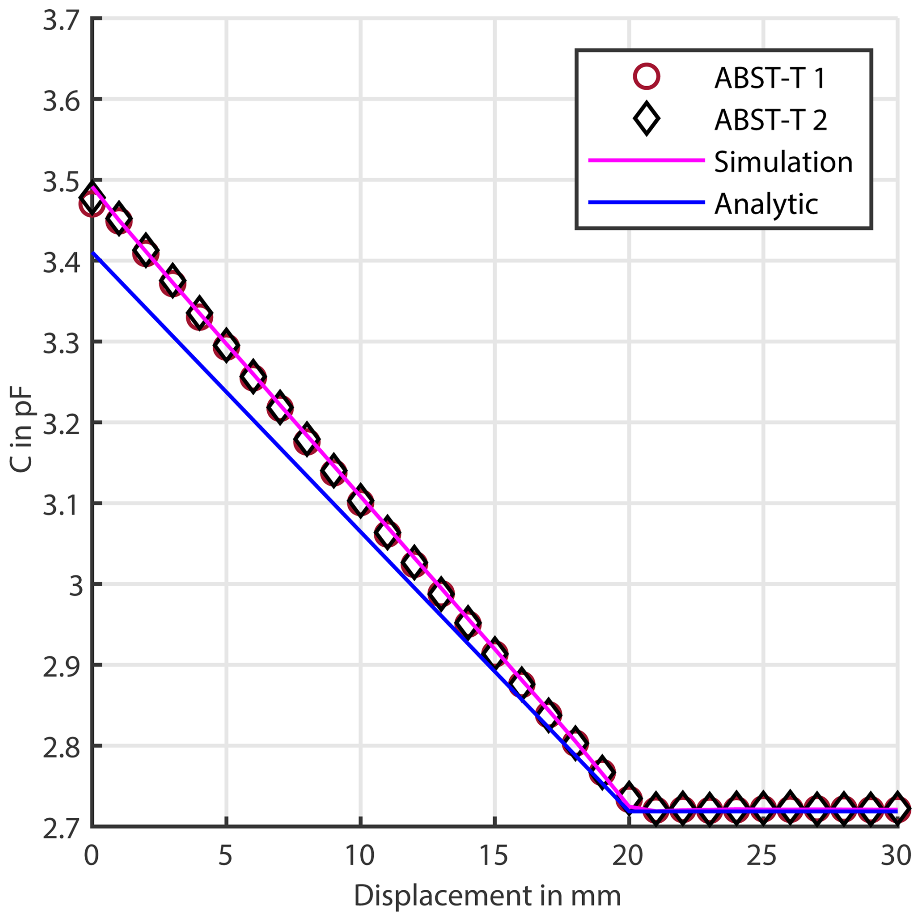
Figure 9Analytical, simulated and measured capacitance of the sensor for different displacements with different ABS-T pins.
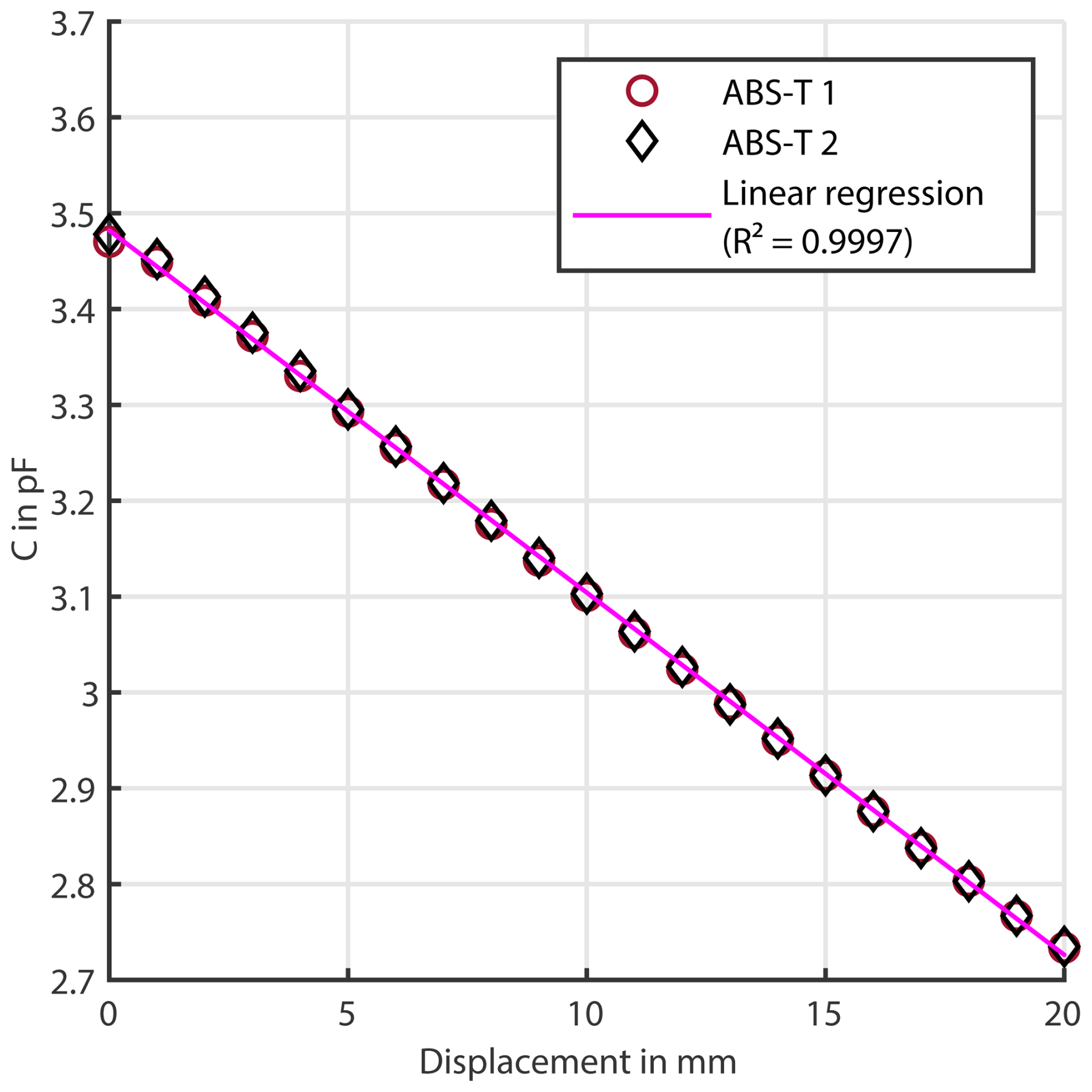
Figure 10Linear regression line for the measured capacitance of the sensor for different displacements with ABS-T pins.
Figure 7 shows the capacitance related to the pin position for the PLA pins. Both samples for PLA show a decrease in capacitance as displacement increases from 0 to 20 mm. Beyond 20 mm of displacement, the capacitance levels off at around 2.72 pF. A linear regression analysis was conducted using the measurements from both samples in the operating range to demonstrate the linearity of the relationship between displacement and capacitance, as shown in Fig. 8. The results indicate the linear behaviour of the sensor for the PLA samples in the operating range of the sensing electrode, as supported by the R2 value of 0.9995. Figure 9 shows the capacitance related to the pin position for the ABS-T pins and Fig. 11 for the ASA pins. Both samples for ABS-T and ASA show a linear decrease in capacitance as displacement increases from 0 to 20 mm. Beyond 20 mm of displacement, the capacitance levels off at around 2.72 pF. The linear behaviour for the ABS-T samples is evidenced by the linear regression shown in Fig. 10 and an R2 value of 0.9997. The ASA samples fit a linear regression analysis with an R2 of 0.9997, as shown in Fig. 12. The changes in capacitance can be described by a linear function for all samples. All samples are stable after 20 mm, with minimal deviation. This plateau suggests that further displacement does not significantly affect the capacitance, indicating that the pin has moved out of the operating range. The analytic value is lower than the simulation for all materials. The analytic model is based on a simplification of a parallel plate capacitor, and boundary effects are not captured in the analytic model. This leads to the observed discrepancies between the two approaches.
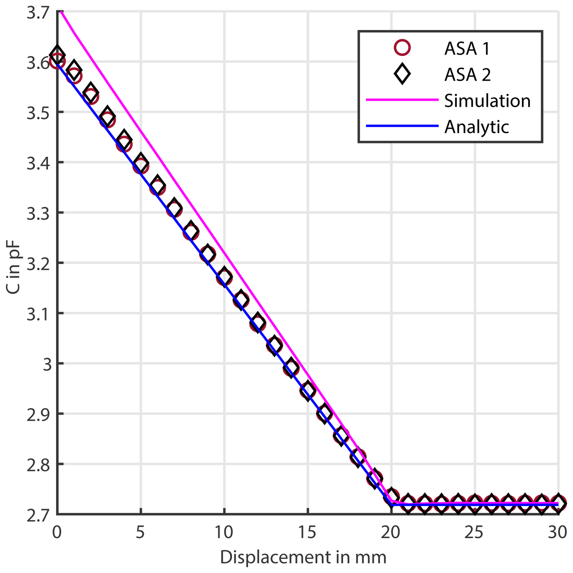
Figure 11Analytical, simulated and measured capacitance of the sensor for different displacements with different ASA pins.
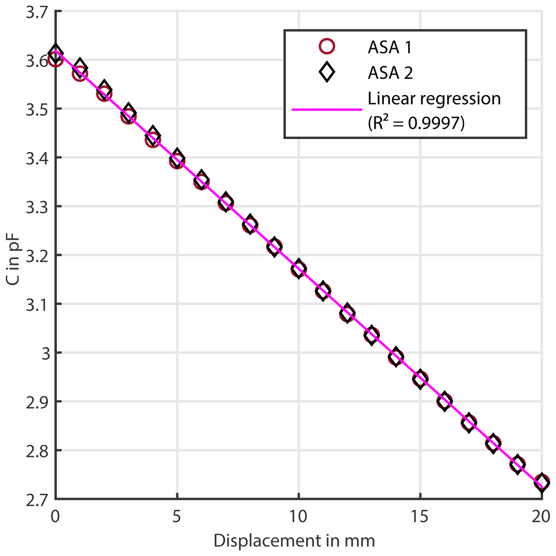
Figure 12Linear regression line for the measured capacitance of the sensor for different displacements with ASA pins.
Table 1Average deviation of the measured capacitance change ΔC from 0 to 30 mm compared to the simulation results.

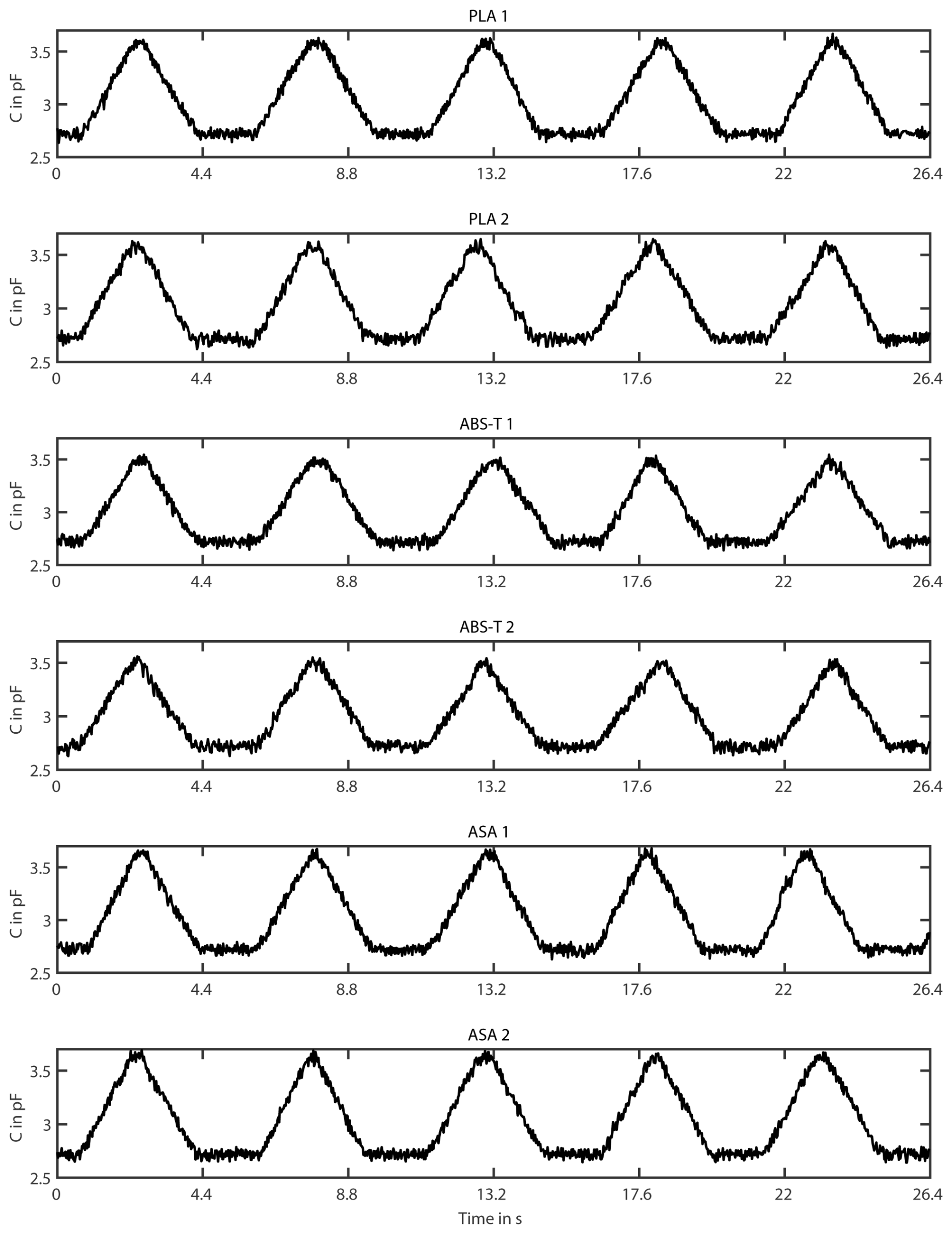
Figure 13Measured capacitance of the sensor for back-and-forth displacements with different pins.
The average deviation of the measured capacitance change between a displacement from 0 to 30 mm compared to the numerical simulation varies with the samples and is shown in Table 1. This deviation stems from deviating material parameters and geometric deviations due to manufacturing tolerances. The assumed εr used for the simulation does not seem to fit in this case, especially for the ASA samples. There are different causes for the deviation: the different printer, filament, material batch, ambient conditions during production or the infill structure. The effect of these parameters on the εr is the subject of further study for more detailed simulation prediction. With the exception of the slope error related to the inaccurate εr, the measurements confirm the simulations. The sensor shows an approximately linear behaviour in the relevant measurement area. The plateau after 20 mm suggests that further displacement does not significantly affect the capacitance, indicating that the guiding electrodes are functional. Capacitance fluctuations at the edges of the sensing electrode due to fringing field effects could be minimised.
Figure 13 depicts the capacitance plotted over time for the six pin samples. All samples show periodic behaviour, indicating the expected repeating pattern in capacitance measurements. Five complete cycles can be seen, indicating stable and regular behaviour. The different materials (PLA, ABS-T and ASA) have similar responses under the conditions measured. The maximum peak is different across the individual materials, which is related to the differing εr of the materials. The amplitude remains constant over the entire series of measurements for one pin, which indicates a consistent physical behaviour of the samples. The lower inflection point is stable over all measurements but shows higher fluctuations than in the previous measurements. In general, the fluctuation is higher, which is due to the dynamic conditions, the higher sampling frequency, the accuracy and the deviation of the speed from the linear guide. Overall, the data indicate consistent behaviour of the samples under the given measurement conditions. The concept presented for 3-D printed capacitive displacement sensors opens up new design possibilities, enabling the development of fully additively manufactured pin grippers with integrated displacement sensors. These sensors can be easily scaled and adapted to a wide range of applications due to the simplified manufacturing process.
A capacitive displacement sensor concept for a pin gripper has been designed, simulated, fabricated and evaluated. This approach, using 3-D printing for manufacturing, enables the creation of fully additive manufactured pin grippers with integrated capacitive displacement sensors. The measurement and simulation results indicate a linear relationship between capacitance and displacement up to around 20 mm, at which point the operating range ends and the capacitance plateaus. The agreement between experimental and simulated data suggests that the simulation model is accurate and reliable for predicting capacitance behaviour in this setup. These results also imply that both samples of each material (PLA, ABS-T and ASA) have consistent properties, leading to nearly identical responses in the experiment. The experimental results confirm the numerical simulations and the functionality of the fabricated sensor for different pin materials.
The data presented in this study are available on reasonable request from the corresponding author.
StS designed the sensor and simulated, fabricated and investigated it. StS prepared the paper, with contributions from all co-authors. All co-authors reviewed and edited the paper.
The contact author has declared that none of the authors has any competing interests.
The publication of this paper was supported by the Open Access Publication Fund of the Offenburg University of Applied Sciences.
Publisher's note: Copernicus Publications remains neutral with regard to jurisdictional claims made in the text, published maps, institutional affiliations, or any other geographical representation in this paper. While Copernicus Publications makes every effort to include appropriate place names, the final responsibility lies with the authors. Views expressed in the text are those of the authors and do not necessarily reflect the views of the publisher.
This article is part of the special issue “Sensors and Measurement Systems 2024”. It is a result of the 22. GMA/ITG Fachtagung Sensoren und Messsysteme 2024, Nuremberg, Germany, 11 to 12 June 2024.
OpenAI's ChatGPT-4 was partially employed for grammatical and spelling corrections without adding or altering the authors' initial content.
This paper was edited by Rainer Tutsch and reviewed by two anonymous referees.
Chang, C.-M., Gerez, L., Elangovan, N., Zisimatos, A., and Liarokapis, M.: On Alternative Uses of Structural Compliance for the Development of Adaptive Robot Grippers and Hands, Front. Neurorobot., 13, https://doi.org/10.3389/fnbot.2019.00091, 2019a. a, b
Chang, C.-M., Gerez, L., Elangovan, N., Zisimatos, A., and Liarokapis, M.: Unconventional Uses of Structural Compliance in Adaptive Hands, in: 2019 28th IEEE International Conference on Robot and Human Interactive Communication (RO-MAN), 1–7, https://doi.org/10.1109/RO-MAN46459.2019.8956340, 2019b. a
Devices, A.: AD7747 24-Bit Capacitance-to-Digital Converter with Temperature Sensor Datasheet, Analog Devices Inc., https://www.analog.com/media/en/technical-documentation/data-sheets/AD7747.pdf (last access: 24 September 2024), 2007. a, b
Dichtl, C., Sippel, P., and Krohns, S.: Dielectric Properties of 3D Printed Polylactic Acid, Adv. Mater. Sci. Eng., 2017, e6913835, https://doi.org/10.1155/2017/6913835, 2017. a
Flintoff, Z., Johnston, B., and Liarokapis, M.: Single-Grasp, Model-Free Object Classification using a Hyper-Adaptive Hand, Google Soli, and Tactile Sensors, in: 2018 IEEE/RSJ International Conference on Intelligent Robots and Systems (IROS), 1943–1950, https://doi.org/10.1109/IROS.2018.8594166, 2018. a
Goh, G. D., Goh, G. L., Lyu, Z., Ariffin, M. Z., Yeong, W. Y., Lum, G. Z., Campolo, D., Han, B. S., and Wong, H. Y. A.: 3D Printing of Robotic Soft Grippers: Toward Smart Actuation and Sensing, Adv. Mater. Technol., 7, 2101672, https://doi.org/10.1002/admt.202101672, 2022a. a
Goh, G. L., Yeong, W. Y., Altherr, J., Tan, J., and Campolo, D.: 3D printing of soft sensors for soft gripper applications, Mater. Today: Proc., 70, 224–229, https://doi.org/10.1016/j.matpr.2022.09.025, 2022b. a, b
Hangst, N., Schroeder, S., Wendt, T. M., Stiglmeier, L., Gawron, P., and Himmelsbach, U. B.: Design of a Grounded Low-Cost Capacitive Liquid Level Sensor for Robotics Applications, especially in the Field of Gastronomy, in: Sensors and Measuring Systems, 21th ITG/GMA-Symposium, 1–5, https://ieeexplore.ieee.org/document/9861884 (last access: 21 September 2024), 2022. a, b
Hassan, M. S., Zaman, S., Dantzler, J. Z. R., Leyva, D. H., Mahmud, M. S., Ramirez, J. M., Gomez, S. G., and Lin, Y.: 3D Printed Integrated Sensors: From Fabrication to Applications – A Review, Nanomaterials, 13, 3148, https://doi.org/10.3390/nano13243148, 2023. a
Hernandez, J., Sunny, M. S. H., Sanjuan, J., Rulik, I., Zarif, M. I. I., Ahamed, S. I., Ahmed, H. U., and Rahman, M. H.: Current Designs of Robotic Arm Grippers: A Comprehensive Systematic Review, Robotics, 12, 5, https://doi.org/10.3390/robotics12010005, 2023. a, b
Hossain, M. J., Tabatabaei, B. T., Kiki, M., and Choi, J.-W.: Additive Manufacturing of Sensors: A Comprehensive Review, International J. Precis. Eng. Manufact. – Green Technol., 12, 277–300, https://doi.org/10.1007/s40684-024-00629-5, 2025. a
Iftekar, S. F., Aabid, A., Amir, A., and Baig, M.: Advancements and Limitations in 3D Printing Materials and Technologies: A Critical Review, Polymers, 15, 2519, https://doi.org/10.3390/polym15112519, 2023. a
Ivanov, V., Andrusyshyn, V., Pavlenko, I., Pitel', J., and Bulej, V.: New classification of industrial robotic gripping systems for sustainable production, Sci. Rep., 14, 295, https://doi.org/10.1038/s41598-023-50673-5, 2024. a
Kalaš, D., Šíma, K., Kadlec, P., Polanský, R., Soukup, R., Řeboun, J., and Hamáček, A.: FFF 3D Printing in Electronic Applications: Dielectric and Thermal Properties of Selected Polymers, Polymers, 13, 3702, https://doi.org/10.3390/polym13213702, 2021. a
Khadkotkar, P. and Mishra, A. K.: Short Review on Gripper System: Introduction, Types and Applications, Int. J. Enhanc. Res. Sci. Technol. Eng., 13, 44–53, 2024. a
Khosravani, M. R. and Reinicke, T.: 3D-printed sensors: Current progress and future challenges, Sensors Actuat. A, 305, 111916, https://doi.org/10.1016/j.sna.2020.111916, 2020. a
Kuzmanić, I., Vujović, I., Petković, M., and Šoda, J.: Influence of 3D printing properties on relative dielectric constant in PLA and ABS materials, Prog. Addit. Manufact., 8, 703–710, https://doi.org/10.1007/s40964-023-00411-0, 2023. a
Mo, A. and Zhang, W.: A novel universal gripper based on meshed pin array, Int. J. Adv. Robot. Syst., 16, 1729881419834 781, https://doi.org/10.1177/1729881419834781, 2019. a
Mo, A., Fu, H., and Zhang, W.: A Universal Gripper Base on Pivoted Pin Array with Chasing Tip: 11th International Conference, ICIRA 2018, Proceedings, Part II, 9–11 August 2018, Newcastle, NSW, Australia, 100–111, ISBN 978-3-319-97588-7, https://doi.org/10.1007/978-3-319-97589-4_9, 2018. a
Xin, Y., Zhou, X., Bark, H., and Lee, P. S.: The Role of 3D Printing Technologies in Soft Grippers, Adv. Mater., 36, 2307963, https://doi.org/10.1002/adma.202307963, 2024. a