the Creative Commons Attribution 4.0 License.
the Creative Commons Attribution 4.0 License.
 | 28 Apr 2026
Towards fully automated metrological traceability in process monitoring: a demonstrator approach highlighting the benefits of Digital Calibration Certificates (DCCs)
Nanine Brunner
Marcus Thomas
Dominic Deuber
Carlo Tiebe
The implementation of automation in the metrological traceability of measurements has been demonstrated to possess considerable potential for enhancing the effectiveness of quality management. This enhancement is achieved by decreasing the necessity for human interaction and reducing the risks associated with manual data processing. For this purpose, it is imperative that all metrological and administrative information in quality certificates be provided in a fully machine-readable and machine-interpretable form. The transition from paper-based calibration certificates to Digital Calibration Certificates (DCCs), which meet these requirements, enables a fully automatic process conformity monitoring system. A demonstrator that monitors the temperature of a process has been developed as an example to illustrate the potential for automation that accompanies the use of DCCs, including in security. The programming code is also published to give a starting point for the reader's own implementation.
- Article
(2559 KB) - Full-text XML
- BibTeX
- EndNote


Quality infrastructure (QI) encompasses the institutional frameworks, policies, and services that ensure that products, processes, and measurements meet recognized standards. It comprises metrology, standardization, accreditation, conformity assessment, and market surveillance (INetQI, 2025). Important stakeholders here are the Federal Institute of Material Research and Testing (Bundesanstalt für Materialforschung und -prüfung – BAM); the German Institute for Standardization (DIN); Deutsche Kommission Elektrotechnik Elektronik Informationstechnik (DKE); the German Accreditation Body (DAkkS); and the Physikalisch-Technische Bundesanstalt (PTB), which is the national metrology institute (NMI) of Germany. In this context, calibration certificates are essential for disseminating measurement reliability and traceability. A certificate is defined as an official document that attests to a fact, often used as a verification document. For instance, a calibration certificate confirms that a measuring instrument has undergone a process of calibration. Evaluating the data from the calibration helps to ensure that the instrument functions with the requisite degree of accuracy and precision, as established by the relevant standards. These certificates have been established in QI for a long time. However, the data from the calibration were traditionally presented in an analog form that is optimized for human readability and interpretation. However, transferring the data, e.g., from the PDF or paper version of the certificate to the user's measurement equipment or data system, and processing it correctly require metrological know-how and well-educated human resources. Consequently, the data from the calibration are often not used to improve measurements taken with the calibrated item. Despite all this, the certificates contain valuable metrological data. Utilizing these data can lead to more precise measurement results and therefore to more effective and resilient processes and an increased yield (Melzer and Brunner, 2025). The transition from analog towards Digital Calibration Certificates (DCCs) represents a key step in the development of a more comprehensive; secure; and, above all, fully automated quality control (Hackel et al., 2017; Engel and Popescu, 2025). Digitization is an indispensable prerequisite for automation. The advent of Digital Calibration Certificates, which are machine-readable, has enabled the utilization of information technology (IT) to facilitate the reading and processing of the data from certificates, as well as the automation of metrological traceability, quality assurance, database maintenance, process monitoring, and reporting, as discussed in Engel and Popescu (2025) Engel (2025), and Foldal (2025). Widespread use of DCCs would result in a reduction in workload for highly compensated personnel, thereby enhancing effectiveness, process yield, and sustainability. Additionally, it mitigates the risk of errors, enhancing the safety and precision of the process (Hackel et al., 2017, 2023).
In the context of the QI Digital initiative of the German Federal Ministry for Economic Affairs and Energy, the aforementioned stakeholders within the national quality infrastructure of Germany are pursuing a shared objective, namely the digitization of pertinent tasks and documents, thereby facilitating their automation. In the context of this project, BAM has developed a demonstrator to showcase the benefits of the DCC and the automated verification and utilization of calibration certificate data based on the example of thermal process monitoring. This work delineates the demonstrator and its development, provides the link to the published software, and explores its further applications.
The structured nature of the XML (Extensible Markup Language) data structure, a well-established markup language, enables the storage of all content in a machine-readable manner. This offers a significant opportunity for automation. Additional use cases from industrial and metrological practice further illustrate the benefits of DCCs for automation, data integrity, and digital quality infrastructures in Engel (2025), Foldal (2025), Mustapää et al. (2024), and Kan et al. (2024).
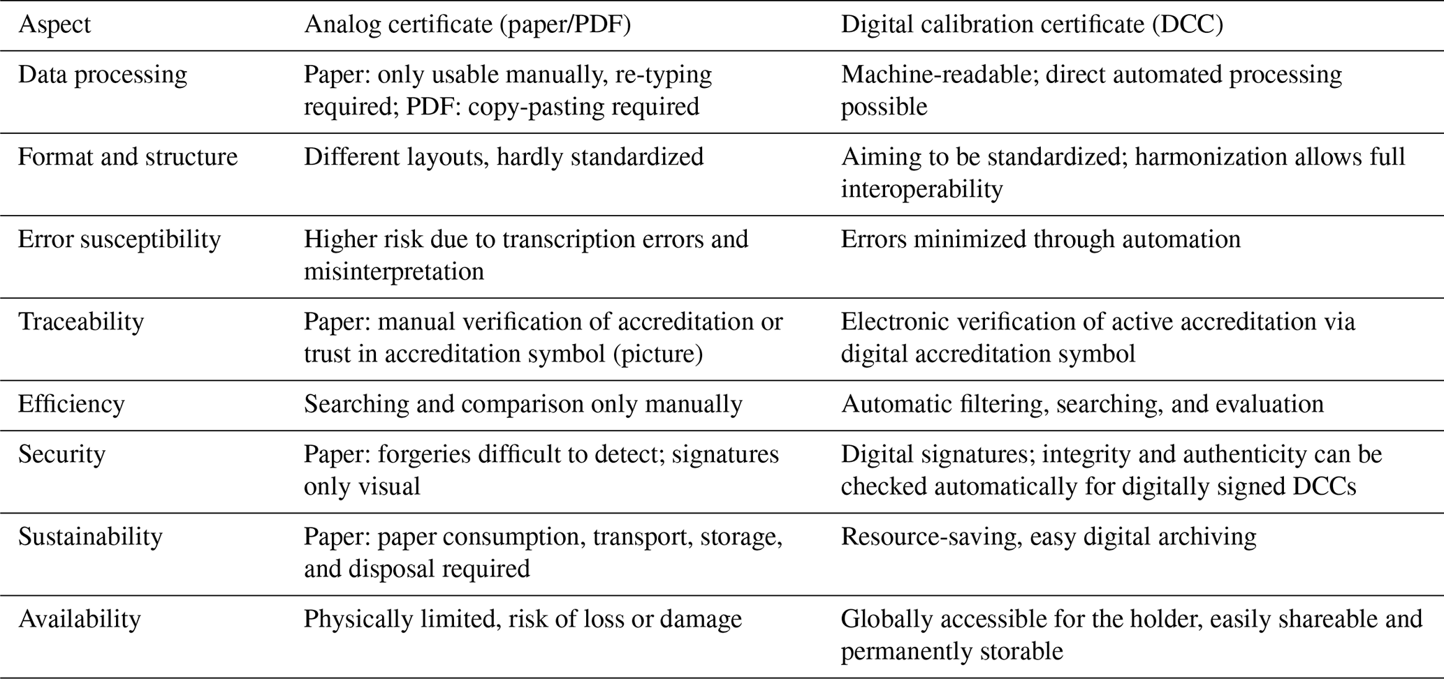
The merits of DCCs become most evident when the entire process chain is taken into consideration. Subsequent to the calibration process, the laboratory will issue a calibration certificate. In the analog case, it is typically provided as a paper document or PDF, which necessitates manual handling and data transfer – on both ends, for the creation of a calibration certificate as for utilizing the data on the user's side. The latter in particular is often laborious, prone to errors, and necessitates staff members who possess the necessary expertise. That is why these analog certificates are merely stored as documentation of compliance, with the contained measurement data remaining unused. Conversely, the DCC comprises the calibration results, encompassing measurement values and uncertainties, as well as metadata such as customer and device information, in a harmonized, machine-readable format. This enables the automation of reading out the data, thereby ensuring the seamless integration of data into management systems. Recent work in the field demonstrates that DCCs are a key enabler for the digital transformation of metrology and quality infrastructures (Hackel et al., 2017; Engel and Popescu, 2025; Schönhals et al., 2025a). This integration eliminates transcription errors, reduces the necessity of manual intervention, and significantly reduces personnel costs, as summarized in Table 1. These advantages will be particularly evident as soon as the DCC is further standardized. Such harmonization efforts are currently coordinated by the German Calibration Service (DKD), for example (Melzer et al., 2025). Using data from the DCC allows for the automated correction of measurements. Also, a comprehensive uncertainty calculation can automatically be performed by accounting for uncertainties from calibration. This enhances the accuracy and reliability of measurement results. Additionally, verification through software without requiring specialized user expertise is enabled. Consequently, DCCs effectively transition calibration certificates from static documents to dynamic components of automated workflows. This empowers organizations to ensure compliance, enhance efficiency, reduce costs, and improve data quality throughout the measurement process. Realizing these advantages requires a harmonized structure. The DCC schema, hosted by the PTB (Physikalisch-Technische Bundesanstalt – PTB, 2025c), provides such a structure, while refTypes attributes ensure consistent and interpretable data across systems. The next section introduces these essential components.
Table 1Comparison of analog calibration certificates and Digital Calibration Certificates (DCCs).
The goal is to establish a standard that allows software to automatically read data from any calibration laboratory's DCC. For the data to be machine-readable, software must be able to locate and read specific information in a document. This requires that the data be stored in a structured way, which is provided by the XML format. However, it is important to note that the structure must also be harmonized.
The DCC schema hosted by PTB (Physikalisch-Technische Bundesanstalt – PTB, 2025c) provides the structure and terminology required in the XML document. The general schema can be found under Physikalisch-Technische Bundesanstalt – PTB (2025d). Schönhals et al. (2025a) and Hackel et al. (2021) provide a comprehensive overview of the structure and organization of the DCC schema. For more information please consult the DCC wiki (Physikalisch-Technische Bundesanstalt – PTB, 2025a) and the website for the schema version 3.2.1 (Physikalisch-Technische Bundesanstalt – PTB, 2025e).
For specific information to be machine-interpretable, the software handling the DCCs must be able to locate and address it explicitly. The DCC schema defines some unique tag elements for this purpose (Schönhals et al., 2025b). Mandatory key information in a common DCC, such as the performance date or the unique identifier, is stored in tag elements that only exist once (Melzer et al., 2025), such as under tags named <dcc:endPerformanceDate> and <dcc:uniqueIdentifier>, respectively. Therefore, it can easily be addressed and processed because its meaning is clear. However, the majority of the DCC schema is structured into sections that allow for tag elements with the same name, even at the same hierarchical level. For instance, the measurement results for the reference sensor and the calibration item, for example, expressed in Kelvin, are both stored in an <si:valueXMLList> element, each wrapped by <dcc:quantity>, as shown in Fig. 1 (see also Listing 3). Therefore, the key measurement data are not unambiguously addressable. However, including the refType attributes <dcc:quantity refType=“basic_referenceValue”> and <dcc:quantity refType=“basic_measuredValue”>, respectively (shown in yellow in Fig. 1), makes the information distinguishable and thus clearly addressable. Since the refType attributes also provide the dedicated semantics for the specific information found in their respective <dcc:quantity>, those values also become interpretable by an algorithm.
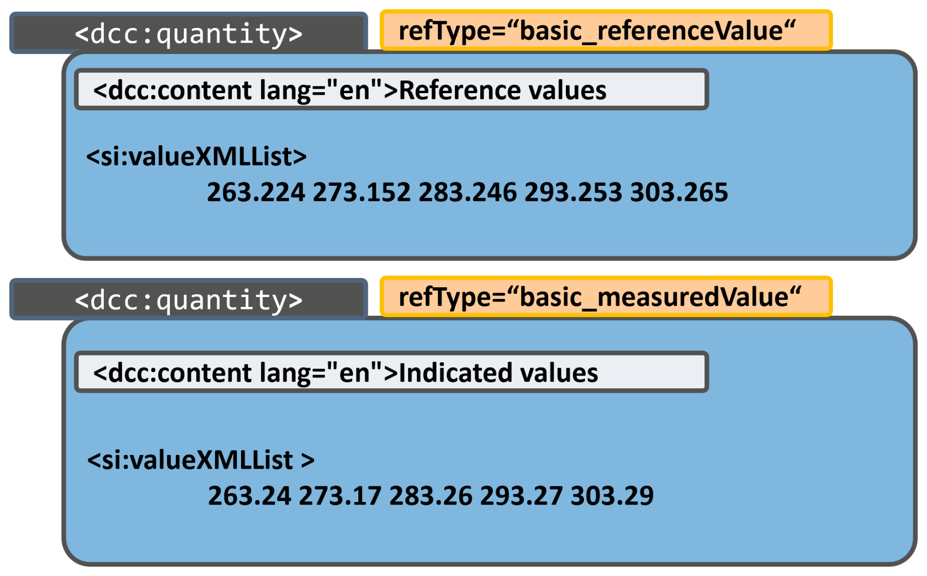
Figure 1Usage of RefTypes: the measurement data from the reference sensor, as well as from the sensor to be calibrated, are stored in a tag named “valueXMLList”. Each is wrapped in a separate “dcc:quantity” tag, which makes it so that it is not unambiguously addressable. The refTypes in yellow function as markers on the way to the information providing the desired semantics.
For this to work in an interoperable way, the refTypes also need to be harmonized. The German Calibration Service (Deutscher Kalibrierdienst – DKD) is hosting a thesaurus website (see Deutscher Kalibrierdienst – DKD, 2025) for exactly this purpose. It serves as a comprehensive resource, providing a detailed list of general and community-specific refTypes, along with their intended applications, hints, and permissible schema positions.
The advantages of Digital Calibration Certificates as delineated in the preceding chapters frequently remain untapped. This is partly due to a lack of knowledge regarding how to enable the full potential of data usage from the calibration certificates, in general, on the user's site and partly because the DCC is not yet sufficiently established and standardized. In an effort to address the existing knowledge gap and to disseminate the principles of the DCC, a demonstrator was developed at BAM, which showcases the automated DCC validation, metrological traceability, and quality-assured process conformity monitoring – at the push of a button. The following sections describe how all steps, from measurement data collection and their visualization to DCC import, validation, calibration data collection and its utilization for measurement correction and uncertainty determination, are performed fully automatically and also highlight the economic potential of traceability in quality-assured industrial metrology.
4.1 Hardware and scenario
The fundamental idea behind the demonstrator is to simulate a simple process which has a defined critical thermal window (e.g., [0 to 2] °C in a production line). Hence, the quality-assured conformity of the process with respect to these boundary conditions has to be monitored. In terms of quality management, an accredited calibration service provider is commissioned for the recurrent calibration of the entire temperature measurement chain (i.e., probes, signal acquisition unit, and temperature display) within a defined recalibration interval. The configuration outlined below was implemented for this purpose, as also depicted in Fig. 2:
-
Arduino (connectable to PC/laptop) with up to 4 Pt100 temperature sensors connected;
-
an optional thermostat providing a stable temperature to be monitored;
-
a DCC for each of the four sensors (calibration and creation of these DCCs took place in our calibration laboratory);
-
in terms of IT-infrastructure, the components included are
-
GUI as control panel for the user,
-
Code to process and display the measurement values and their specification,
-
Code to load DCC and read out its data, calculate a regression function and determine the uncertainty in application,
-
Code to display the results of the validation, the corrected values and the conformity.
-
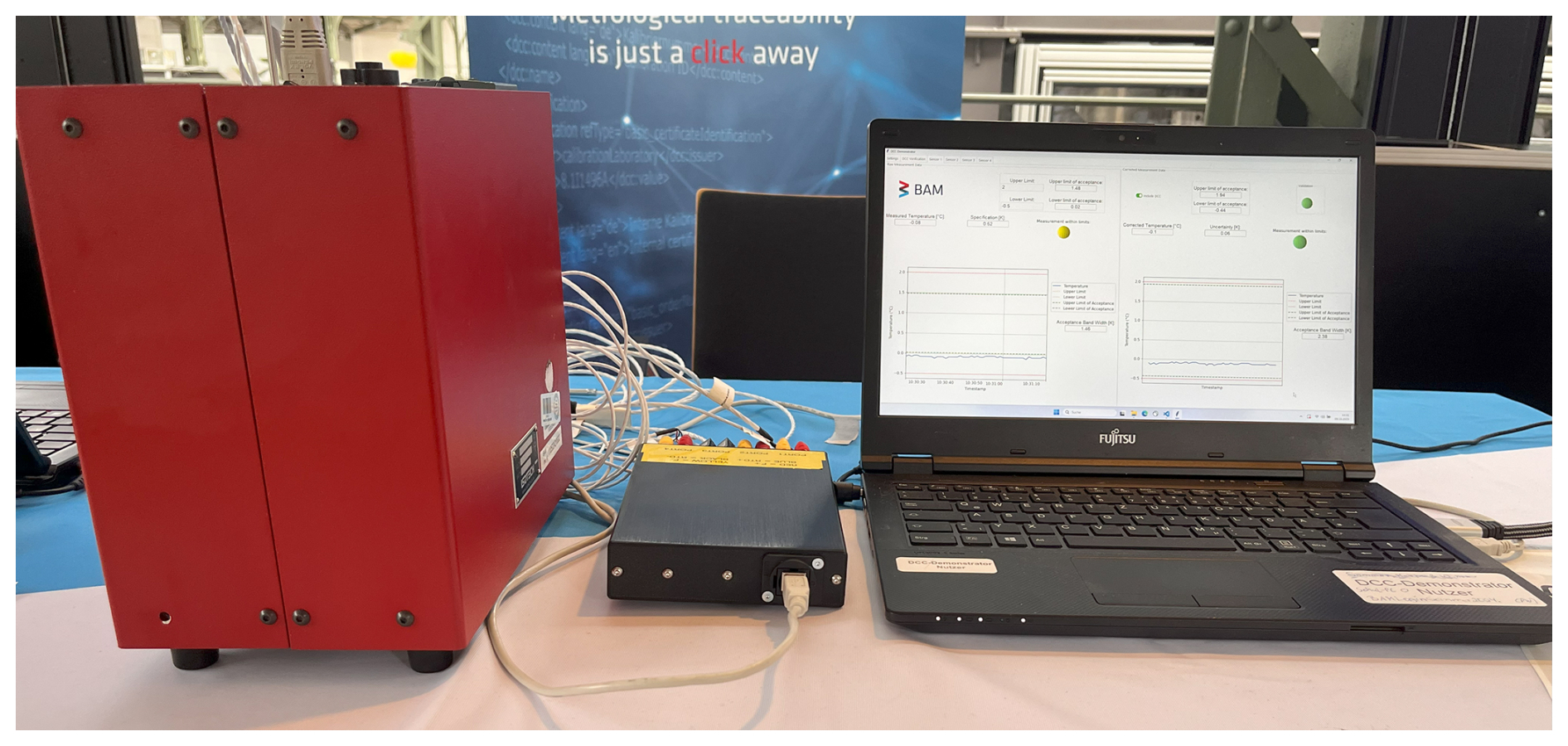
Figure 2Setup for the demonstrator. The small black box situated centrally within the apparatus contains an Arduino microcontroller. The four temperature sensors are connected to the Arduino. The bigger red box provides a constant temperature of 0 °C for sensors which should measure a stable temperature. The Arduino is connected to the laptop where the demonstrator program is running via USB.
The demonstrator software is entirely implemented in Python. The functional source code can be found at https://doi.org/10.5281/zenodo.18963210 (Brunner, 2026).
4.2 Basic measurement and process monitoring
Following the initiation of the demonstrator software, a measurement can be started through the selection of either live or simulation mode. The latter is implemented in order for the demonstrator to be usable without any hardware connected. Subsequently, the temperature reading will be plotted on the left side of each of the four sensor tabs. The user can set the intended process limits (upper and lower) on each sensor tab separately and independently to consider a dedicated measurement task for each of the four sensors. Figure 3 shows the GUI of the demonstrator, displayed on one of the measurement tabs. The measurement of sensor 1 is plotted on the left. The manufacturer's specification for each element of the measuring chain must be considered as an expression of uncertainty when no calibration is taken into account in terms of quality assurance (for critical process properties). The “limits of acceptance” are determined by calculating the upper and lower limits by subtracting the specification from the set upper process limit and adding it to the lower process limit since, beyond these boundaries, a process conformity cannot be guaranteed. This substantially limits the width of the acceptance window from the temperature reading. The LED display indicates by color whether the measurement is within the established limits of acceptance.
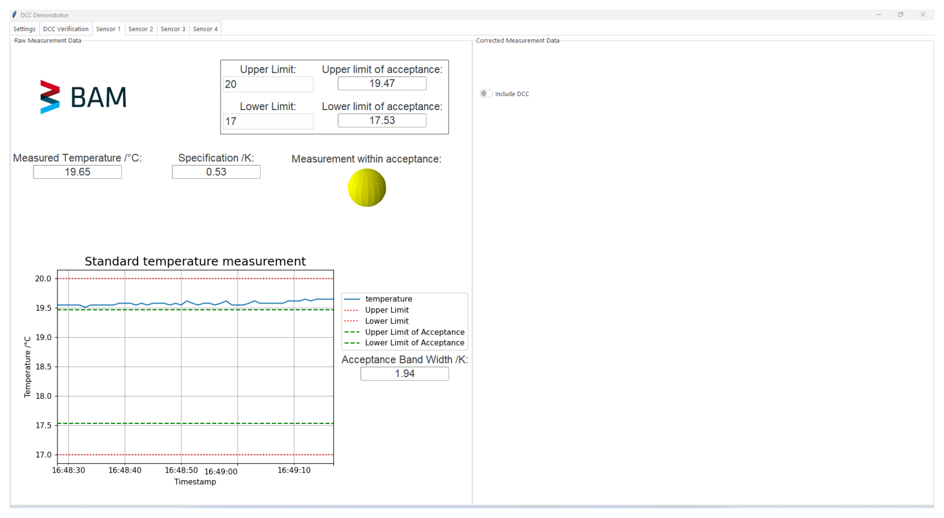
Figure 3GUI of the DCC demonstrator. Measurement without taking into account the data from the calibration certificate. The specification must be taken into account instead of an uncertainty. The LED indicates by color whether the current measurement value is within limits (green – within acceptance; red – out of limits; yellow – in uncertainty zone between acceptance and hard limit).
4.3 DCC receipt and automated validation
Upon reception, a calibration certificate is required to undergo a series of security checks to ensure the reliability of the data, its integrity after calibration, and its provenance. In the case of an analog certificate, the user is required to execute these checks manually. Conversely, in the context of a digital certificate, DCC-processing software may execute all checks automatically, thereby enabling the DCC to attain its maximum potential in terms of automation and security. These measures have been incorporated into the demonstrator program.
A DCC file can be incorporated into the demonstrator software simply by dragging and dropping it into the designated frame in the DCC verification tab. This initiates the automatic verification procedure for this particular DCC, which is sequentially described in the following sections. Colored LEDs display the result of each verification step in real time, as shown in Fig. 4. In addition, short text outputs occur, briefly describing the meaning of each verification step result or issue that may occur and further information (not shown here).
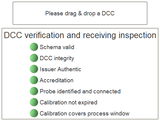
Figure 4Short summary display of the validation status of the currently loaded DCC in the demonstrator program.
The functions for these checks are all in the DCCvalidation.py script for further inspections.
4.3.1 Schema validation
Ensuring that data can be read from a DCC by software is contingent upon its compliance with the DCC schema (Physikalisch-Technische Bundesanstalt – PTB, 2025c). In the demonstrator, this is verified automatically using the functions defined in the DCCvalidation.py script. The version of the schema utilized and the link to the XSD schema source hosted by the PTB are generally provided as attributes in the preamble of a DCC, as illustrated in Listing 1.

This information is read out using XPath, a language for addressing information in XML documents, and the schema is downloaded and stored locally. Subsequently, the DCC structure is compared with this schema version via the validate function within the Python module xmlschema. Since the version of the schema and its PID are listed in the DCC, the entire check can be performed automatically without any further action on the user side. However, it should be noted that the schema validation is a pure structural and terminology check and does not consider content or logical aspects.
4.3.2 Validation of integrity, authenticity, and accreditation status
If a DCC is digitally signed, its integrity and authenticity can be automatically validated, along with the accreditation status of the laboratory that created the DCC, depending on the type of signature. In general, a digital signature ensures the integrity and authenticity of the signed data. “Integrity” means that the data have not been altered since signing, while “authenticity” means that the data actually originate from the signing party. In order to understand the authenticity, it is necessary to understand how digital signatures are generated. A digital signature scheme consists of a public key and a secret key. The secret key is used to generate the signature and must be kept secret by the signing party at all times. The public key allows anyone to validate the digital signature. A public key certificate links the public key to the identity of the signing party, e.g., the name of a legal person in case of an electronic seal. A public key certificate may also contain additional attributes – such as accreditation information. The German accreditation body (Deutsche Akkreditierungsstelle GmbH, DAkkS) issues specific public key certificates to its accredited conformity assessment bodies (CABs). These public key certificates contain a digital accreditation symbol as a digital national emblem that allows the body’s accreditation status to be verified. Consequently, the integrity and authenticity of an attestation, such as the DCC, and the accreditation status of the attesting conformity assessment body can be validated digitally, worldwide, and in real time. While, in technical terms, the DCC is digitally signed and DAkkS issues the required certificate, in legal terms, the DCC is sealed with an advanced electronic seal and DAkkS issues a qualified seal certificate (cf. Art. 3 (26) and (30) of Regulation (EU) No. 910/2014). The Trust Service Practice Statement (TSPS) of DAkkS (see Deutsche Akkreditierungsstelle GmbH – DAkkS, 2025) outlines the process for verifying the validity of the digital accreditation symbol and, thus, the accreditation status of the CAB. Moreover, it also provides references regarding the standards and background essential for securing DCCs and the used methods. Five checks are required in order to fully verify the sealed DCC (one form of eAttestation1), which will be outlined below. First, the signature must be validated using the public key contained in the public key certificate, which is typically embedded in the DCC. This verifies that the checksum generated with the content of the DCC during sealing still matches with the checksum of its current content. Hence, it justifies that the content was not altered (intentionally or not) since the authorization by the issuing body (data integrity). Second, the current time, i.e., the time at which the signature is being checked, must fall within the public key certificate's validity period. Digital public key certificates expire after a certain period (here, 2 years), after which a new certificate must be applied for. Third, it must be checked that the public key certificate has not been revoked. If accreditation has been suspended or withdrawn, DAkkS will also revoke the digital public key certificate. Fourth, the public key certificate path must be verified; i.e., the first three checks must be performed for every certificate on the path up to the trusted root certificate. To understand this step, it is helpful to take a closer look at digital public key certificates. As outlined above, a digital public key certificate links a public key to an identity. This is achieved through a digital signature: the information that a public key belongs to a specific identity is signed by another public key, which may itself be contained within another certificate, and so on. At some point, a trusted root certificate is accepted as a trust anchor. The chain of signatures leading up to this root certificate is then validated. Finally, the public key certificate must contain the digital accreditation symbol, which is verified by checking for the Object Identifier (OID) to carry the following content: 1.3.6.1.4.1.59749.1.
These five steps are checked automatically in the demonstrator program. As soon as a DCC is dragged into the system, the outcome is displayed by the three LEDs corresponding to the main functionalities of the digital accreditation symbol, namely “DCC integrity”, “Issuer Authentic”, and “Accreditation”.
4.3.3 Further receiving inspection
After validating the schema conformity and the electronic seal, further balancing with system parameters is performed in the demonstrator before the DCC data are actually processed. A DCC contains metrological data of one particular temperature sensor probe that was calibrated. In order to achieve metrological traceability of the measurement results, the dragged DCC has to be linked to that particular probe. In the demonstrator, it is not necessary to do this manually. If a DCC contains an identifier of the respective calibration item at the designated location, it can be addressed and extracted by the algorithm and compared to the list of probes that are known to the system (i.e., a measuring equipment database). If the match is positive, the system recognizes if this particular probe is actually connected and provides plausible temperature readings. The result of this check is displayed via the “probe identified and connected” LED in the verification summary. Hence, this important linkage of DCC to the item is also fully automated. As a next validation step, the performance date of the calibration service is extracted from the DCC and compared to the recalibration interval defined in the system. If the calibration is too long ago, a more recent DCC should be used, or the probe needs to undergo recalibration. This is indicated by the “calibration not expired” color LED. Furthermore, if the calibrated interval does not cover the measurement task of the probe, metrological traceability cannot be achieved. Therefore, a final balancing is made between the calibrated interval reported in the DCC and the upper and lower process limits defined for the respective sensor in the demonstrator software. The result is indicated by the “calibration covers process window” LED in the verification summary board (Fig. 4).
This entire validation protocol ensures the secure and plausible operation of the DCC data in the demonstrator software. In case one of the steps fails, the DCC cannot be processed properly. In some of the cases, e.g., the expiration of the recalibration interval, the user may decide to still use the DCC data for further processing, temporarily, keeping in mind that their own quality management regulations are violated. In real-world DCC-processing use cases, further plausibility checks and balancing of information between the DCC and the quality management environment may be necessary and useful (e.g., concerning uncertainty requirements, influence conditions, or used methods) prior to DCC utilization. Most of them are able to be validated automatically. The simple checks implemented in the demonstrator software consider some key aspects only in order to demonstrate the concept and automation potential.
4.4 Measurement value correction and calculation of uncertainty in use
A DCC can be validated and, in the case of passing the checks described in the former sections, included in the process monitoring in two ways:
-
by dragging and dropping a DCC into the respective field of the “DCC verification” tab
-
by activating the “include DCC” switch in the respective sensor tab.
Both actions trigger the fully automatic validation process as described in the previous chapters.
When the validation of the DCC is completed and all checks are passed (all LEDs are green like in Fig. 4) the DCC is implemented in the demonstrator program, and the required data are read out and processed. In this context, the schema and the refTypes gain particular significance. As discussed in Sect. 3, the measurement data are not unambiguously addressable without refTypes. In general, a specific tag can be addressed using xpath (for an introduction, see w3schools, 2025). For a unique tag, for example , <dcc:endPerformanceDate>, the XPath expression is given in Listing 2.

It should be noted that the namespace must be properly specified as the Python module etree is employed in the handling of the XML document, which represents the DCC.
The tags for the measurement data of the reference sensor and the calibrated sensor have the same name. Listing 3 shows the block for the data of the reference sensor in the DCC. The one for the calibrated sensor looks the same in terms of structure and tag naming (see also lines 262 to 693 in the DCCs that come with the published code).
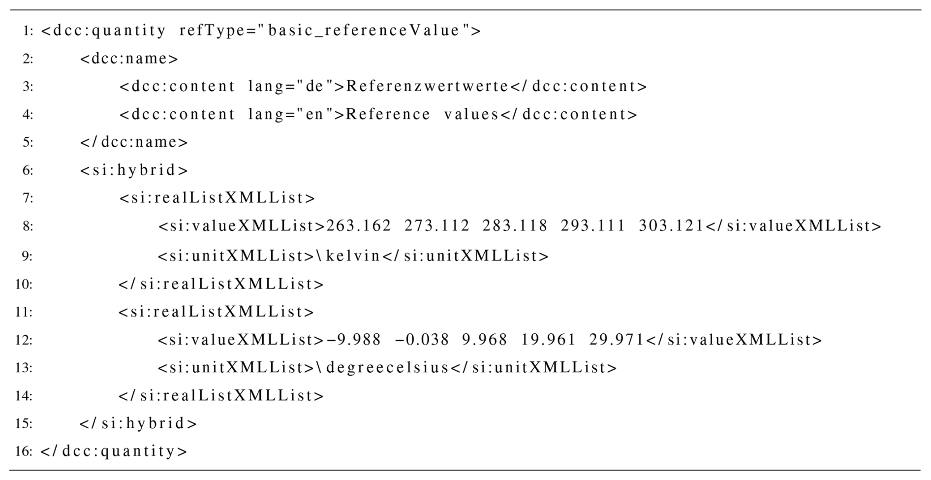
In addition to the issue of distinguishing the two datasets, the software needs to find the <si:valueXMLList> tag with values in the desired unit, as shown in Listing 3. Both problems can be addressed using XPath, as shown in Listing 4.
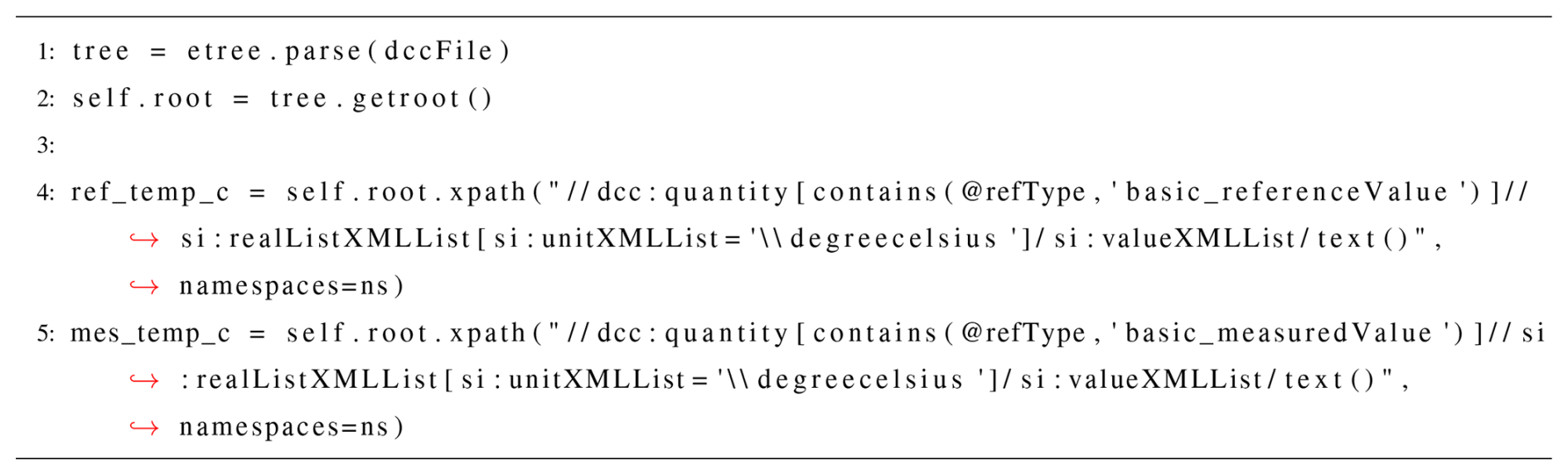
Once the measurement data are read out, these are used to calculate a regression function using curve_fit from the Python module scipy.optimize. With this function, the corrected value for each and every single measurement value within the calibrated range will be calculated – in real time – and fully automated. In addition to the measurement values of the reference and the calibrated sensor, the uncertainty values for each measuring point are also read out. The expanded uncertainty in use is calculated by extending the calibration uncertainty with further contributions that arise from the actual measurement scenario and sensor usage according to Eq. (1), where ucal is the uncertainty associated with the respective measured value from the calibration; uhyst is the uncertainty contribution caused by hysteresis; and ureg is the contribution introduced by the regression line, i.e., to account for residual errors of the correction.
In the BAM calibration laboratory, hysteresis is not measured but estimated as a lump sum according to the DKD-R 5-1 calibration rule (Physikalisch-Technische Bundesanstalt – PTB, 2025b). The remaining uncertainty contributions are contingent upon the prevailing measured value. Please refer to the example DCC in the GitHub repository to access the list of uncertainty values for the calibration. The uncertainty contribution originating from the regression consists of a contribution for the intercept a and the slope b. Every uncertainty contribution consist of the uncertainty of the influencing factors si and a sensitivity factor ci, as shown in Eq. (2).
In the above, si is the uncertainty, ci is the sensitivity factor in relation to the respective quantity i, and sR is the standard deviation for the regression function with the sensitivity factor cR. The expanded uncertainty is calculated by taking the coverage factor k into account according to Eq. (3).
While most of the terms are constant over the calibrated range, the following depend on the current temperature measurement value: scal (from the calibration certificate) and cb (has to be recalculated continuously). In the demonstrator program, these calculations are performed in real time and automatically for each measurement value of each of the four sensors. The basic equations for the constant terms are defined in the Sensoren.py script (in the calc_correction function). The continuous calculations take place in the Main.py script in the update function. Once all relevant variables have been calculated, the very same function triggers the publication of an event that updates all of the output fields and also the plots in the GUI. For a closer look and a deeper understanding, please refer to the published and referenced code. As a result the basic temperature measurement displayed on the left site of the demonstrator GUI (as shown in Fig. 3) is extended, as presented in Fig. 5. The same measurement is displayed on the right, but, here, data from the corresponding DCC are taken into account as described above.
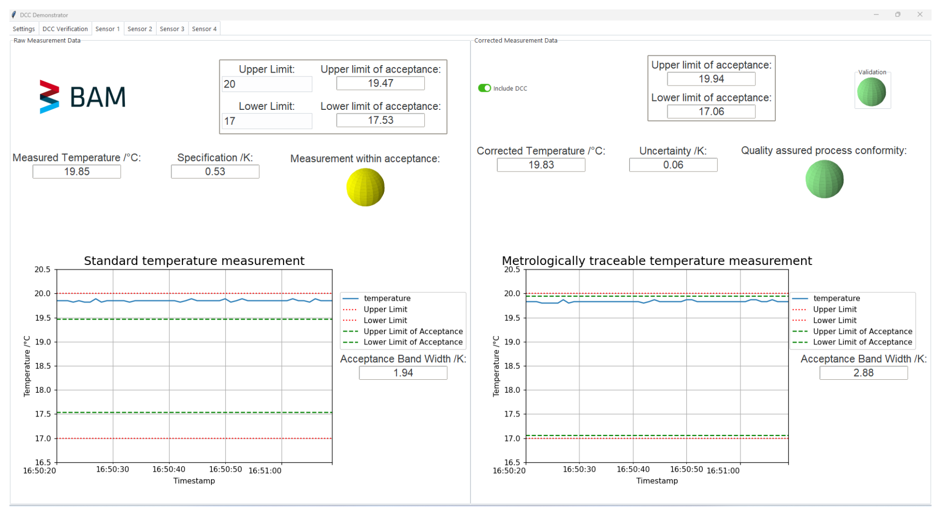
Figure 5User interface of the demonstrator. On the left-hand side, the measurement without the use of calibration data is shown. It relies on the manufacturer's specifications. On the right-hand side, the same measurement is shown, taking into account the calibration data. This results in a more accurate measurement with a smaller uncertainty and, thus, a wider temperature acceptance range for the process.
The right side is only displayed after the corresponding DCC has passed the validation tests described in Sect. 4.3, indicated by the green validation LED on the upper-right side. In the case of a minor validation check violation, like described in Sect. 4.3.3, the validation LED would be displayed in red, indicating that the validation checks have not all been passed. In the event of a DCC being integrated but the temperature measurement values leaving the calibrated range, the program would automatically conceal the right side of the sensor tab. For the time of the measurement values being out of the calibrated range, the DCC is excluded, and the data are not utilized. Consequently, the measurement values lack metrological traceability.
Using the demonstrator program reveals that measurements taken with one of the sensors can be improved by using DCC data. On the left side of the sensor tab, the measurement is shown without utilizing the calibration data. The process acceptance range, with limits set by the user, becomes smaller when the specification is included. Assuming the process is temperature-controlled, any measurement point within the uncertainty range (i.e., between the acceptance and process limits) may result in the rejection of produced goods or a retest being necessary to ensure that the goods meet the quality requirements. On the right side, the very same measurement is displayed, only with utilization of the data from the DCC. All of the above calculations are performed in the background and without any user interaction. The user only needs to drag and drop the DCC file into the system or, alternatively, flip the “include DCC” switch on the desired sensor tab. Using the DCC data increases the trueness of the measurement result by means of correction and, at the same time, reduces uncertainty, hence also widening the effective acceptance window of the process so that fewer produced goods need to be rejected or retested. In a production line, this may have a direct economical impact.
The development of a demonstrator that elucidates the advantages of the utilization of calibration data in a simple and clear manner has been successful. Since all steps, from measurement recording and DCC validation to the evaluation and use of the calibration data, are fully automated, the user does not need any specialized metrological knowledge or to actually understand the content of the DCC. All this was accomplished without the involvement of IT specialists or computer engineers. Since the entire code of the demonstrator is available, potential users can gain an overview of the complexity of the implementation and see the advantages for their own use cases to support the necessary IT development process. The provided program code can also serve as an inspiration for algorithms in real applications, although it might only be a starting point for others to develop their own software for DCC handling for integrated quality assurance of observed process data.
The code is available at https://doi.org/10.5281/zenodo.18963210 (Brunner, 2026).
No data sets were used in this article.
NB was responsible for writing the programming code and writing this paper. MT was in charge of performing the calibrations in the calibration laboratory at BAM. DD from DAkkS consulted on the code for the security checks of the DCC validation and contributed a part of the validation section. MM is head of the calibration laboratory at BAM and contributed a part of the validation section in the paper. CT is the QM representative of the calibration laboratory and revised the paper.
The contact author has declared that none of the authors has any competing interests.
The author, Dominic Deuber, is an expert in emerging technologies | Cybersecurity at the Deutsche Akkreditierungsstelle GmbH (DAkkS). The article reflects solely his scientific opinion and not necessarily the position of DAkkS. Although the code is publicly available and reuse is permitted, please note that, if doing so, the provided code has been developed for demonstration purposes, and, although attention has been paid to accuracy, functionality, and security, the occurrence of security vulnerabilities cannot be ruled out when implementing in a real application.
Publisher's note: Copernicus Publications remains neutral with regard to jurisdictional claims made in the text, published maps, institutional affiliations, or any other geographical representation in this paper. The authors bear the ultimate responsibility for providing appropriate place names. Views expressed in the text are those of the authors and do not necessarily reflect the views of the publisher.
This article is part of the special issue “Sensors and Measurement Science International SMSI 2025”. It is a result of the 2025 Sensor and Measurement Science International (SMSI) Conference, Nuremberg, Germany, 6–8 May 2025.
The authors would like to thank all of their colleagues in Division 8.1 at BAM for providing valuable feedback during the development of this work. Special thanks go to Keerthana Nattuveettil, whose support and discussions contributed greatly to the implementation and refinement of the presented approach.
This work was supported by the QI Digital Project. QI-Digital is an initiative by BAM, DAkkS, DIN, DKE, and PTB, funded by the Federal Ministry of Economic Affairs and Energy (BMWE).
This paper was edited by Michele Penza and reviewed by two anonymous referees.
Brunner, N.: DCC Utilization and Automation Demonstrator, Zenodo [code], https://doi.org/10.5281/zenodo.18963210, 2026. a, b
Deutsche Akkreditierungsstelle GmbH – DAkkS: https://accreditationauthority.dakks.de/pki/dakks-tsps-en.pdf, last access: 16 September 2025. a
Deutscher Kalibrierdienst – DKD: TemaTres for refTypes, https://digilab.ptb.de/dkd/refType/vocab/index.php, last access: 4 September 2025. a
Engel, T. and Popescu, A.: GEMIMEG – Digitalization of calibration processes in metrology, Measurement: Sensors, 38, 101474, https://doi.org/10.1016/j.measen.2024.101474, 2025. a, b, c
Engel, T.: From a digital calibration certificate to a digital quality infrastructure, EPJ Web Conf., 323, 01003, https://doi.org/10.1051/epjconf/202532301003, 2025. a, b
Foldal, H.: Digitalization in the metrology quality infrastructure – perspectives from Novo Nordisk, EPJ Web Conf., 323, 01002, https://doi.org/10.1051/epjconf/202532301002, 2025. a, b
Hackel, S., Härtig, F., Hornig, J., and Wiedenhöfer, T.: The digital calibration certificate, PTB – Mitteilungen Forschen und Prufen, 127, 75–81, 2017. a, b, c
Hackel, S., Härtig, F., Schrader, T., Scheibner, A., Loewe, J., Doering, L., Gloger, B., Jagieniak, J., Hutzschenreuter, D., and Söylev-Öktem, G.: The fundamental architecture of the DCC, Measurement: Sensors, 18, 100354, https://doi.org/10.1016/j.measen.2021.100354, 2021. a
Hackel, S., Schönhals, S., Doering, L., Engel, T., and Baumfalk, R.: The Digital Calibration Certificate (DCC) for an End-to-End Digital Quality Infrastructure for Industry 4.0, Sci, 5, https://doi.org/10.3390/sci5010011, 2023. a
INetQI: https://www.inetqi.net/documentation/quality-infrastructure-definition/, last access: 8 September 2025. a
Kan, K., Wang, S., Liu, Z., and Xiong, X.: Design and Implementation of Digital Calibration Certificate for RFID Tag Storage, Sensors, 24, https://doi.org/10.3390/s24206626, 2024. a
Melzer, M. and Brunner, N.: Digital Certificates: Enabling Automation in Quality Assurance and Metrological Traceability, in: SMSI 2025: Lectures, C6 – Hydrogen Sensor Technology, AMA Service GmbH, 171–172, ISBN 978-3-910600-06-5, https://doi.org/10.5162/SMSI2025/C6.4, 2025. a
Melzer, M., Deschermeier, R., Bünger, L., Wroblowski, O., Demir, M.-A., Bubser, F., and Schüür, J.: The DCC for temperature and humidity quantities: good practice for enhanced interoperability, Measurement, 263, 120109, https://doi.org/10.1016/j.measurement.2025.120109, 2025. a, b
Mustapää, T., Koskinen, S., Sundfors, M., Jonsson, J., Riska, K., Löytynoja, L., and Broo, J.-A.: Enabling the use of digital calibration certificates in industrial calibration management systems, J. Sens. Sens. Syst., 13, 71–79, https://doi.org/10.5194/jsss-13-71-2024, 2024. a
Physikalisch-Technische Bundesanstalt – PTB: https://wiki.dcc.ptb.de/, last access: 4 September 2025a. a
Physikalisch-Technische Bundesanstalt – PTB: Calibration of resistance thermometers: Guideline DKD-R 5-1, PTB, https://doi.org/10.7795/550.20231207, last access: 9 October 2025b. a
Physikalisch-Technische Bundesanstalt – PTB: https://www.ptb.de/dcc/, last access: 4 June 2025c. a, b, c
Physikalisch-Technische Bundesanstalt – PTB: https://www.ptb.de/dcc/v3.3.0/autogenerated-docs/Doku%20Oxygen%203.3.0.html, last access: 4 September 2025d. a
Physikalisch-Technische Bundesanstalt – PTB: https://www.ptb.de/dcc/v3.2.1/dcc.xsd, last access: 4 September 2025e. a
Schönhals, S., Demir, M.-A., Doering, L., Gloger, B., Hackel, S., Heeren, W., Jagieniak, J., Jordan, M., Keilholz, C., Krah, T., Loewe, J. H., Mienert, K., and Öktem, G. S.: Harmonisation processes and practical implementation of machine-interpretable digital calibration certificates, Measurement: Sensors, 38, 101470, https://doi.org/10.1016/j.measen.2024.101470, 2025a. a, b
Schönhals, S., Jordan, M., Melzer, M., and Röske, D.: Ideas for the transition from paper-based force and torque calibration certificates to machine-readable XML data, Measurement: Sensors, 38, 101334, https://doi.org/10.1016/j.measen.2024.101334, 2025b. a
w3schools: https://www.w3schools.com/xml/xpath_intro.asp, last access: 10. September 2025. a
The eAttestation is any kind of an attestation (according to the ISO/IEC 17000 definition) in a digital format (e.g., XML or PDF) that entails a digital accreditation symbol (e.g., the DAkkS digital accreditation symbol in form of a digital seal).