the Creative Commons Attribution 4.0 License.
the Creative Commons Attribution 4.0 License.
 | 20 Mar 2018
3-D-printed smart screw: functionalization during additive fabrication
Simon Dödtmann
Gerrit Dumstorff
Frieder Lucklum
Integrating sensors into machine parts is a necessary step for the development of smart or intelligent components. Sensors integrated into materials such as concrete, fiber compounds, or metals are already used to measure strain, temperature, or corrosion. The integration is mostly done during fabrication, where the sensor is recast in the material during processing. However, approaches to integrate sensors into parts fabricated by additive manufacturing are still rarely found. Especially in the case of rapid prototyping, additive techniques are already substituting the machining of parts using classical technologies like cutting, drilling and milling. To characterize such 3-D-printed machine parts the direct integration of sensing elements is the next logical step. This can be done in multi-material printing by using insulating, magnetic, and conductive materials. In the case of single material printing, our idea is to integrate a sensing element during the printing process itself. As proof-of-concept, we present the functionalization of 3-D-printed screws. Strain gauges screen-printed on a 6 µm thick foil are interposed into the 3-D part during microstereolithography printing. We measure the torsional strain in the screw head to calculate the prestressing force in screws made from different plastic materials. We also analyze the defect effect by comparing it to screws without integrated elements.
- Article
(4625 KB) - Full-text XML
- BibTeX
- EndNote


Receiving feedback from more and more system components is enabling the rapid growth of smart products today. Integration of an increasing number of individual sensors into parts and inside materials opens new possibilities for, e.g., health and fatigue monitoring, better understanding of the distribution of physical loads, and in-depth analysis of different processes in complex systems. To this end, many examples of sensor integration into materials fabricated by traditional processes, such as concrete (Martínez and Andrade, 2009; Qin and Li, 2008), fiber-reinforced compounds (Hautamaki et al., 1999; Salas et al., 2014), or metals (Ibragimov et al., 2012; Klassen et al., 2012), can be found in the literature. Here, planar microfabrication of the sensor elements often results in limitations in terms of device geometry, material options, or integration challenges (Dumstorff et al., 2014).
With the recent rapid advances in additive manufacturing (Vaezi et al., 2013) and functional printing (Woo et al., 2014) technologies, novel types of sensor devices and parts with “smart” components can also be realized in a wide variety of materials (Lehmhus et al., 2016; Delamare et al., 2016; Leigh, 2016). The application of foil-based sensors on components is a well-established and common method (Lee et al., 2010); 3-D printing of mechanical components and the application of sensing structures on those components by inkjet or screen printing of functional materials offer a new approach for fast, simple and inexpensive fabrication of custom designs and prototypes (Espalin et al., 2014; Dumstorff and Lang, 2017). In previous work we have demonstrated this combination in a 3-D-printed pressure sensor with a printed resistive read-out (Lucklum and Dumstorff, 2016).
The vision we propose comprises sensors that can be easily integrated into any 3-D-printed component, leading to smart printed systems with various sensor functions. Examples are 3-D-printed smart devices and packaging with integrated printed sensors measuring physical parameters such as pressure, strain, temperature, or flow. One possibility during the typical additive layer-by-layer fabrication process is to interrupt this process at a suitable layer and insert a sensor element into the printed part (Espalin et al., 2014). In this work, we demonstrate this concept by creating “smart” machine parts. Preliminary results for a “smart” screw have validated the design, fabrication, and integration process (Gräbner et al., 2017). Recently, other approaches and applications of “smart” screws have also been announced (CiS, 2017; Wu et al., 2017; Chang et al., 2014). We now report an extended analysis and experimental characterization of these devices.
In this work, we investigate the integration of thin printed sensor elements into 3-D parts during a layer-by-layer printing process. For proof-of-concept, we use an ISO M6 screw with a hexagon head and spacer disk as a standard machine part. The interesting parameter is the torsional strain between screw head and thread shaft, from which we can calculate the prestressing force during fastening of the screw. We embed a resistive strain gauge printed on a foil inside the screw head to correlate the torsional moment M with a resistive change ΔR. This allows characterization of different materials and determination of the breaking limit (Fig. 1).
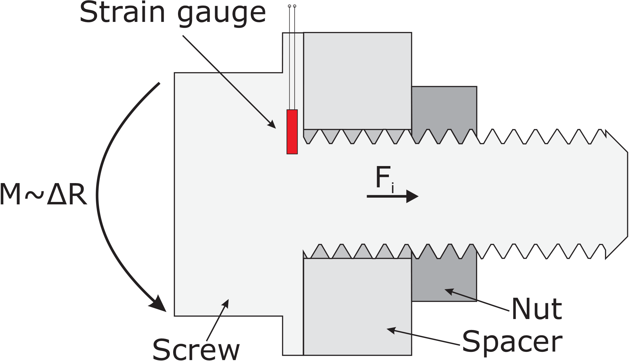
Figure 1Measurement concept of a “smart” screw, with a thin strain gauge integrated into a spacer disk between the head and shaft of a screw, where torsional moment M proportional to resistance change ΔR allows determination of the prestressing force Fi.
The preload force Fi of an ISO-standardized screw, which is a common indicator of the strength of a screw connection, can be estimated from the torsional moment M and the geometry of the screw as given in Eq. (1):
where d2 is the thread diameter, P is the thread lead, μt is the friction coefficient of the thread, μh is the friction coefficient of the screw head, and DKm is the effective diameter for frictional moment of the screw head (Decker et al., 2014).
Sensor positioning
The strain gauge must be integrated into the screw head in a position where significant strain occurs when fastening the screw. High circumferentially directed strain can be observed at the circumference of the shaft of a screw (Gere and Goodno, 2012). However, the placement of a strain gauge along the circumference is not reasonable, as the strain gauge would only be shifted along the circumference but not elongated. An elongation requires a gradient in spatial displacement as observed in the radial direction. In order to determine the optimal position, FEM simulations have been performed using COMSOL Multiphysics. Figure 2 shows qualitatively the radial strain distribution in the spacer disk 0.1 mm below the surface (left) and 0.5 mm below the surface (right). The maximum strain occurs at the circumference of the shaft. Close to the surface, the maximum is very narrow and sharply confined. The maximum strain lowers and the distribution widens deeper inside the material, so that strain is measurable in a larger area. Ideally, the strain gauge should be integrated at the circumference of the shaft slightly below the surface of the spacer disk.
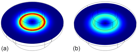
Figure 2Radial strain in the spacer disk of the screw head 0.1 mm below the surface (a) and 0.5 mm below the surface (b). The maximum strain is higher and the distribution more distinct towards the surface. Low strain is indicated by deep blue color and high strain by red color, respectively.
The fabrication process of the “smart” screw is divided into three major parts: preparation of the strain gauges, printing of the screw and integration of the sensor during the printing process. Following, a detailed description of all three steps is given.
3.1 Screen-printed strain gauge foil sensor
The design of the strain gauge is shown in Fig. 3 (left). Two strain gauges of a carbon-based ink are printed on a foil and connected by silver-printed tracks. The silver ink tracks have a resistance of approx. 18Ω and the carbon ink strain gauges of approx. 22 kΩ, respectively. Thus, the resistance of the tracks can be neglected. The width of the strain gauges and the electrical path is chosen to be 400 µm because we can reliably reproduce structures with those dimensions by manual screen-printing, whereas smaller dimensions are possible but more challenging to fabricate. The strain gauges can be connected in a Wheatstone bridge circuit as a half-bridge. When the screw is set under a torsional moment, the inner strain gauge is for temperature compensation, and it underlies almost zero strain because it is close to the neutral fiber of the screw. The outer strain gauge is set to tensile strain due to the torsional moment. Electrical tracks lead from the strain gauges to the contact pad area (see also Fig. 1), where they are connected with wires.
Functional printing is processed on a manual screen printing machine with a low-cost plastic screen from SEFAR (type PCF FC 180-27-Y-PW). The substrate is a 6 µm thick polyester foil (Mylar), which is stretched on a ceramic carrier. A relatively thin foil is necessary because the slice height of the 3-D printer is 25 µm (see the next section). In the first step, the electrical tracks are printed with the silver filled, stretchable conductor paste PE873 from DuPont. The structure is cured for 20 min at 120 ∘C in an oven. The film thickness after drying is around 5 µm. In the second step the carbon-based ink ECI 7004LR E&C from Henkel is applied. We have performed a detailed characterization of the strain sensitivity of the paste. The gauge factor is 3.02 ± 0.86 (Xu, 2017).
Afterwards the strain gauges are electrically connected at the contact pad area by a pin header and electrically conductive adhesive (Panancol Elecolit 3025, curing at room temperature for 24 h). The final foil sensor is shown in Fig. 3 (right).
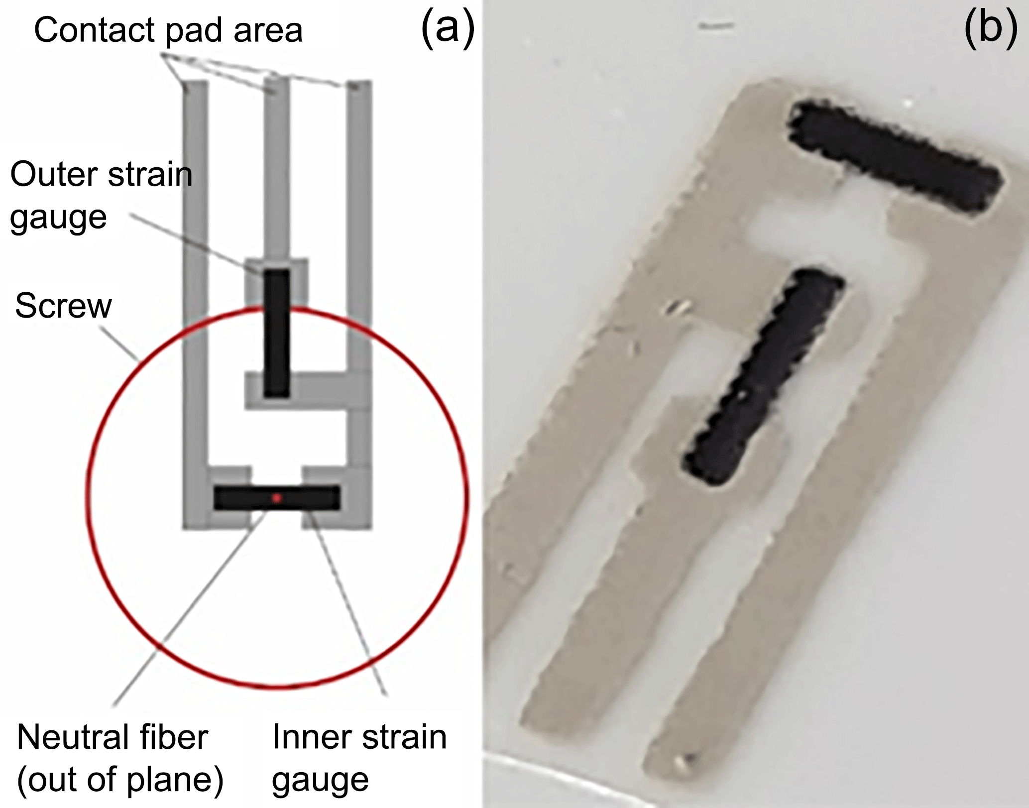
Figure 3Strain gauge layout relative to the screw shaft (a); screen-printed strain gauge on a 6 µm thick polyester foil (b).
3.2 3-D-printed screw
All parts are fabricated in an upright orientation using a microstereolithography printer (Perfactory Micro HiRes, EnvisionTec Inc., USA) at a slicing height of 25 µm. The slicing software used was Perfactory RP 3.0.900. No z and contour corrections have been applied. Four identical screws are printed in one run. We utilize two different acrylic resin materials. The first is a high-resolution, high-temperature, low-viscosity resin (HTM140 M, EnvisionTec Inc.) exposed for 3000 ms per slice, which results in a hard and brittle plastic with superior details and surface finish. The other is a considerably more viscous, sticky resin (ABS Flex, EnvisionTec Inc.), which results in a flexible, elastic plastic with a softer surface finish but fewer fine details. Here, we choose an exposure time of 800 ms per slice. The printing direction starts with the hex-head and washer disk placed on automatically generated supports.
As the proof-of-concept machine part, we have designed an ISO M6 screw with a hex-head and washer disk. The CAD model has been created in Autodesk Inventor. It consists of an M6 thread created by cutting a thread profile (60∘ flank angle, slightly enlarged from the ISO norm) into a 15 mm high screw shaft. A 1 mm thick, 15 mm wide spacer disk and a 5 mm thick hexagon block for a 10 mm screw wrench form the screw head. For sensor foil integration we placed opposing contact pad regions on top of the spacer. We also add alignment structures on one side for easier handling of the pin header, which is used for contacting. Finally, some labels are engraved on the top and bottom faces. The complete 3-D CAD model with a depiction of the integrated sensor foil is shown in Fig. 4.
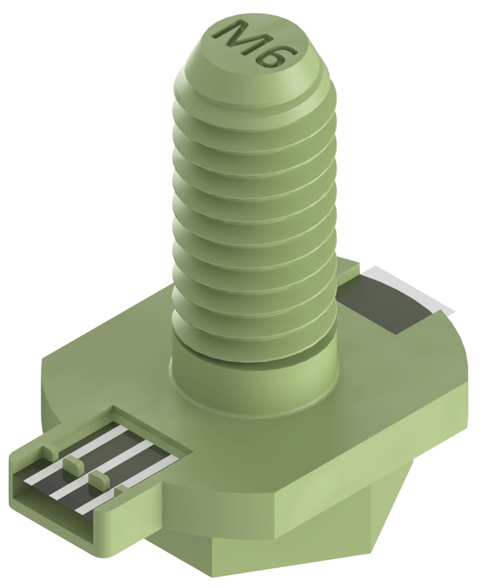
Figure 43-D CAD model of an M6 screw with hexagon head, spacer disk, and contact pad opening for sensor foil integration. The substrate foil and contact pads of the integrated sensor are visible.
To account for fabrication tolerances, as well as shrinkage after printing, the thread profile has to be slightly adjusted. This adjustment is highly dependent on the type of printing material, but also on processing and post-processing parameters such as exposure time and UV curing.
3.3 Sensor foil integration
For integration of the sensor foil element, we pause the print job after reaching a height of half the spacer disk (Fig. 5a). The printing platform is removed from the printer and the sensor foil is manually placed onto the washer disk, with the contact pads oriented upwards. The foil is centered and aligned according to the desired position of the resistors on the circumference of the screw shaft (Fig. 5b). Due to the strong adhesion of the thin foil to any surface and the liquid resin that remains on the screw heads, we stick sufficiently overhanging foil to the platform on both sides of the head and no further securing steps are necessary (Fig. 5c). The printing platform is then carefully realigned into its initial position and the printing process is resumed (Fig. 5d).
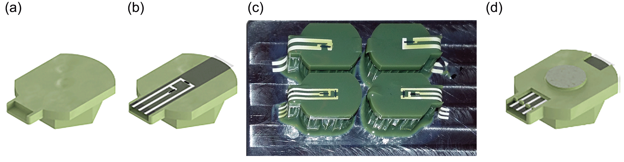
Figure 5Fabrication process: (a) printing of the screw head; (b) application and alignment of the strain gauge; (c) photography of printed screw heads with applied and aligned sensors continuation; (d) of the printing process. Liquid resin covers the screw heads during the integration and can be seen as a shiny film.
After printing, all parts are post-processed in a standard fashion, rinsing and cleaning with isopropanol, drying with compressed air, and post-curing in a flood UV bath for 2–5 min. Depending on the type of screen-printed ink that is exposed at the contact pads, compatibility with this process, such as chemical resistance to the liquid resins and isopropanol, stability during ultrasonic cleaning has been evaluated. Some post-processing steps such as ultrasonic cleaning can be adjusted or skipped.
Finally, each “smart screw” requires electric contacts to read out the strain gauge resistors. We connect pin headers through the printed alignment structures to the contact pads using electrically conductive glue. It is also advantageous to encapsulate the contact region with non-conductive glue or resin. If this region is opened towards the thread, the encapsulation should not extend beyond the washer thickness.
A photograph of the final screw is given in Fig. 6. The integrated foil sensor is visible through the half thickness of the spacer disk and issues of alignment are evident. Printed samples of both materials work well with metal and plastic nuts.
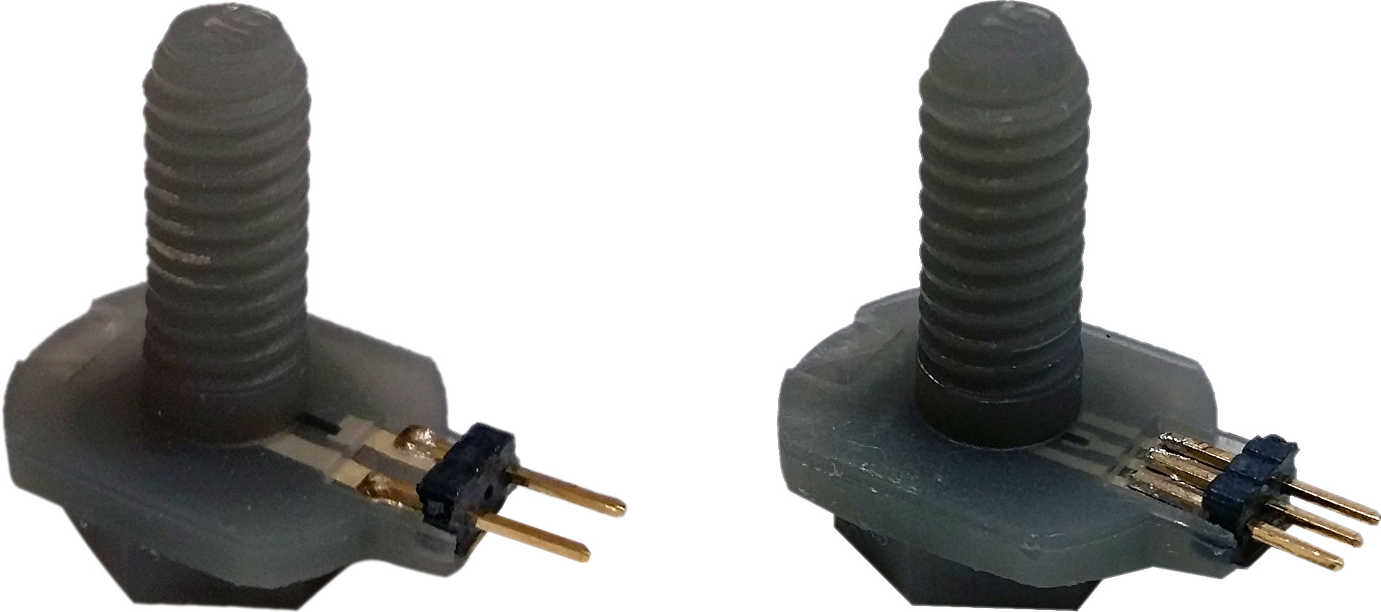
Figure 6Photograph of ABS Flex screws with an integrated sensor foil element; some misalignment of the sensor foil is evident on the left screw.
In preliminary work, we used a measurement setup in which the screw was fastened by a wrench that was moved by a way-driven XYZtec 2000 Multitester tool while the required force was recorded. The torque was calculated from the force and length of the lever. The main disadvantages of this setup were the missing compensation for angular movement of the wrench as well as the imprecise measurement of the length of the lever (Gräbner et al., 2017). Our optimized measurement setup especially addresses those issues and is shown in Fig. 7. A steel tube with an ISO M6 core thread on one end and a lever on the other is mounted in two PTFE bearings. The tube can rotate around its axis with only negligible friction between tube and bearings. The dynamic friction coefficient is approximately 0.04. The lever presses on a force sensor (TE Connectivity FS 20) when torque is applied to the tube. Thus, the tube is suspended from rotation and the calculation of the applied torque by multiplying the measured force by the length of the lever is possible.
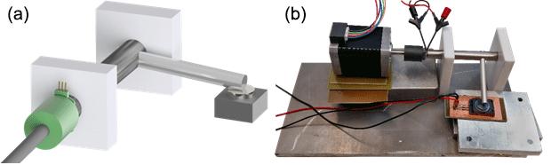
Figure 7Optimized measurement setup: (a) schematic depiction showing the steel tube, PTFE bearings, engine axis, nut and screw, lever and force sensor; (b) photography including the engine and connecting wires.
The resistance of the integrated strain gauge is recorded using a Keithley 2100 multimeter and the signal of the force sensor is recorded using a Keithley 2000 multimeter. The smart screw is fastened in the core thread using five-phase step engines (Orientalmotor PKP544MN18A and PKP546MN18A) with a very low angle resolution of 0.36∘/step and a maximum torque of 220 and 440 N mm, respectively. In order to verify that the measured torque is equal to the applied torque, a known torque is applied and compared to the measured torque. The difference in applied and measured torque is found to be negligible.
4.1 Mechanical characterization
For compatible combinations of inks, resin, and conductive glue, we have observed no or only negligible strain due to the integration process. While we expect a compressive load on the resistors, the low thickness of foil and film, as well as the layer-by-layer printing, does not lead to a noticeable change in the resistances. The foil is firmly embedded between the printed layers.
We performed die shear testing of the screws with and without integrated sensors to determine the influence of the foil on the mechanical properties of the screw. Figure 8 shows typical die shear test results for the two types of materials.

Figure 8Photographs of sheared-off screws: ABS Flex screw with integrated sensor (a), ABS Flex screw without integrated sensor (c), HTM140 M screw with integrated sensor (b), and HTM140 M screw without integrated sensor (d).
The hard and brittle HTM140 M screws with as well as without integrated foil typically shear off at the shaft, indicating no negative influence of the integrated sensor on the mechanical reliability. The more elastic ABS Flex screws shear off at the shaft as well, if there is no sensor integrated. The ABS Flex screws with integrated sensors sometimes shear off right above the foil, indicating that the mechanical durability of these screws may be deteriorated by an integrated sensor. The most likely reason for this influence is a poor adhesion between the ABS Flex material and the foil. Pausing, cleaning and resuming the printing process can also be another influencing factor.
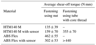
During shear testing, the torque necessary to shear off the screws was recorded and compared to previous results measured with another measurement setup; see also Gräbner et al. (2017). The results are shown in Table 1. The shear-off torque is significantly higher when the screw is fastened in a core thread that covers the whole thread of the screw, instead of a nut that only covers a portion of the thread of the screw. The shear-off torque of the HTM140 M screws was increased by 2.2×, whereas the standard deviation did not change. The ABS Flex screws could not be sheared off with the maximum torque of the engine of 440 N mm. Screws without a sensor have not been tested with the new setup.
Table 1Die shear test results for the different materials with and without an embedded sensor element.
4.2 Strain measurements
The electrical responses of the strain gauges in screws made from both materials are illustrated here. Figure 9 depicts the relative change in resistance versus the torque applied to the screw head. On the left, results of two screws made from ABS Flex and, on the right, results of two screws made from HTM140 M are shown.
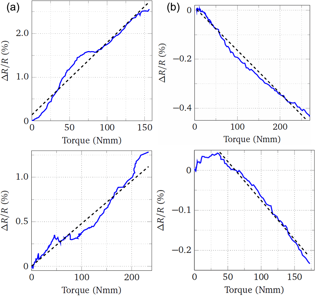
Figure 9Relative change in resistance versus torque applied to ABS Flex (a) and HTM140M (b) screws during the fastening phase.
The change in resistance is linearly related to the applied torque for both materials. For the ABS Flex screws, the resistance increases along with the torque as expected, indicating that the strain gauges are elongated. Surprisingly, the resistance of the strain gauges integrated into screws made from HTM140 M decreases with increasing torque, hence indicating a contraction or compression of the sensor. Previous results have shown a positive sensitivity for screws made from HTM140 M. The characterization has been performed with four screws per material. The average sensitivity for the ABS Flex screws is 11.4±6.68 and for the HTM140 M screws, respectively.
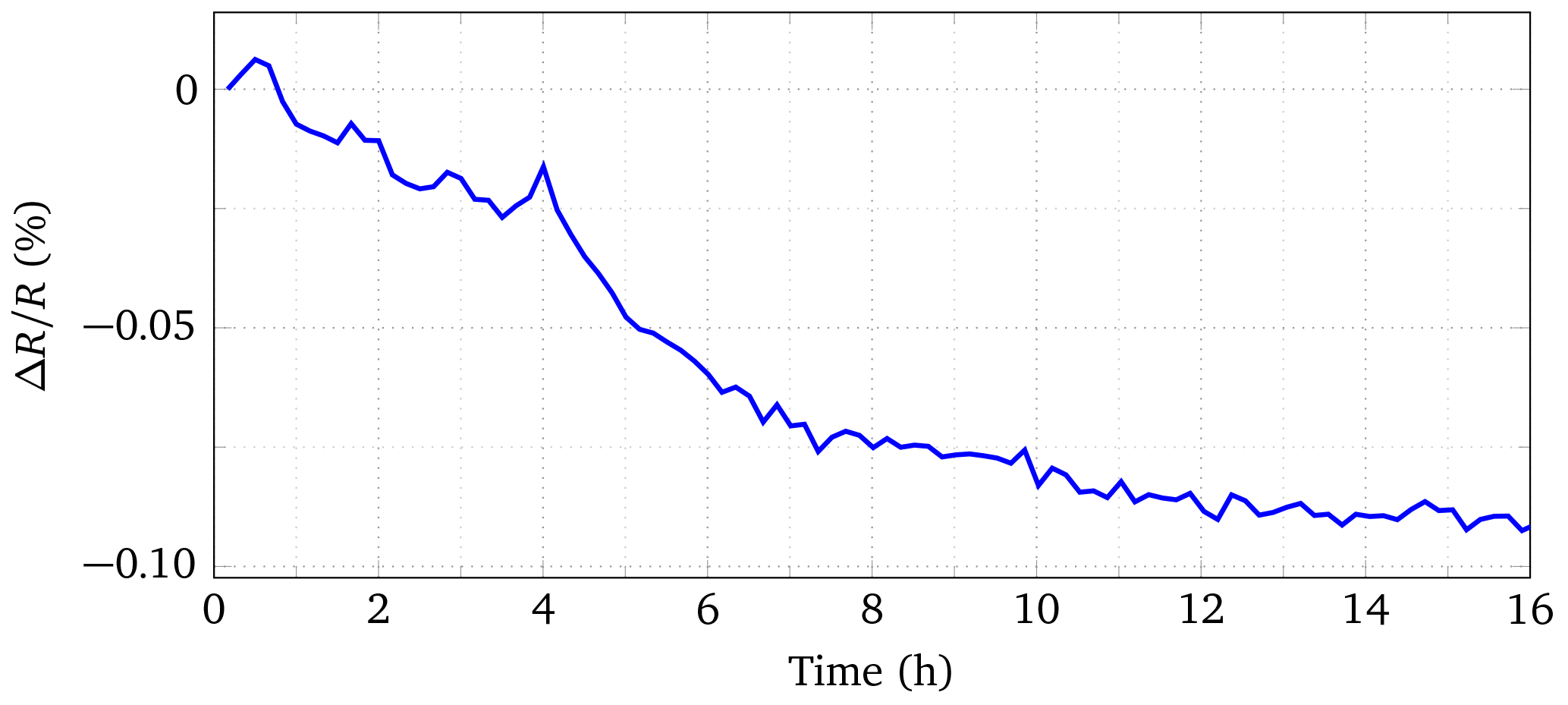
4.3 Material creep
Creep is a phenomenon that can be observed in many materials. Most polymers show extensive creep while under load. This behavior is caused by the structure of polymers. They usually consist of long molecule chains, which are entangled. When a load is applied, the chains tend to slide and the entanglements loosen over time, thereby causing high creep (Jansen, 2015). Such creep phenomena can also be observed after fastening a polymer screw. Figure 10 shows the change in resistance of the strain gauges over a time of 16 h after the screw has been fastened for an ABS Flex screw. In the first 8 to 10 h after fastening the strain gauges, resistance decreases quickly. Then the change slows down and follows an almost linear trend.
4.4 Preload force
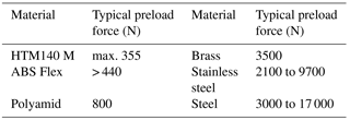
Following Eq. (1), the preload force Fi of the screw can be correlated with the change in resistance using the measured torque and the known dimensions of the screw, which are P= 1 mm, d2= 5.53 mm, α= 60∘, DKm= 10 mm and 0.1. The result is kN for the ABS Flex screws and, respectively, kN for the HTM140 M screws. Table 2 gives an overview of typical preload forces for ISO M6 screws made from different materials and the values we calculated for HTM140 M and ABS Flex. The maximum preload forces HTM140 M can sustain are significantly below the value a common Polyamid screw can withstand. The maximum preload force of the ABS Flex screws could not be determined because the step engine was not able to shear off the screw.
Table 2Typical preload forces for ISO M6 screws made from different materials (Reyher, 2010).
As a result, from the measurement we can observe a difference in the sensor response in dependency on the screw material. This is not expected, but multiple sources might be the cause of it. A possible reason is a difference in adhesion from the 3-D-printed polymers to the sensor foil, leading to a difference in strain transfer from the screw to the sensor. We observed that the HTM140 M material has better adhesion to the foil than the ABS Flex material by curing the resins on the foil and performing a peel test. HTM140 M could not be peeled off the foil after curing, whereas ABS Flex could be peeled off. A difference in strain transfer might very well be the reason for the difference in sign of the measurement results.
Another reason could be the misalignment of the sensor inside the screw. Figure 11 shows a HTM140 M screw that has been sheared off at the position of the integrated sensor. The sensor is partially sticking to the shaft and it can clearly be seen that the strain sensing resistor is not located at the boundary of the shaft. This misalignment is either caused by a faulty integration or by movement of the sensor between alignment and continuation of the printing process. As the printed screw heads are still covered with liquid resin material when the sensor is aligned, it is very possible that the sensor floated slightly when the printing platform was reinserted in the printer. At the center of the shaft, a non-negligible strain in the shaft direction occurs. This is caused by the preload force Fi and interferes with the radial strain, thus causing a negative sensitivity. Only close to the screw shaft circumference is the radial strain higher than the strain caused by the preload force and, hence, the influence of the preload force is negligible.
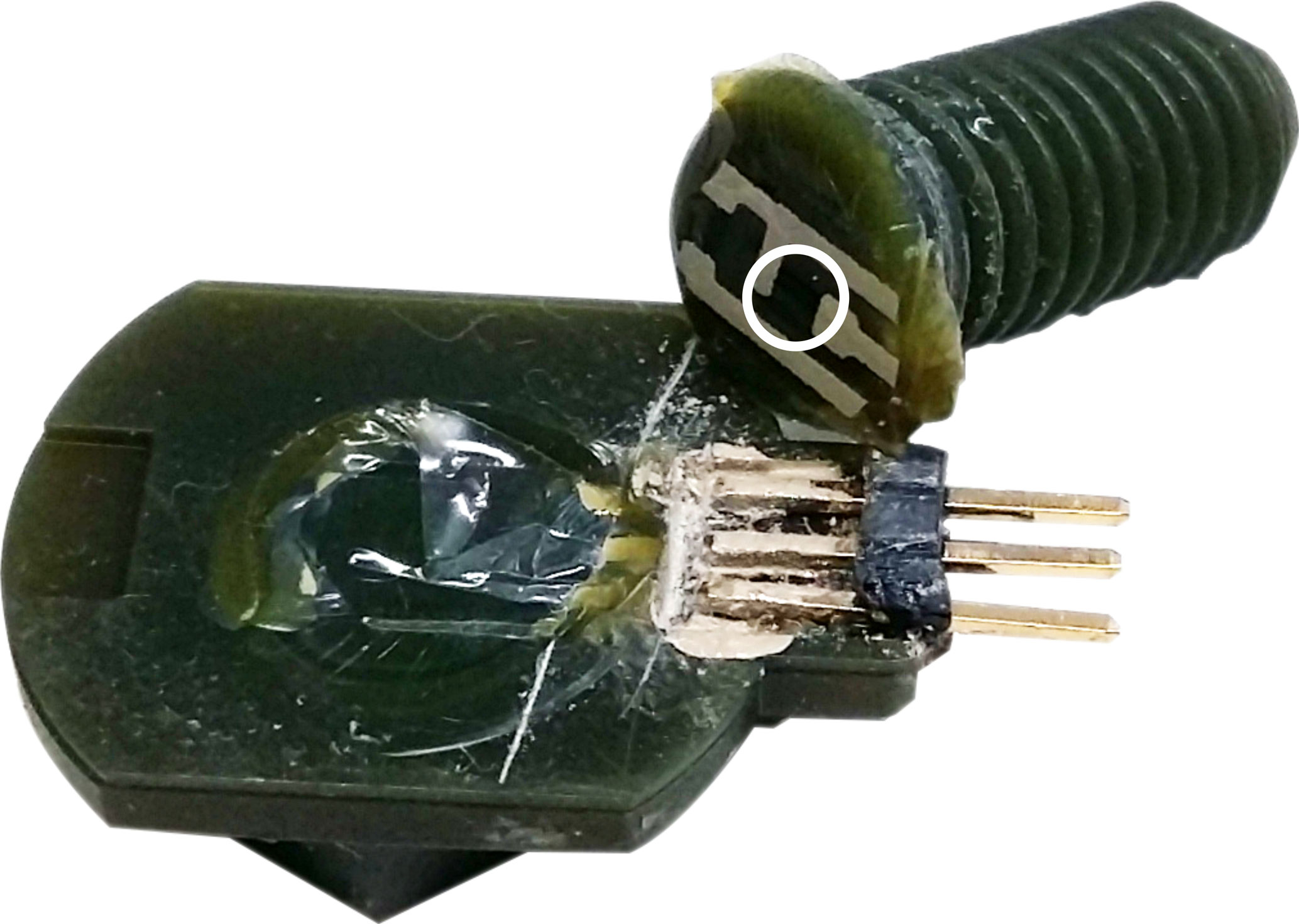
Figure 11HTM140 M screw sheared off at the position of the sensor. The strain sensing resistor is marked with a white circle.
The third reason that could cause the difference in sign is intrinsic stress that is induced into the screws during printing and curing. If the screws are prestressed, this prestress might also cause a prestrain of the sensor, which would be reduced when fastening the screw. This might explain the decrease in resistance when fastening the screw. When comparing the sensors' resistance before and after integration, we observed a small change in resistance. However, it could not be determined whether this change is caused by strain or by a modification of the sensing material due to exposure to UV light, contact with the resin chemicals or temperature influence.
In addition to the difference in sign, a difference in sensitivity has also been observed. This difference is explained by the different material properties of ABS Flex and HTM140 M. Under the same load, ABS Flex will show more deformation than HTM140 M, as the ABS Flex material is much softer than HTM140 M. The higher deformation leads to much higher strain being transferred to the strain gauge, thus causing the difference in sensitivity.
The difference in shear-off behavior between the two materials can be explained by the difference in adhesion between the 3-D-printed material and the sensor foil. HTM140 M screws typically shear off at the shaft, whereas ABS Flex screws mostly shear off at the sensor foil. As the adhesion of HTM140 M to the foil is much better, the sensor is better integrated into the screw and causes a negligible foreign body effect. The comparably poor adhesion between ABS Flex and the sensor foil causes the foil to be a large foreign body inside the screw and to act as a material defect. Thus, the mechanical stability of the screw is reduced at the integration area.
The required shear-off torque measured with the improved measurement setup is much higher than with the previous setup. In the improved setup, that screw was fastened in a core thread, whereas in the old setup the screws were fastened in a nut. Apparently, the core thread leads to a higher mechanical stability of the screws. This might be caused by better stress distribution on the thread leads as all leads of the screw have mechanical contact with leads of a core thread, whereas only a few leads have mechanical contact with leads of a nut.
After fastening an ABS Flex screw, we observed a decrease in resistance of the strain gauge over time. Creep of the polymer materials most likely causes this change. While the material is under load, the internal stress slowly reduces, causing a reduction of the strain that is transferred to the strain gauge. However, a long-term drift of the resistance of the printed strain gauges could also explain the decrease.
The preload forces we have calculated line up well with the typical preload forces for commercially available screws. Due to the layer-wise 3-D printing fabrication of the presented screws we expected the mechanical stability to be inferior to the stability of other screws. In the case of the HTM140 M material our assumption was right. However, ABS Flex screws might be able to withstand a similar preload force to Polyamid screws. Metal screws can obviously withstand much higher preload forces.
We have presented the concept of “smart” additively manufactured parts by combining different materials and technologies. As proof of concept, we reported the extended characterization of a 3-D-printed screw with an integrated resistive strain gauge made by functional screen printing. In this example, the layer-by-layer 3-D printing process was paused, the strain gauge foil sensor embedded onto the current layer, and printing resumed. The screws were manufactured from two different materials: HTM140 M, which is hard and brittle, and ABS Flex, which is more flexible. The influence of the integrated sensor on the mechanical behavior has been evaluated by die shear testing. Fastening the screw in a core thread, which covers the whole thread of the screw, leads to a significantly higher shear-off torque than fastening the screws using a nut, which only covers a part of the thread of the screw.
A measurement setup has been developed that allows the characterization of the sensors' response during the complete fastening of the screw. The torque applied to the screw head correlates linearly with the change in resistance of the integrated strain gauge with an average sensitivity of 11.4 ± 6.68 for the ABS Flex screws and for the HTM140 M screws, respectively. The negative sensitivity of the HTM140 M screws contradicts previous results and is most likely caused by misalignment of the sensor during the integration. Hence, a very precise alignment of the sensor is necessary to ensure the desired functionality. Possible solutions to avoid misalignment and floating of the sensor before it is fixed by surrounding material are the introduction of alignment marks on the sensor foil, suitable clamping structures printed next to the screw and disposed of after the fabrication, as well as use of thicker, heavier foil substrates and corresponding minimal cavities on the integration layer.
A correlation between the change in resistance of the sensor and the preload force Fi of the screw has been established and allows the calculation of Fi from the measured resistance. The preload force is the most common indicator of the strength of screw connections.
In future work, the alignment issues must be addressed. The idea of the integration of sensors into 3-D-printed parts during additive fabrication can also be transferred to parts other than screws, such as nuts, springs, or clamps, other printing materials, such as metals or ceramics, and printing methods, such as selective laser melting or selective laser sintering.
The data are stored internally according to the requirements of our quality management system and can be accessed upon request.
GD and FL developed the concept for the smart screw and acted as scientific advisors. DG and SD fabricated the screws, developed the measurement setup and performed the measurements. DG and FL wrote the manuscript.
The authors declare that they have no conflict of interest.
This article is part of the special issue “Sensor/IRS2 2017”. It is a result of the AMA Conferences, Nuremberg, Germany, 30 May–1 June 2017.
The authors thank Ingrid Michels for assistance with electrical contacting
of printed sensor foils as well as Walter Lang and Michael Vellekoop for
their scientific advice and guidance. The authors also acknowledge the
University of Bremen for funding the postdoctoral research project
“AddSense: Additive manufacturing for local fabrication of sensor
structures for material integrated sensing”.
Edited by: Juergen Wilde
Reviewed by: two anonymous referees
Chang, C.-C., Liu, C.-Y., Huang, K.-H., and Feng, G.-H.: Design of Wireless Sensors for Intelligent Manufacture Monitoring, International Journal of Automation and Smart Technology, 4, 168–173, https://doi.org/10.5875/ausmt.v4i3.604, 2014.
CiS Forschungsinstitut für Mikrosensorik GmbH: Safety First – Measurement of pre-tensioning forces in screw connections, Press release 01/2017, Erfurt, Germany, 2017.
Decker, K.-H., Rieg, F., Weidermann, F., Engelken, G., and Hackenschmidt, R.: Decker Maschinenelemente, 19th Edn., München, Carl Hanser Verlag, 2014.
Delamare, J., Sanders, R., and Krijnen, G.: 3-D printed biomimetic whisker-based sensor with co-planar capacitive sensing, https://doi.org/10.1109/ICSENS.2016.7808631, IEEE. Sens. J., 2016.
Dumstorff, G. and Lang, W.: Printed Sensors for Material Integrated Sensing: Functionalization of Semi-Finished Parts, Proc. Eurosensors, Paris, France, September, https://doi.org/10.3390/proceedings1040608, 2017.
Dumstorff, G., Paul, S., and Lang, W.: Integration Without Disruption: The Basic Challenge of Sensor Integration, IEEE Sens. J., 14, 2102–2011, https://doi.org/10.1109/JSEN.2013.2294626, 2014.
Espalin, D., Muse, D. W., MacDonald, E., and Wicker, R. B.: 3-D Printing multifunctionality: structures with electronics, Int. J. Adv. Manuf. Tech., 72, 963–978, https://doi.org/10.1007/s00170-014-5717-7, 2014.
Gere, J. M. and Goodno, B. J.: Mechanics of Materials, 8th Edn., Stamford: Cengage Learning, 2012.
Gräbner, D., Dumstorff, G., and Lucklum, F.: 3-D Printed Machine Parts: Functionalization During Additive Fabrication, Proc. Sensor, 2017, Nürnberg, Germany, May, https://doi.org/10.5162/sensor2017/D1.4, 2017.
Hautamaki, C., Zurn, S., Mantell, S. C., and Polla, D. L.: Experimental evaluation of mems strain sensors embedded in composites, J. Microelectromech. S., 8, 272–279, https://doi.org/10.1109/84.788631, 1999.
Ibragimov, A., Pleteit, H., Pille, C., and Lang, W.: A Thermoelectric Energy Harvester Directly Embedded Into Casted Aluminum, IEEE Electr. Device L., 33, 233–235, https://doi.org/10.1109/LED.2011.2174605, 2012.
Jansen, J.: Understanding creep failure of plastics, Plastics Engineering, July/August, 2015.
Klassen, A., Rübner, M., Ilg, J., Rupitsch S. J., Lerch, R., Singer, R. F., and Körner, C.: Influence of the fabrication process on the functionality of piezoceramic patch Transducers embedded in aluminum die castings, Smart Mater. Struct., 21, https://doi.org/10.1088/0964-1726/21/11/115014, 2012.
Lee, K., Lee, S. S., Lee, J. A, Lee, K.-C., and Ji, S.: Carbon nanotube film piezoresistors embedded in polymer membranes, Appl. Phys. Lett., 96, 013511, https://doi.org/10.1063/1.3272686, 2010.
Lehmhus, D., Aumund-Kopp, C., Petzoldt, F., Godlinski, D., Haberkorn, A., Zöllmer, V., and Busse, M.: Customized Smartness: A Survey on Links between Additive Manufacturing and Sensor Integration, Proc. Tech., 26, 284–301, https://doi.org/10.1016/j.protcy.2016.08.038, 2016.
Leigh, S. J.: Polymer composites for 3-D printing of functional sensors and transducers, IEEE Sens. J., https://doi.org/10.1109/ICSENS.2016.7808629, 2016.
Lucklum, F. and Dumstorff, G.: 3-D Printed Pressure Sensor with Screen-Printed Resistive Read-Out, Proc. IEEE Sensors 2016, Orlando, FL, October, https://doi.org/10.1109/ICSENS.2016.7808633, 2016.
Martínez, I. and Andrade, C.: Examples of reinforcement corrosion monitoring by embedded sensors in concrete structures, Cement Concrete Comp., 31, 545–554, https://doi.org/10.1016/j.cemconcomp.2009.05.007, 2009.
Qin, L. and Li, Z.: Monitoring of cement hydration using embedded piezoelectric transducers, Smart Mater. Struct., 17, https://doi.org/10.1088/0964-1726/17/5/055005, 2008.
Reyher Nchfg. GmbH & Co. KG: Montage von Schraubverbindungen, Product Catalogue 2010, 177–183, 2010.
Salas, M., Focke, O., Herrmann, A. S., and Lang, W.: Wireless power transmission for structural health monitoring of fiber-reinforced-composite materials, IEEE Sens. J., 14, 2171–2176, https://doi.org/10.1109/JSEN.2014.2305578, 2014.
Vaezi, M., Seitz, H., and Yang, S.: A review on 3-D micro-additive manufacturing technologies, Int. J. Adv. Manuf. Tech. 67, 1721–1754, https://doi.org/10.1007/s00170-012-4605-2, 2013.
Woo, S.-J., Kong, J.-H., Kim, D.-G., and Kim, J.-M.: A thin all-elastomeric capacitive pressure sensor array based on micro-contact printed elastic conductors, J. Mater. Chem. C, 2, 4415–4422, https://doi.org/10.1039/C4TC00392F, 2014.
Wu, S.-Y., Lin, C.-C., Lin, D.-Y., Chen, A.-L., Chuang, C.-S., Huang, W.-C., and Liu, S.-H.: 3-D Printed “Smart Screw” with Build-in LC Sensing Circuit for Wireless Monitoring, Proc. Transducers 2017, Kaohsiung, Taiwan, https://doi.org/10.1109/TRANSDUCERS.2017.7994201, 2017.
Xu, M.: Fabrication and Characterization of Screen-Printed Strain Gauges on Steel Substrates, Bachelor Thesis, University of Bremen, 2017.