the Creative Commons Attribution 4.0 License.
the Creative Commons Attribution 4.0 License.
 | 19 Apr 2018
Autonomous micro-platform for multisensors with an advanced power management unit (PMU)
Pierre Bellier
Philippe Laurent
Serguei Stoukatch
François Dupont
Laura Joris
Michael Kraft
In this work, we developed and characterised an autonomous micro-platform including several types of sensors, an advanced power management unit (PMU) and radio frequency (RF) transmission capabilities. Autonomy requires integration of an energy harvester, an energy storage device, a PMU, ultra-low-power components (including sensors) and optimized software. Our choice was to use commercial off-the-shelf components with low-power consumption, low cost and compactness as selection criteria. For the multi-purpose micro-platform, we choose to include the most common sensors (such as temperature, humidity, luminosity, acceleration, etc.) and to integrate them in one miniaturised autonomous device.
A processing unit is embedded in the system. It allows for data acquisition from each sensor individually, simple data processing, and storing and/or wireless data transmission. Such a system can be used as stand-alone, with an internal storage in a non-volatile memory, or as a node in a wireless network, with bi-directional communication with a hub device where data can be analysed further. According to specific application requirements, system settings can be adjusted, such as the sampling rate, the resolution and the processing of the sensor data.
Parallel to full autonomous functionality, the low-power design enables us to power the system by a small battery leading to a high degree of autonomy at a high sampling rate. Therefore, we also developed an alternative battery-powered version of the micro-platform that increases the range of applications. As such, the system is highly versatile and due to its reduced dimensions, it can be used nearly everywhere. Typical applications include the Internet of Things, Industry 4.0, home automation and building structural health monitoring.
- Article
(494 KB) - Full-text XML
- BibTeX
- EndNote


With the emergence of the Internet of Things (IoT) and the trend for miniaturisation to make every object smarter and smaller, the need of sensors is growing faster and faster. Experts predict that the installed number of IoT sensors will reach more than 20 billion units for 2020, which represents a market of more than USD 2.9 trillion (Middleton, 2017; Bauer et al., 2014; Manyika et al., 2015; Montgomery, 2017). If all these connected devices are powered in a conventional way, the costs and the ecological impact caused by battery usage will be a major concern. Firstly, because the energy required to manufacture batteries is 50 to 150 times higher than what it releases during its use (Kengen, 2009). Secondly, because a non-negligible amount of batteries is not recycled correctly (about 30 % in Switzerland according to FOEN, 2016) and that toxic materials are then eventually released into the environment.
It is therefore a major challenge to evolve smart devices to operate without batteries or drastically limit their use of batteries. This provided the motivation for our development to realise an ultra-low-power and compact multi-sensor platform leading to partial or full autonomy.
The design was driven by two main application areas: Industry 4.0 and home automation. The objectives and specifications are different: for industry, precise monitoring of machines is an important objective, whereas for home automation we want to collect data, for example, to optimise the overall energy consumption or the wellbeing of people (heating, cooling, air quality). The common characteristic of both application areas is to minimise the operational and maintenance costs of the sensor system. Indeed, nowadays, no one wants to allocate resources and time to change batteries that are often housed in difficult to access places.
We chose to develop two platforms: the first can harvest energy from the environment and the second embeds a small battery to power the system. Both platforms are wireless as a wired connection often cannot be realised on rotating machines or in closed spaces, or installation increases the costs drastically. There is an increasing demand for wireless autonomous sensor platforms in which there is no need for wires to power the system and to retrieve the data. In the following we will discuss in detail two types of platforms, what we call the autonomous platform and the battery-powered platform.
There is considerable interest and effort in the field of very-low-power and autonomous monitoring systems. In this section we compare some of the previous research results to the work described in this paper.
The Holst Center at Eindhoven developed a wireless microsystem dedicated to low range pressure measurement powered by an electrostatic energy harvester. It is consuming 3.5 µW to send a pressure measurement every minute (Elfrink et al., 2015).
EnOcean ECO 200 and PTM330 (2017) home automation devices require an energy pulse of 120 µJ, that can be harvested by actuating a switch, to send three radio telegrams containing a unique 32-bit module ID, the polarity of the energy pulse and the operating status of 4 digital inputs using a proprietary protocol.
Texas Instruments proposes its SensorTag (2017), a kit that can comprise up to 10 low-power MEMS sensors communicating through Bluetooth Low Energy, 6LoWPAN or ZigBee protocols. According to the commercial specification, it can send data at a rate of 1 Hz for 1 year using a CR2032 coin cell battery as a power source. It corresponds to a power consumption of 69 µW that we could not reproduce in testing.
Torfs et al. (2013) propose a wireless sensor network for monitoring the structural health of buildings, with special focus on assessing earthquake-related damages. A network of strain sensors and accelerometers measures periodically the structural-health-related parameters and transmits the obtained data over a 900 MHz wireless link. To power each node in the network, they use relatively large C-cell batteries of 8.5 Ah capacity. The nodes have a power consumption of 274 µW for the strain sensors (data sent every minute) and 1.73 mW for the 200 Hz accelerometers (15 s polling interval).
Torah et al. (2008) describe an autonomous wireless sensor node, using vibration energy harvesting for sensing the wear of bearings through vibration monitoring. A supercapacitor is used to store energy of vibration and to power the microcontroller, the radio frequency (RF) transmitter and the sensor (a 3-axis accelerometer). The power consumption achieved was 21.3 µW for taking 16 measurements at a sampling rate of 1250 Hz and transmitting the peak value (17 bits) on a 433 MHz RF link every 3.28 s.
Yue et al. (2017) described an indoor low lighting (200 lux) photovoltaic energy harvesting block that is combined in a power management unit (PMU) with a commercial battery charger and a supercapacitor. They used it with a solar panel of 25 cm2 to power a CO2 concentration level sensor. They achieved a power consumption of the PMU alone of 10 µW (which is dominated by the supercapacitor leakage).
A comparative table of wireless microsystems is given in Table 1. Overall comparison is difficult because of the diversity of systems described and the fact that details about the wireless communication are not always available; power consumption of wireless devices is strongly related to the power of transmission and the protocol used.
Table 1Comparison of wireless microsystems discussed. n/a – not applicable.
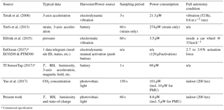
* Commercial specification
As can be seen from the above-mentioned previous work, the most important trend for wireless sensor platforms is to reduce power consumption in order to make them fully autonomous based on energy harvesting or at least to extend the autonomy of the battery used to power them. The micro-platform we developed combines all the advantages of the aforementioned systems: (1) it is versatile due to the large amount of sensors it integrates, (2) it can operate for a long period at high sampling rate on battery due to specific low-power electronic component selection and smart embedded-software development, (3) it is able to operate in a fully autonomous mode when equipped with a photovoltaic panel as energy harvester while keeping its dimensions reduced and (4) it requires little or no maintenance. We achieved a power consumption of 8.8 µW to send the data from four sensors every minute, which can lead to 425 days of operation on a CR2016 battery. The system can also be fully autonomous with a solar panel of 23.9 cm2 under low lighting conditions of 200 lux. Furthermore, when the supercapacitor is fully charged, it can operate for 92 h in the dark.
As explained in the introduction, we focused on two platforms: one autonomous platform and one battery-powered platform.
The battery-powered platform is mainly designed for industrial automation. We used the following technical specifications that are generally required by industry: a system operates typically in a harsh environment, a system requires a combination of dynamic and quasi-static sensors, a system must process and store a large amount of data, it must have high autonomy, and the antenna must have a standard range of a few tens of metres.
The harsh environments encountered in industry was defined by high or low temperatures that the system can be exposed to (−30 to 85 ∘C), mechanical shocks and vibrations, contaminations of different natures and impact on the system in the form of dust and fluids, etc.
The sensors onboard our system are intended to monitor several essential parameters that directly or indirectly give information on the operating conditions of the machine it is placed on. For example, the temperature increase above a certain value or excessive vibration can indicate on dysfunction. The system is supposed to detect such parameter variation and send a corresponding signal to the maintenance team before a catastrophic failure or a major defect occurs.
Before the use of sensors, in the worst-case scenario, an operator was estimating the temperature or listening to the noise emitted by the rotating part to perform his subjective assessment if there is a problem. With a wireless sensor micro-platform, the monitoring can be automated and unbiased by excluding or at least drastically reducing the impact of the human factor.
We classified sensors into two main categories. Quasi-static sensors are related to physical quantities that vary slowly (time constant > 1 s) such as temperature or humidity. In contrast, dynamic sensors are related to dynamic parameters such as shocks and vibration. The dynamic sensors require a high sampling rate, typically hundreds of hertz, and thus generate a large volume of data. The data can be processed by the system, stored in the system memory and/or sent to the processing station. Such operations are time and energy consuming. Although, for industry, energy is not a main concern, a battery can power the system as long as the autonomy is sufficient (typically more than 1 year). In some cases, the system can be easily powered by the electrical grid.
The autonomous platform has been designed especially for home automation with a focus on energy saving, wellbeing, health and comfort monitoring. The platform must meet specifications that are typically different from the industrial model. First of all, the system operates in a standard environment (−20 to 60 ∘C, no or very little vibration, no contamination by liquids). It must host quasi-static sensors; that is why there is not a real demand for large volume data storage. The need to replace a battery, at least often, is undesirable. As a result, the system must have an extended autonomy or, in an ideal case, be fully autonomous. As buildings become larger, the antenna must have a long range in indoor conditions (more than 20 m). For standard domestic housing, the signal must be collected from every room, despite the walls and floors attenuation.
The typical physical parameters that fall in the quasi-static category are temperature, humidity, luminosity, etc. The system must be fully autonomous within a specified lifetime (at least 3 years) and the autonomy can be achieved in an ideal case by using solar cells. The system must be able to operate without interruption when lighted at least 8 h a day (minimum 200 lux) with a maximum continuous dark (0 lux) period of 48 h every week, corresponding to the weekend.
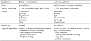
In Table 2, the most typical features for battery-powered and autonomous platforms are summarised and compared.
Table 2Summary of specifications for the battery-powered and the autonomous platforms. Optional sensors are listed in brackets.

The autonomous platform comprises three main blocks as presented on Fig. 1: the sensor block, the power block and the functional block. The sensor block contains all the sensing devices together with their conditioning electronics (amplifiers, filters, etc.). The power block comprises an optimized PMU, a battery (in case of a battery-powered platform) or an energy harvesting system that converts energy available in the surrounding environment of the device into electrical energy. The third block is the functional block consisting of the microcontroller unit (MCU), the RF module and/or the data storage front end.
It is important to note that battery-powered and autonomous platforms share a common design. An ultra-low-power MCU with integrated 2.4 GHz transceiver that constitutes the core of the microsystem. The MCU is in charge of reading the sensor outputs, formatting the data according to our proprietary protocol and sending the data via the RF link or to store them in a mass storage memory. In some prototypes, as an optional feature, we designed a data storage that we realised by using a standard micro-SD card.
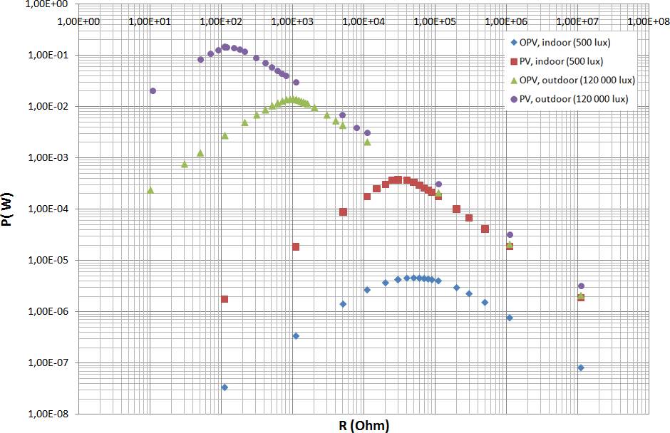
Figure 2Comparison of the power (P in Watts) harvested between photovoltaic (PV) and organic photovoltaic (OPV) in in/outdoor standard conditions. The curves have been normalised to the surface of the two cells.
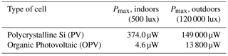
Table 3Maximum power (µW) harvested by the PV and OPV under different illumination conditions.
In order to have a compact device, the antenna is patterned directly on a FR4 substrate (glass-reinforced epoxy laminate material) with a 18 µm thick copper layer. It is a meandered inverted-F antenna occupying a surface area of about 0.9 cm2. The sensing part comprises several off-the-shelf sensors: a compact 3-axes accelerometer, a temperature sensor, a humidity sensor and a light sensor. Any additional sensor can be connected with the MCU using either an analog port or a common digital bus (such as SPI, I2C, etc.). Any modern ultra-low-power sensors can potentially be used as their power consumption is not significant as compared to the microcontroller and especially the RF transmission power. The sensors integrated into our prototypes typically have a readout time below 10 ms and consume less than 0.5 mA in operation. This is to be compared with low-power microcontrollers that consume between 0.5 and 5 mA in operation (according to the operating frequency), and the RF transmission consumption which is typically between 10 and 15 mA for 5 to 10 ms (according to the data size). Additional to the selection of ultra-low-power sensors, the embedded software is programmed to use as little energy as possible by enabling low-power standby modes and shutting down unused modules.
Besides the sensing part, the battery-powered platform differs from the autonomous version by having a different power source. The power source includes a coin cell CR2016 (3 V, D=20 mm, t=1.6 mm) that is combined with a specific electronic circuit to sustain short current peaks (> 10 mA).
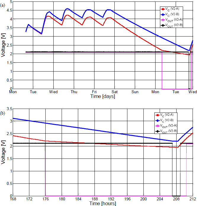
Figure 3(a) Evolution of the voltage at the supercapacitor (VC) subjected to charging from 8 h light during 5 days followed by a full dark period until insufficient voltage to operate. The cold start is observed after being lighted again. (b) Zoom on the last hours of the measurements when not enough energy is available to get VOUT=2.1 V at the voltage regulator output. V2-A and V2-B refer to the standard PMU and enhanced PMU, respectively.
For the autonomous platform, we primarily used an amorphous silicon solar panel coupled with a tailored PMU for energy harvesting and a supercapacitor to store energy for powering the device when not enough light is available for direct powering. Solar panels are mainly designed for outdoor lighting, thus, due to the poor spectrum and light levels indoors (typically 300–500 lux), the surface area of the chosen solar cell was somewhat oversized to operate both inside and outside.
Depending on the application that often defines the operational environment, there might be different external sources of energy available apart from light; the most common are vibration, heat flux and ubiquitous RF electromagnetic waves. Such sources are potentially suitable and can be utilised to harvest energy in an applicable form.
Often the problem is that, for our intended applications, we do not always have sufficient levels of vibration, heat flux or RF emission that can be harvested and transformed into the amount of energy needed to power our system, whereas light is present most of the time and offers a fair energy density (1–10 W m−2 for indoor artificial lighting, up to 1000 W m−2 in full sun; Randall and Jacot, 2002). Therefore, we selected light as the main source of energy to power our autonomous system. The light is to be harvested and converted into an applicable form using solar cells.
There are several types of photovoltaic (PV) elements, the most common among them being monocrystalline and polycrystalline silicon, thin-film and organic PV (OPV; El Chaar et al., 2011; Gul et al., 2016). Not all of them are commercially available, while other ones are too expensive for our envisaged applications. There is another important factor to select a suitable PV element: the requirement for compactness of the system. The size of the energy harvester should be adapted from the balance between the energy required to power the system and the energy density existing in the ambient environment, in our specific case light intensity.
We compared two types of PVs: polycrystalline silicon and organic photovoltaic (OPV). The polycrystalline PV was a commercially available outdoor solar panel of 23.9 cm2. The OPV has been synthesised by our project partner Materia Nova (innovative materials research and development centre; MateriaNova, 2017).
As shown in Fig. 2, we plotted the characteristics of the PV and OPV. We compare both kinds of solar cells by measuring the power delivered to a resistive load (Laurent et al., 2013).
In Table 3, we presented the maximum power that can be harvested using the PV and OPV at two different conditions: indoors and outdoors.
Table 4Comparison of the power consumption (µW) of the platform with different sampling frequencies.
Despite recent progress in efficiency for OPVs, we cannot harvest enough energy in low lighting (500 lux) indoor conditions to power our system that needs at least 10 µW to send the sensor values every minute. For an outdoor usage (120 000 lux) the OPV can be sufficient although is not very resistant.
As a conclusion, we have decided to use PV cells in order to harvest enough energy to power the system indoors. Additionally, the PV cells have several advantages: it is a well-established technology with a combination of high cell efficiency and low cost (Kazmerski, 2012). Important to remember is that the output power of the PV cell can vary over 3 orders of magnitude from indoor to outdoor light because of the different spectrum and higher luminous flux.
5.1 Power management unit
The energy harvester is connected to the first stage of the PMU. It consists of a specific electronic circuit emulating a diode that would have a very low voltage drop. Indeed, when no input power is available, the energy harvester can be seen as a load, leading to a current leakage. For this reason, a diode is required between the solar cell and the PMU. A conventional passive diode will induce a voltage drop (forward bias) of 0.7 V typically while having an extremely low reverse current. In order to reduce the forward bias, hence increasing the efficiency of the device, we designed an active diode, based on ultra-low-power integrated circuits, that allows for lowering the forward bias down from 0.7 V to only 0.02 V, while consuming less than 1 µA. Models V2-A and V2-B refer to the standard PMU and enhanced PMU, respectively. Both platforms are put in the same conditions and subjected to a lighting level of 300 lux. The results of the comparison are depicted in Fig. 3 where a 50 % increase in the autonomy is obtained for V2-B.
A tailored ultra-low-power limiter prevents the voltage to go above a defined threshold to protect the supercapacitor.
The platform was designed to work in very poor lighting conditions: 200 lux, 8 out of 24 h and 5 days a week. The rest of the time the system can be in the dark. A value of 200 lux covers over 90 % of the cases presented in Belgian norm NBN EN 12464-1 (2011) regarding lighting in work environments. As outdoor lighting levels are 2 or 3 orders of magnitude higher, it can be used both indoors (e.g. for smart buildings) and outdoors (e.g. for smart cities).
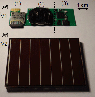
Figure 4(a) Battery-powered platform (with storage memory). (b) Autonomous platform (with solar panel).
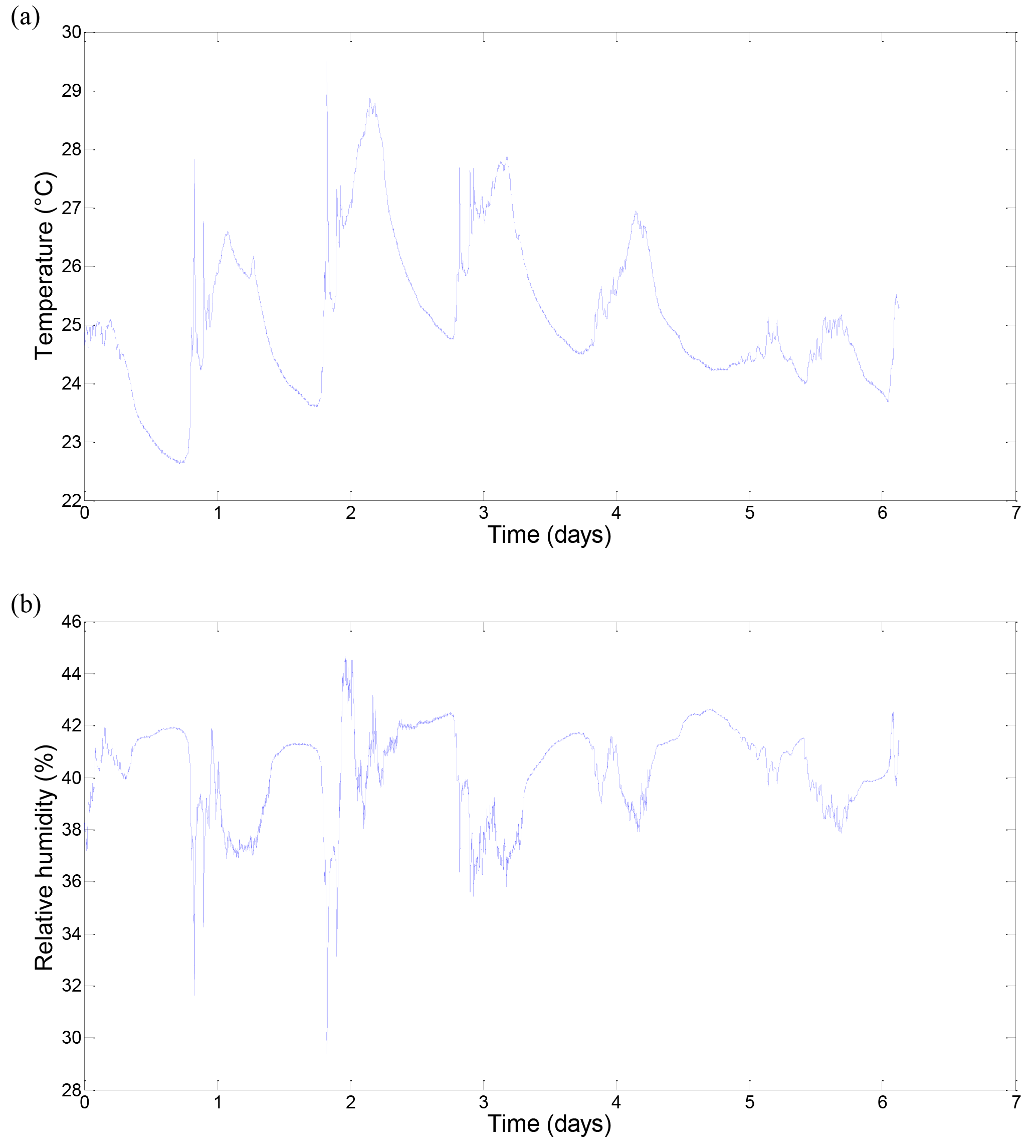
Figure 5(a) Temperature measured by the autonomous platform. (b) Relative humidity measured by the autonomous platform.
Measurements of the evolution of the supercapacitor voltage have been performed on two platforms fixed vertically on the office wall, 3 m far from the window. During the day, lights are turned on and the light level reaches up to 200 lux (measured with an Amprobe LM-100) which is representative to the specifications given by aforementioned Belgian norm. Figure 3 shows the comparison of the standard PMU using standard diodes (V2-A) and the enhanced PMU (V2-B) leading to a lowered voltage drop between the solar cell and the supercapacitor. The platforms are set up in the reference configuration (sampling period = 60 s). During the first 5 days of the week, both platforms are subjected to light 8 h a day. On Friday evening (18:00 LT, local time), they are put in full darkness to assess the autonomy for the worst case (no energy to harvest at all). The last day of the test, the solar cells are exposed to light again. For each platform, we measured the supercapacitor voltage (Vc) and the output voltage at the regulator (VOUT).
Each system accumulates more energy when illuminated during the day (8 h) than it consumes during the night (16 h). After 3 days, the supercapacitor is fully charged and the voltage stabilises at the upper value VC,max.
The autonomy is given by the time elapsing from Friday 18:00 LT when the system is put in full darkness, to the time when the regulated output voltage collapses and the system stops working. Figure 3 shows an autonomy of 60.5 h for the standard diode PMU (V2-A). This autonomy is increased by 51 % to reach 91.7 h on the enhanced PMU version (V2-B), which is even better than the expected 40 % improvement. Even if both PMUs meet the 48 h autonomy requirement, the enhanced PMU provides larger energy storage and shorter start-up time because of a lower bias voltage and more energy remaining in the supercapacitor when the system restarts. Fig. 3b shows that V2-B restarts 90 min before V2-A when exposed to light again.
We measured the power consumption of the functional and sensor blocks together For that, two methods have been used:
-
Integration of the current consumed using a shunt resistor and an oscilloscope to measure the shape of the current and the transients.
-
Supercapacitor discharge using a voltmeter (Druck DPI620) to measure the discharge voltage of the supercapacitor to deduce therefrom the mean current.
For method 2, we evaluated the mean current consumed by measuring the discharge current of the capacitor. Both methods lead to results in good agreement with less than 7 % deviation. The leakage current of the supercapacitor was measured on 10 samples, after a running-in stage of at least 1 week. We configured the system to measure temperature, humidity, luminosity and to send the data to the hub device every 5 s. Between each packet sent the node is in sleep mode. One full charge of the system is enough to power the system for more than 50 h.
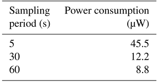
When the microsystem is configured with a sampling period of 60 s (all other parameters being equal), the mean power consumption, integrated over a period, is measured using a shunt and an oscilloscope (method 1): Pcons = 8.8 µW with an RF power of 1 dBm. The results are summarised in Table 4.
We use a 2.4 GHz RF protocol to send the data between the sensor platform and the hub device. We developed our own protocol to allow more freedom and to not be restrained by constraints imposed by general protocols that are not optimized for our system, thus we minimise power consumption. In indoor conditions, the antenna range is typically 20 m due to obstacles, whereas outdoors it exceeds 100 m.
On the receiver side, the hub device receives RF messages containing the sensor data from all nodes in its vicinity. Besides sensors data, the hub device receives the received signal strength indication (RSSI), the state of charge of the supercapacitor and the data loss rate. This enables real-time monitoring of the micro-platform itself. All data can be saved in a CSV file or sent in real-time to a web interface accessible on computer, tablet or smartphone via Wi-Fi or RJ45.
A star network (each node communicating with one central hub device) has been realised with success comprising 10 autonomous platforms (temperature, humidity, luminosity, 1 sample each minute) and five battery-powered platforms (3-axis accelerometer at 100 Hz). RSSI higher than −70 dBm guarantees a very low loss rate (< 1 %) of RF packets.
Finally, we assembled in-house a fully functional system in two versions: battery-powered for industrial applications and autonomous for home applications. The two prototypes are shown in Fig. 4.
The platforms work very well on battery. We tested the autonomous platform under poor lighting conditions. A typical use case is described below. For illustration of a standard use of the platform, data from temperature and humidity sensors are plotted in Fig. 5. The temperature peak at 29 ∘C is observed when the sensor was directly exposed to sunshine. Temperature is rising logically during the day. The decrease rate combined with external temperature variation can lead to a characterisation of the thermal insulation efficiency of the building. The data collected by the device can lead to environment improvement by targeted actions such as efficient insulation or setup of a heating, ventilation and air conditioning (HVAC) system controlled by the output of the sensors.
The relative humidity shown in Fig. 5 seems to be higher during the nights, which is consistent for a closed room since relative humidity is affected by the temperature. The reactivity of the sensors is sufficient for practical applications.
An autonomous micro-platform for multisensors has been developed and customised for a wide variety of applications. For industrial applications with high-speed acquisition requirements (few hundreds of hertz), a battery-powered platform with a small battery was presented. A second model for home and office use, based on the same architecture with the addition of a PMU and a solar cell to harvest energy, has been described.
Both platforms are characterized by compactness and ultra-low-power features. The platforms comprise a microcontroller, a PMU, a power storage unit and an RF front end with an antenna. A large set of low-power miniaturised on-the-shelf sensors can be used to record any measurable input parameters. The power consumption is 8.8 µW (temperature, humidity, luminosity and state of charge with sampling period of 60 s, transmission power: 1 dBm) which should provide an excellent autonomy of 425 days (CR2016, 3 V, 90 mAh) combined in a small volume.
As the system was optimized to be low power – and thanks to its advanced PMU – it can potentially be coupled with a large range of energy harvesters. Powered with solar cells, the system is then able to work indefinitely without failure as long as there is a light source each day. As a worst-case scenario, the system is able to work in the dark for more than 2 days on the supercapacitor with the same settings.
Data are not publicly accessible. All relevant data presented in this article can be made available upon request to the authors.
The authors declare that they have no conflict of interest.
The research has been carried out in the frame of the Remanos and Tracemedia
projects. These projects are performed with the support of the Walloon
Region of Belgium, European Union (ERDF fund) and are carried out by a
consortium of research institutions.
Edited by: Rosario Morello
Reviewed by: three anonymous referees
Bauer, H., Patel, M., and Veira, J.: The Internet of Things: Sizing up the opportunity, available at: http://www.mckinsey.com/industries/semiconductors/our-insights/the-internet-of-things-sizing-up-the-opportunity (last access: 16 April 2018), 2014.
El Chaar, L., Iamont, L. A., and El Zein, N.: Review of photovoltaic technologies, Renew. Sustain. Energ. Rev., 15, 2165–2175, 2011.
Elfrink, R., Nabeto, M., Bembnowicz, P., Tutelaers, M., Stanzione, S., van Acht, V., Uchida, D., and van Schaijk, R.: Harvesting a few µW's is enough, Proceedings of SSI 2015, Copenhagen, Denmark, 149–156, 11–12 March 2015.
EnOcean: PTM 330, available at: https://www.enocean.com/en/enocean_modules/ptm-330/, last access: 28 November 2017.
FOEN Federal Office for the Environment: Batteries, available at: https://www.bafu.admin.ch/bafu/en/home/topics/waste/guide-to-waste-a-z/batteries.html (last access: 16 April 2018), 2016.
Gul, M., Kotak, Y., and Muneer, T.: Review on recent trend of solar photovoltaic technology, Energ. Explor. Exploit., 34, 485–526, https://doi.org/10.1177/0144598716650552, 2016.
Kazmerski, L. L.: Conversion efficiencies of best research solar cells worldwide from 1976 through 2012 for various photovoltaic technologies, National Renewable Energy Laboratory (NREL), 2012.
Kengen, Y.: Piles et énergie grise, Réactif, p. 10, available at: https://energie.wallonie.be/servlet/Repository/reactif_59.pdf?IDR=10149 (last access: 16 April 2018), 2009.
Laurent, P., Maillard, N., Stoukatch, S., Axisa, F., and Destiné, J.: Autonomous micro-platform for multi-sensors (AMM) for wireless monitoring, Proc. smart systems integration Conf. (SSI2013), Amsterdam, The Netherlands, 13–14 March 2013.
Manyika, J., Chui, M., Bisson, P., Woetzel, J., Dobbs, R., Bughin, J., and Aharon, D.: Unlocking the potential of the Internet of Things, Report, McKinsey Global Institute, available at: http://www.mckinsey.com/business-functions/digital-mckinsey/our-insights/the-internet-of-things-the-value-of-digitizing-the-physical-world (last access: 16 April 2018), 2015.
MateriaNova: available at: http://www.materianova.be/, last access: 28 November 2017.
Middleton, P.: Forecast Analysis: Internet of Things – Endpoints, Worldwide, 2016 Update, Gartner, 10 February 2017.
Montgomery, R.: Internet of Things (IoT): market potential + trends in 2017 and beyond, available at: https://www.linkedin.com/pulse/internet-things-iot-market-potential-trends-2017-ryan (last access date: 16 April 2018), 2017.
NBN EN 12464-1: available at: https://www.nbn.be/fr/catalogue/standard/nbn-en-12464-1-0 (last access: 16 April 2018), 2011.
Randall, J. F. and Jacot, J.: The performance and modeling of 8 photovoltaic materials under variable light intensity and spectra, World Renewable Energy Congress VII, Cologne, Germany, 2002.
Texas Instruments: SimpleLink™ Bluetooth low energy/Multi-standard SensorTag, available at: http://www.ti.com/tool/cc2650stk, last access: 28 November 2017.
Torah, R., Glynne-Jones, P., Tudor, M., O'Donnell, T., Roy, S., and Beeby, S.: Self-powered autonomous wireless sensor node using vibration energy harvesting, Meas. Sci. Technol., 19, 125202, https://doi.org/10.1088/0957-0233/19/12/125202, 2008.
Torfs, T., Sterken, T., Brebels, S., Santana-Corte, J., van den Hoven, R., Van Hoof, C., Saillen, N., Bertsch, N., Trapani, D., Zonta, D., Marmaras, P., and Bimpas, M.: Low Power Wireless Sensor Network for Building Monitoring, IEEE Sens. J., 13, 909–915, 2013.
Yue, X., Kauer, M., Bellanger, M., Beard, O., Brownlow, M., Gibson, D., Clark, C., MacGregor, C., and Song, S.: Development of an Indoor Photovoltaic Energy Harvesting Module for Autonomous Sensors in Building Air Quality Applications, IEEE Internet Things, 4, 2092–2103, 2017.
- Abstract
- Introduction
- State of the art
- Autonomous micro-platform concept definition
- Autonomous platform design
- Power source, energy harvesting block and PMU
- Characterisation of the power consumption
- RF communication
- Test in real-world operation
- Conclusions
- Data availability
- Competing interests
- Acknowledgements
- References