the Creative Commons Attribution 4.0 License.
the Creative Commons Attribution 4.0 License.
 | 21 Sep 2018
A new wireless sensor interface using dual-mode radio
Holger Heuermann
Franz-Josef Wache
Rami Audisho Jajo
The integration of sensors is one of the major tasks in embedded, control and “internet of things” (IoT) applications. For the integration mainly digital interfaces are used, starting from rather simple pulse-width modulation (PWM) interface to more complex interfaces like CAN (Controller Area Network). Even though these interfaces are tethered by definition, a wireless realization is highly welcome in many applications to reduce cable and connector cost, increase the flexibility and realize new emerging applications like wireless control systems. Currently used wireless solutions like Bluetooth, WirelessHART or IO-Link Wireless use dedicated communication standards and corresponding higher protocol layers to realize the wireless communication. Due to the complexity of the communication and the protocol handling, additional latency and jitter are introduced to the data communication that can meet the requirements for many applications. Even though tunnelling of other bus data like CAN data is generally also possible the latency and jitter prevent the tunnelling from being transparent for the bus system. Therefore a new basic technology based on dual-mode radio is used to realize a wireless communication on the physical layer only, enabling a reliable and real-time data transfer. As this system operates on the physical layer it is independent of any higher layers of the OSI (open systems interconnection) model. Hence it can be used for several different communication systems to replace the tethered physical layer. A prototype is developed and tested for real-time wireless PWM, SENT (single-edge nibble transmission) and CAN data transfer with very low latency and jitter.
- Article
(1995 KB) - Full-text XML
- BibTeX
- EndNote


In terms of modern applications like “industry 4.0”, cyber-physical systems (CPS) or embedded control systems sensors and corresponding sensor interfaces are becoming more and more important. For the communication a manifold of interfaces and bus systems with different properties are used. Table 1 lists some important sensor interfaces with corresponding properties. Besides tethered communication systems also dedicated wireless solutions are available, like Bluetooth, WiFi or WirelessHART.
To use the communication systems in real-time embedded applications like sensor networks for control systems several requirements have to be fulfilled. Reliable and efficient control systems require timely access to the sensor data, both in terms of latency and jitter (Weiner et al., 2014). Latency is the time it takes for data to be transferred from the sender to the receiver whereas Jitter is the variation of the latency of all the data that are transmitted.
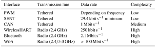
For tethered communication systems the complexity varies from very simple to complex. As each of the bus systems has some pros and cons the most suitable system can be chosen for an application. The complexity of SENT (single-edge nibble transmission) for example is rather low and just a single cable is needed for the unidirectional point-to-point data transmission (SENT, 2016). In addition it can be implemented within a sensor and microcontroller directly without the need of dedicated ICs. However, the data rate is rather low. Data are transmitted in nibbles and coded into the interval between two falling edges of the signal. Therefor the duration of the transmission depends on the values that are transferred, resulting in a data rate between 29.4 and 52.6 kbit s−1. For CAN (Controller Area Network) the complexity is higher, but a bidirectional bus system must be set up. Besides the differential signal transmission on twisted pair cables, dedicated CAN transceiver ICs are also needed. But the data rate is significantly higher compared to SENT (ISO 11898, 2015), depending on the length of the cable. For short cables (<40 m) the data rate can be up to 1 Mbit s−1. Currently a wireless physical layer is not specified for these bus systems that are key communication systems for embedded systems. As a kind of workaround the wireless transmission is done using standard solutions like WiFi or Bluetooth (Ren et al., 2010). In this case the bus data have to be converted into the wireless protocol format before transmission and the receiver converts the data back to the original format. This procedure introduces a large and unpredictable latency and jitter into the data transmission, making real-time applications at least hard to realize or even impossible.
To reduce the amount of cables and connectors and to realize a higher degree of flexibility, wireless communication systems are often used. Standard wireless solutions like Bluetooth or WiFi are commonly used for any kind of communication and many components are equipped with a wireless interface. Even though wireless connections are provided by these systems the communication data from embedded systems cannot be transferred transparently and in real time due to the complexity and the use of high protocol layers (Yu et al., 2011). Dedicated wireless systems like WirelessHART (Hassan et al., 2017) or IO-Link Wireless (Heynicke et al., 2018) are specifically developed to support a wide range of usage cases like closed-loop control in real time. Stability, performance, reliability, jitter and latency can meet the requirements for many applications as well. But this kind of wireless system is dedicated to one communication system only, like in case of the WirelessHART for HART communication.
The capability of dual-mode radio to act as a one-to-one cable replacement is demonstrated using simple and commonly used digital communication systems: PWM (pulse-width modulation), SENT and CAN. A PWM interface is some kind of mixture between analog and digital data transmission as it is value-discrete and time-continuous. As the information is coded into the pulse width of the signal, the setup for the unidirectional point-to-point connection is very simple. The transmitter calculates the pulse width corresponding to the data, and the receiver just measures the width of the pulse using a timer module for example. Both rising and falling edge are steep and hence suitable for timing measurements, e.g. of the latency.
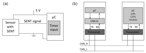
SENT is a digital communication system for the unidirectional data transmission from a sensor to a microcontroller (Fig. 1). It enables a simple, robust and cheap point-to-point connection operating on a time base of 3 µs (SENT, 2016). The data are transmitted in nibbles and the value of each nibble is coded into the time between two successive falling edges. Error detection is done by adding a CRC (cycle redundancy check) to the transmitted data. As the time for the transmission of a nibble depends on the value of the nibble, the data rate is not constant. The minimum data rate for SENT is 29.4 kbit s−1 in the worst-case scenario.
CAN is a multi-master bus system commonly used in automotive and industrial applications. For the bidirectional data transmission, differential signals are used on a twisted pair cable with a maximum data rate of 1 Mbit s−1 (CAN FD runs with 8 Mbit s−1 maximum). OSI layers 1 and 2 are defined in the CAN standard ISO 11898 (ISO 11898, 2015). In general the physical layer is realized by a dedicated CAN transceiver whereas the data link layer is part of a microcontroller. Data transfer between the two ICs is done via RX and TX lines (Fig. 1).
The dual-mode radio uses two free space modes for the unidirectional data transfer and the digital data are represented in different modulations of the simultaneously transmitted radio signals. In the free space we work with two polarizations (e.g. horizontal and vertical). All basic modulation methods can be realized and combined. In this paper the modulation of the data signal by phase modulation is used. The dual-mode radio acts on the physical layer only and the digital data are just converted in hardware to the dual-mode representation and vice versa. This pure physical layer handling enables a real-time communication and the transmission path is fully transparent for digital communication (Heuermann, 2005). The dual-mode radio offers the possibility to replace the tethered communication line of several communication systems by a wireless transmission. Compared to simple on–off keying of the carrier, it provides several advantages. In general, the dual-mode architecture is invariant to phase noise of the oscillator, works with high dispersive antennas and uses a mixer instead of a detector (2 times more dynamic).
Additionally, we use the phase modulation variant of the dual-mode architecture with the better robustness of the phase modulation (Heuermann, 2008).
Figure 2 depicts the general setup of a dual-mode radio system including the transmitter and receiver. The setup is very simple and is built up of just a few components. The transmitter consists of an oscillator, a modulator, an amplifier and two perpendicular oriented antennas. The frequency of the oscillator can be selected to meet the required frequency band, here 4.5 GHz. Other frequencies are possible as well. Due to the coding and decoding of the digital signals the frequency does not have to be very stable, so there are also low requirements on the oscillator. The output signal of the oscillator is split by a 3 dB power divider into two in-phase signals. Within the subsequent modulator each of the two signals is switched by a single-pole double-throw (SPDT) switch to select different paths for the signals. The two different paths include either a 0∘ phase shifter or a phase shifter. The digital data signal (uIF) controls the SPDT switches to switch between a phase shift of 0∘∘ and 0∘∘ respectively. By this switching the phase shift between the two signals after the modulator is 0 or 180∘ representing a digital “0” or “1”. The phase-modulated signals are transmitted by the two perpendicular antennas.
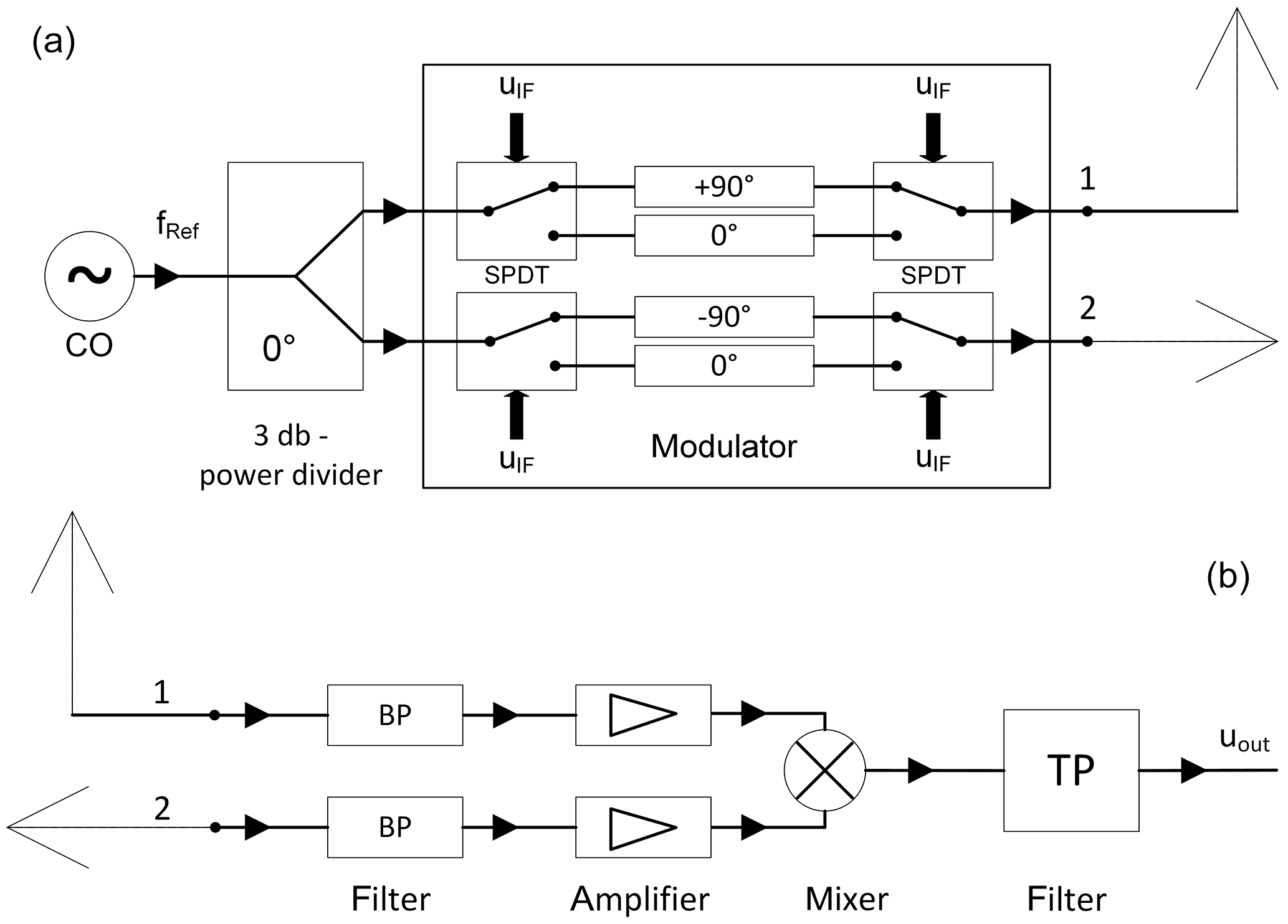
The receiver receives the radio signals, again using two antennas. After an amplification the received signals are connected to the input of a mixer to demodulate the signals. The output voltage of the mixer is negative in case of 180∘ phase shift of the input signals and positive in case of 0∘ phase shift. A low-pass filter filters the mirror frequencies caused by the mixer and a simple electronic converts the resulting signal to the required logic level afterwards.
This method enables a unidirectional wireless communication on a physical layer only, without any protocol or higher layer features. Hence, it can be used for direct cable replacement. For bidirectional communication like the CAN bus the dual-mode system is just duplicated in the other direction. Besides the pure layer-1 functionality, dual-mode radio provides additional advantages compared to other wireless solutions. As described above it is built of just a few components. The transmitter needs a single oscillator without strong requirements with regard to frequency stability or phase noise. The phase shifter and the 3 dB power divider can be realized discrete by using transmission lines, depending on the frequency of the system. The SPDT switches are the critical parts of the discrete system as they mainly determine the maximum data rate. The receiver uses just a mixer and amplifiers if necessary.
The antennas need to be polarized to achieve the usage of two free space modes. In our prototype we use horizontal and vertical polarization, but other perpendicular polarizations such as left-circular and right-circular are also possible. In order to keep the phase difference of 0∘∕180∘ and prevent multipath propagation, the antenna directivity has to be high. Two antennas are needed for both the sender and receiver: in total four antennas for a unidirectional communication. The design of the antennas can be adapted to the requirements of the application.
The transmitter and the receiver are realized on dedicated PCBs to enable maximum flexibility for the usage of the system in prototype systems (Fig. 3). The transmitter converts a digital input into a dual-mode signal and the receivers converts the radio signal back to its digital representation.
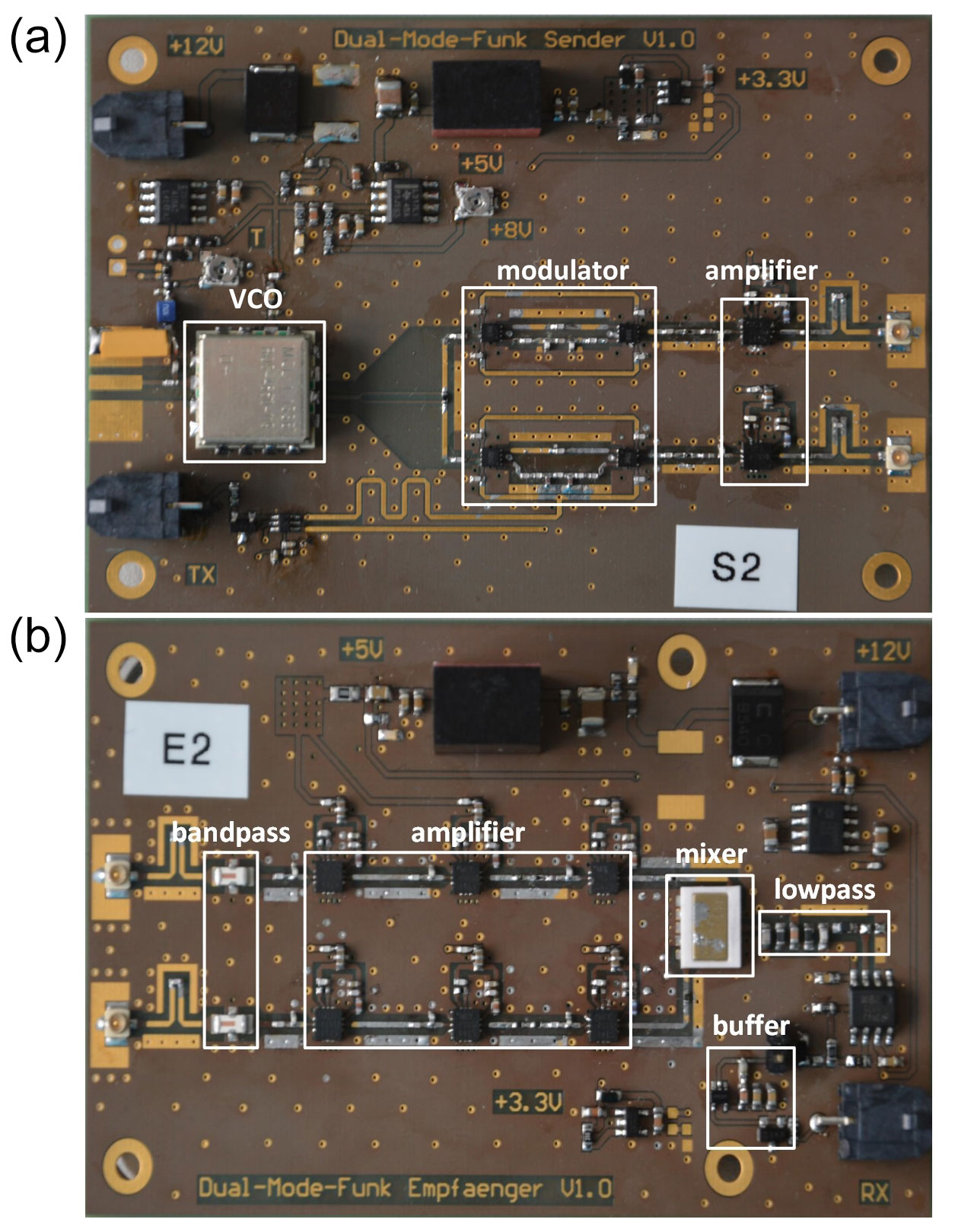
The transmitter is designed for an operation with a bandwidth of 600 MHz (4.2–4.8 GHz) using a VCO (voltage-controlled oscillator). For the 3 dB power divider a Wilkinson divider is used and the modulator consists of four GaAs switches. These SPDT switches provide a switching frequency of about 50 MHz. For the phase shift of a phase shifter of +90 and −90∘ respectively is inserted into the two paths. After the modulator the both signals are amplified to achieve the required output levels. The centre frequency can be chosen as required by the application for next-generation prototypes and systems. The realized system supports a data rate of about 600 Mbit s−1 for the 600 MHz bandwidth, but other bandwidths are also possible, e.g. canals with a bandwidth of 1–10 MHz.
A band-pass filter of 600 MHz filters the received signals and a three-stage amplifier amplifies the filtered signals afterwards to compensate for the losses and to enable a transmission range of about 3 m. After the mixer the demodulated signals are filtered by a discrete sixth-order low-pass filter. A subsequent logic IC generates the digital output of 3.3 V representing a logic “1” and 0 V for a logic “0”.
Simple inverted F antennas were used for the prototype.
4.1 PWM
Data transmission using PWM is very simple and hence enables a basic test of the dual-mode functionality for wireless sensor data transmission. A single transmitter–receiver pair is used for the unidirectional data transfer (Fig. 4). A pattern generator generates the PWM signal that is split into two paths afterwards. One PWM signal is connected to the digital input of the transmitter for the wireless transfer. The digital output of the receiver is connected to an oscilloscope. For comparison the second PWM signal is transmitted via cable (here 2.5 m) and connected to a second input channel of the oscilloscope. This method makes it possible to determine the latency of the wireless link compared to the tethered transmission.
4.2 SENT
The unidirectional SENT protocol provides a slightly higher complexity for the data transmission of sensors compared to the PWM transmission. A Melexis MLX90366 position sensor transmits the measured data via its SENT interface (Fig. 4) (MLX90366, 2015). The SENT data are used as input for the transmitter as well as for tethered transmission. After reception of the data via the two transmission paths (dual-mode radio and cable) they are again connected to an oscilloscope. The received data are decoded by the corresponding function of the oscilloscope. In addition timing measurements are possible as well.
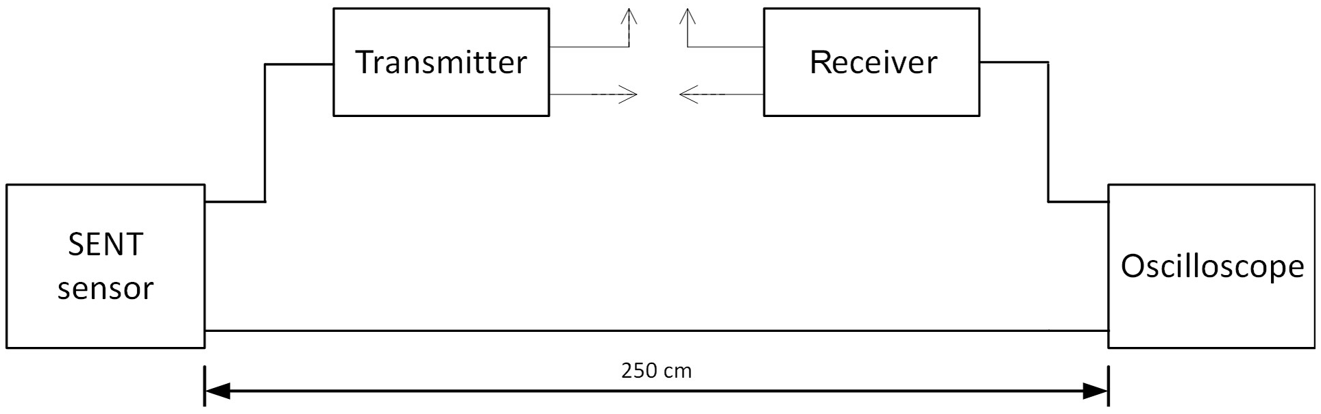
Figure 4Schematic of the SENT setup; for PWM measurement just replace the SENT sensor with a PWM generator.
4.3 CAN
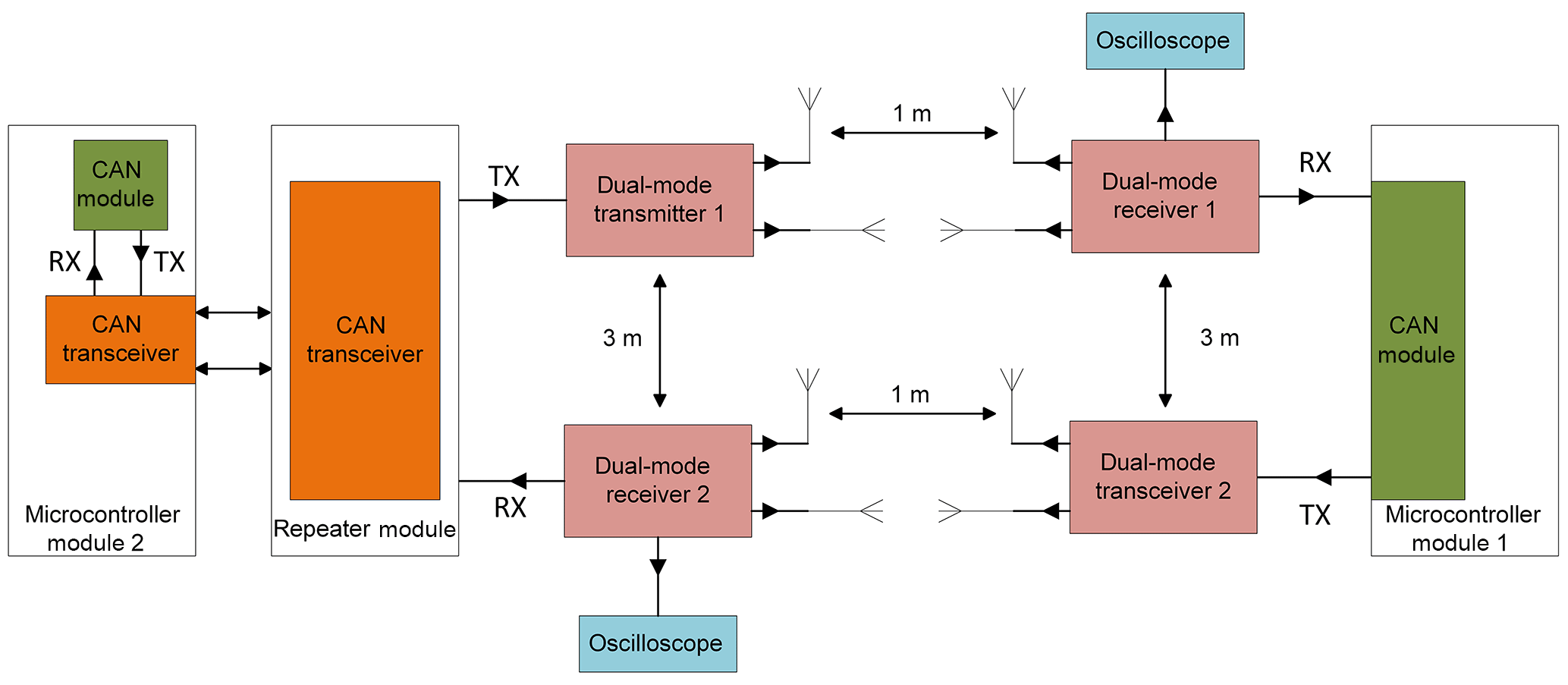
In the current CAN setup the wireless transmission of CAN data is not done on the differential signal lines CAN_H and CAN_L but on the digital signal lines TX and RX between CAN module and CAN transceiver (Fig. 5). The CAN transceiver still converts the differential signals into digital signals and vice versa. Instead of using cable for the transmission of RX and TX data the dual-mode radio system is used. To setup a bidirectional communication two dual-mode transmitter–receiver pairs are used, each operating with two separate antennas (Huening et al., 2018). Hence 8 antennas are required for the bidirectional CAN communication. Due to the simple inverted F-antennas used in the prototype, the separation between the sender and receiver was set to 1 m and between the different directions to 3 m for the measurements of using the prototype. These settings will be changed in case other antennas are used. As the dual-mode radio acts independently from the antennas they can be easily adapted and optimized to the requirements of the application.
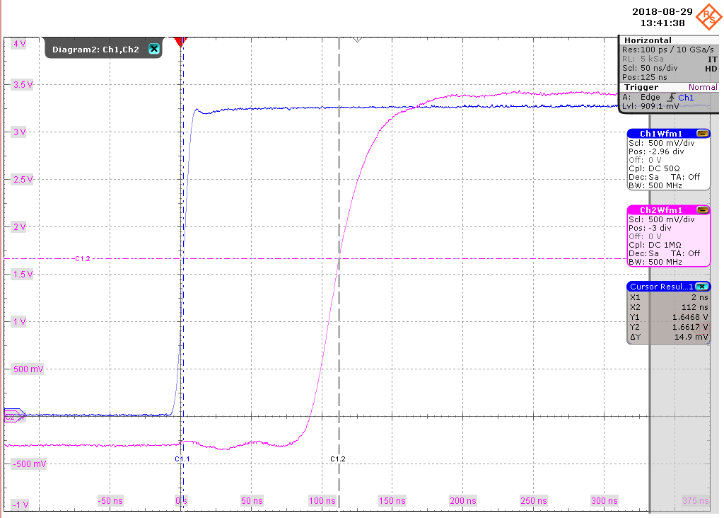
Figure 6Comparison of timing behaviour for PWM transmission via dual-mode radio (purple line) and via cable (blue line).
The three different communication systems are used as prototypes to demonstrate the features of the dual-mode radio for the wireless transmission of digital bus signals. Besides functional tests this demonstration includes timing and error rate tests as well. As shown for the CAN system, the parallel operation of several dual-mode radio transmission using the prototype needs careful setup of the system to avoid overlapping ranges. For future prototypes and system developments, we will work with the frequency multiplex procedure and use additional heterodyne stage for channel selection. Using these improvements will enable the proper operation of several systems in parallel. The robustness against interferences and multipath propagation is similar to other RF (radio frequency) transceiver systems. Using additional noise modulators will improve robustness. The dual-mode radio is very robust against fading and the Doppler effect. Depending on output power the transmitter and receiver can be separated similar to other RF transceiver systems.

Figure 7Comparison of timing behaviour for SENT transmission via dual-mode radio (blue line) and via cable (purple line).
5.1 PWM
The PWM tests are done using a pattern generator for pulse-width generation and an oscilloscope for analysis of the received data. For simplicity a fixed frequency of 5 Hz with a duty cycle of 50 % is used. The data are sent via cable and via the dual-mode system simultaneously to enable a direct comparison between the tethered and radio link. For both links the received pulse width is still 50 %, and there is no deviation from the duty cycle. Timing measurements are done to detect the latency introduced by the radio link including the dual-mode hardware compared to the tethered transmission. Figure 6 depicts the timing behaviour for both the wireless and tethered transmission. The delay introduced by the dual-mode transmission is clearly visible using a rising edge of the PWM signal. Setting the threshold of the rising edge to 50 % of the final high level results in a small delay between tethered and wireless transmission of about 110 ns. Same values are obtained for the falling edge of the signal. Performing several measurements with different PCBs reveal a delay from about 100 to about 300 ns. As this delay is mainly due to the discrete setup of the dual-mode radio we conclude that the delay will be even smaller for a dedicated dual-mode IC.
5.2 SENT
An alternating magnetic field is used for the position sensor to generate different SENT data. The transmission is checked using the SENT decoding option of the oscilloscope. During the duration of the test using the dual-mode radio all SENT data are transmitted correctly, and no single error occurs. The timing measurements are difficult to use for comparison of wireless and tethered transmissions, as the edges of the tethered signal are rather flat (Fig. 7). Nevertheless it is clearly visible that the wireless data generate a steep rising and falling edge.
5.3 CAN
The CAN system is set up according to Fig. 5 and the bidirectional CAN communication between the microcontroller modules is established running at 1 Mbit s−1. Besides the wireless link the system can also use standard tethered RX and TX connections. For the CAN nodes it does not make any difference whether the tethered or the wireless link is used. During the runtime of these application tests no CAN transmission error is observed.
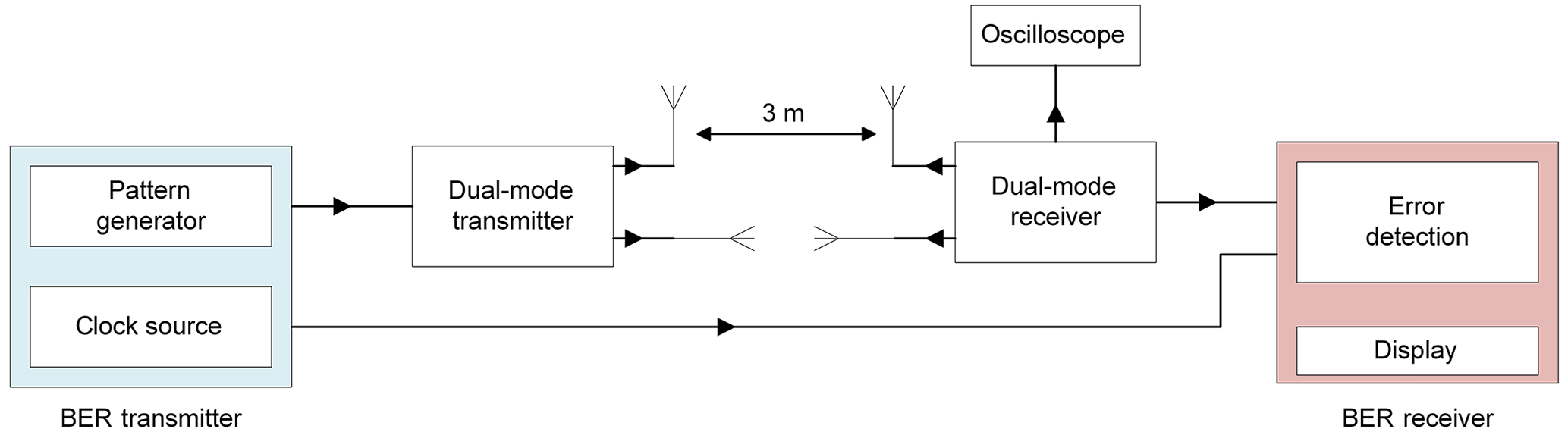
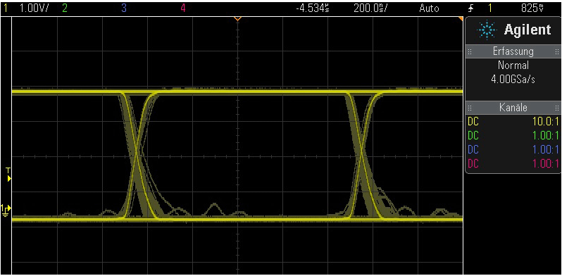
The measurement of the bit error rate (BER) and of the eye diagram is done using a similar setup to that depicted in Fig. 8. The data signal of the BER transmitter is connected to the dual-mode transmitter and the clock signal of the BER transmitter is connected to the clock input of the BER receiver using a coaxial cable. The output of the dual-mode receiver is connected to the data input of the BER receiver. The eye diagram is measured using an oscilloscope.
Both the measurement of the bit error rate and of the eye diagram is done at 1 Mbit s−1, the maximum data rate of high-speed CAN. During a measurement time of 30 min no single transmission error occurred. From statistics this result yields a bit error rate of 10−9. The corresponding eye diagram is depicted in Fig. 9. The eye is widely open and confirms the excellent signal properties as well as the stability of the dual-mode system and a low jitter.
The prototype for the dual-mode radio used in this study is designed in such a way as to combine simple usage and high flexibility. The transmitter and receiver just have a single digital input and output pin, respectively, on the digital part, with the two antenna outputs on the other side. In addition the dual-mode system operates on the physical layer only and converts digital data to the radio representation and vice versa. The functionality of the dual-mode radio system is demonstrated using three different communication systems: PWM, SENT and CAN. For all three communication systems the data transfer runs stably and reliably without any errors and it is fully transparent for the bus nodes. Therefore the system can be used for any kind of wireless data transfer of digital data without any restrictions due to the protocol. As the system is independent of the antennas used for transmission, suitable antennas can be chosen depending on the requirements of the application.
Currently the prototype is built discretely and hence the size of both transmitter and receiver is rather big (10 cm×5 cm each). But the setup of the system is very simple and requires just a few simple components. This simplicity enables the chance of transferring the design into a very small IC. For this transfer there are several different options: dedicated IC for the transmitter and receiver, respectively, will result in the smallest ICs, and for one wireless link one transmitter and one receiver IC is used. Another option is to integrate both the transmitter and receiver into a single IC like for standard CAN transceivers. Still, two ICs will be needed for the wireless link, but this time they will be the same. A third option is to integrate the transmitter and receiver into an existing IC like a CAN transceiver. In this case the number of ICs for the wireless CAN bus is reduced compared to the option with dedicated dual-mode radio ICs. However, this IC is then limited for use in CAN systems.
The current discrete prototype is designed to operate at 4.5 GHz (ultra-wideband), but in general there is no restriction to this frequency or even to the ultra-wideband. Depending on the requirements of standardization, application and the bus system, other frequencies can be used in the final design of the dual-mode radio system, e.g. during the design of a dual-mode radio IC. Higher bandwidth and data rates can also be realized.
Besides the functional proof of the wireless data transfer using dual-mode radio, timing and stability measurements were done. The timing measurements running the PWM data transfer result in a latency of the wireless data transfer of less then 300 ns. A detailed analysis of the discrete setup reveals that this latency is mainly introduced by the SDPT switches. Based on this analysis we conclude that the latency will be significantly smaller when dedicated ICs are used. Detailed jitter measurements were not yet done. But the shape of the eye diagram clearly shows an open eye at a data rate of 1 Mbit s−1, with rather small variation of the slopes. Hence the jitter is low, but a detailed jitter analysis has to be done, in particular to separate the jitter introduced in the dual-mode radio from the jitter by the bus system itself.
Based on the presented results and properties of dual-mode radio, the new wireless link clearly demonstrates its capabilities for a real-time wireless data transfer for embedded bus systems. This system is hence the only known technology for a fully transparent wireless data transmission on the physical layer. The currently introduced latency can be significantly reduced when using a corresponding IC.
In this paper the use of dual-mode radio for wireless sensor interfaces is presented and analysed with regard to example applications, real-time capability and reliability. A discrete prototype for the wireless link is used to realize three different sample applications for PWM, SENT and CAN interfaces. For all three interfaces the wireless data transfer is possible without any restriction. Timing measurements are done using the PWM interface, resulting in a latency of about 300 ns maximum, caused by the discrete prototype. The measurements of the bit error rate and the eye diagram reveal a stable and reliable data transmission using CAN up to 1 Mbit s−1 with low jitter. These results lead to the conclusion that dual-mode radio offers the chance for real-time wireless data transfer for many different embedded bus systems. A transfer of the dual-mode system to an IC will further reduce the latency and hence will enable real-time wireless data transfer for digital sensor interfaces with very low latency and jitter.
The underlying measurement data are not publicly available and can be requested from the authors if required.
HH invented the base technology of the dual-mode radio and proofread the paper. FH supervised the project and wrote the paper, FJW designed the dual-mode transmitter and receiver and performed the CAN measurements, and RAJ performed the timing measurements.
The authors declare that they have no conflict of interest.
The research was funded by the Department of Electrical Engineering and
Information Technology at the University of Applied Science
Aachen.
Edited by: Rosario
Morello
Reviewed by: two anonymous referees
Hassan, S. M., Ibrahim, R., Bingi, K., Chung, T. D., and Saad, N.: Application of Wireless Technology for Control: A WirelessHART Perspective, Procedia Comput. Sci., 105, 240–247, 2017.
Heuermann, H.: Hochfrequenztechnik, Komponenten für High-Speed- und Hochfrequenzschaltungen, Vieweg+Teubner, Wiesbaden, 2005.
Heuermann, H.: Dual Mode Radio: A new Transceiver Architecture for UWB- and 60 GHz-Applications, European Microwave Conf., Amsterdam, 27–28 October 2008.
Heynicke, R., Krush, D., Cammin, C., Scholl, G., Kaercher, B., Ritter, J., Gaggero, P., and Rentschler, M.: IO-Link Wireless enhanced factory automation communication for Industry 4.0 applications, J. Sens. Sens. Syst., 7, 131–142, https://doi.org/10.5194/jsss-7-131-2018, 2018.
Huening, F., Heuermann, H., and Wache, F.-J.: Wireless CAN, Tagungsband AALE 2018, VDE Verlag, Berlin, 2018.
ISO 11898: Road vehicles – Controller Area Network (CAN), available at: https://www.iso.org/standard/67244.html (last access: 3 July 2018), 2015.
MLX90366 data sheet: Rev 1.2, Melexis, 2015.
Ren, Y., Fu, C., Wang, T., and Jia, S.: CAN Bus Network Design based on Bluetooth Technology, 2010 International Conference on Electrical and Control Engineering, Wuhan, China, 25–27 June 2010.
SENT: Single Edge Nibble Transmission for Automotive Applications, SAE J2716 https://www.sae.org/standards/content/j2716_201604/ (last access: 3 July 2018), 2016.
Weiner, M., Jorgovanovic, M., Sahai, A., and Nikolic, B.: Design of a Low-Latency, High-Reliability Wireless Communication System for Control Applications, IEEE ICC 2014 – Selected Areas in Communication Symposium, 2014.
Yu, K., Gidlund, M., Akerberg, J., and Bjoerkman, M.: Reliable and Low Latency Transmission in Industrial Wireless Sensor Networks, Procedia Comput. Sci., 5, 866–873, 2011.
industry 4.0and
internet of thingsapplications. This paper introduces a new wireless communication system that enables real-time and highly robust wireless communication. Using this system makes it possible to transfer any digital bus system transparently. Based on a prototype, measurements and evaluations of the new systems are demonstrated.
industry 4.0and
internet of...