the Creative Commons Attribution 4.0 License.
the Creative Commons Attribution 4.0 License.
 | 08 Jul 2020
Comparison of different fiber coatings for distributed strain measurement in cementitious matrices
Martin Weisbrich
Klaus Holschemacher
Thomas Bier
Distributed fiber optic strain measurement based on Rayleigh scattering has recently become increasingly popular in automotive and mechanical engineering for strain monitoring and in the construction industry, especially structural health monitoring. This technology enables the monitoring of strain along the entire fiber length. This article addresses integrating optical fibers of different coatings into the concrete matrix to measure the shrinkage deformations. However, previous studies do not give a clear statement about the strain transfer losses of fiber optic sensors in this application. In this context, three different coating types were investigated regarding their strain transfer. The fibers were integrated into fine-grained concrete prisms, and the shrinkage strain was compared with a precise dial gauge. The analysis shows a high correlation between the reference method and the fiber measurement, especially with the ORMOCER® coating. The acrylate coating used is also consistent in the middle area of the specimen but requires a certain strain introduction length to indicate the actual strain. The main result of this study is a recommendation for fiber coatings for shrinkage measurement in fine-grain concretes using the distributed fiber optic strain measurement. In addition, the advantages and disadvantages of the measurement method are presented.
- Article
(4517 KB) - Full-text XML
- BibTeX
- EndNote


The development of fiber optic sensors (FOSs), primarily distributed measurement methods, has led to exciting application scenarios in recent years (Udd, 2011; Parker et al., 1997; Czarske and Müller, 1994; Horiguchi et al., 1995). In particular, research groups have published various applications for structural health monitoring (SHM) in civil engineering (Barrias et al., 2018; Inaudi and Glisic, 2005; López-Higuera et al., 2011; Brault and Hoult, 2019). Measurement methods based on Rayleigh, Brillouin, and Raman scatterings are suitable for the measurement tasks in SHM because of their distributed measurement principle. While Raman scattering only measures temperatures, Brillouin and Rayleigh scatterings can measure the temperature and strain (López-Higuera et al., 2011). The difference between these two methods can be found in the spatial resolution, maximum measuring length, and accuracy. Using Brillouin scattering, measurement tasks of several kilometers can be realized with a spatial resolution in the centimeter range (Parker et al., 1997; Leung et al., 2013; Song et al., 2010). Rayleigh scattering used in this study has a maximum measuring length of approximately 70 m and a spatial resolution of a few millimeters (Samiec, 2012).
Distributed fiber optic strain measurement offers essential benefits compared with established measurement methods such as fiber Bragg grating (FBG) sensors, strain gauges, or inductive displacement transducers. In addition to their corrosion resistance, they are dielectric and immune to electromagnetic radiation (Samiec, 2012). Any point of the entire glass fiber can be used as the measuring range for the strain measurement and is not restricted to a predefined section (Weisbrich et al., 2017). Another advantage is the possibility of integrating the fiber into the building material matrix. This enables one to determine strain within concrete components, which can contain information on the curing and load behavior. Especially with massive concrete structures such as foundations or concrete roads, a strain measurement in the matrix can represent the structural and loading conditions. In prefabricated elements, the quality management of posttreatment and health monitoring can be combined. However, information on the deformation within the matrix can also lead to new design approaches in the shrinkage, creep, or swelling behavior of concrete components in research.
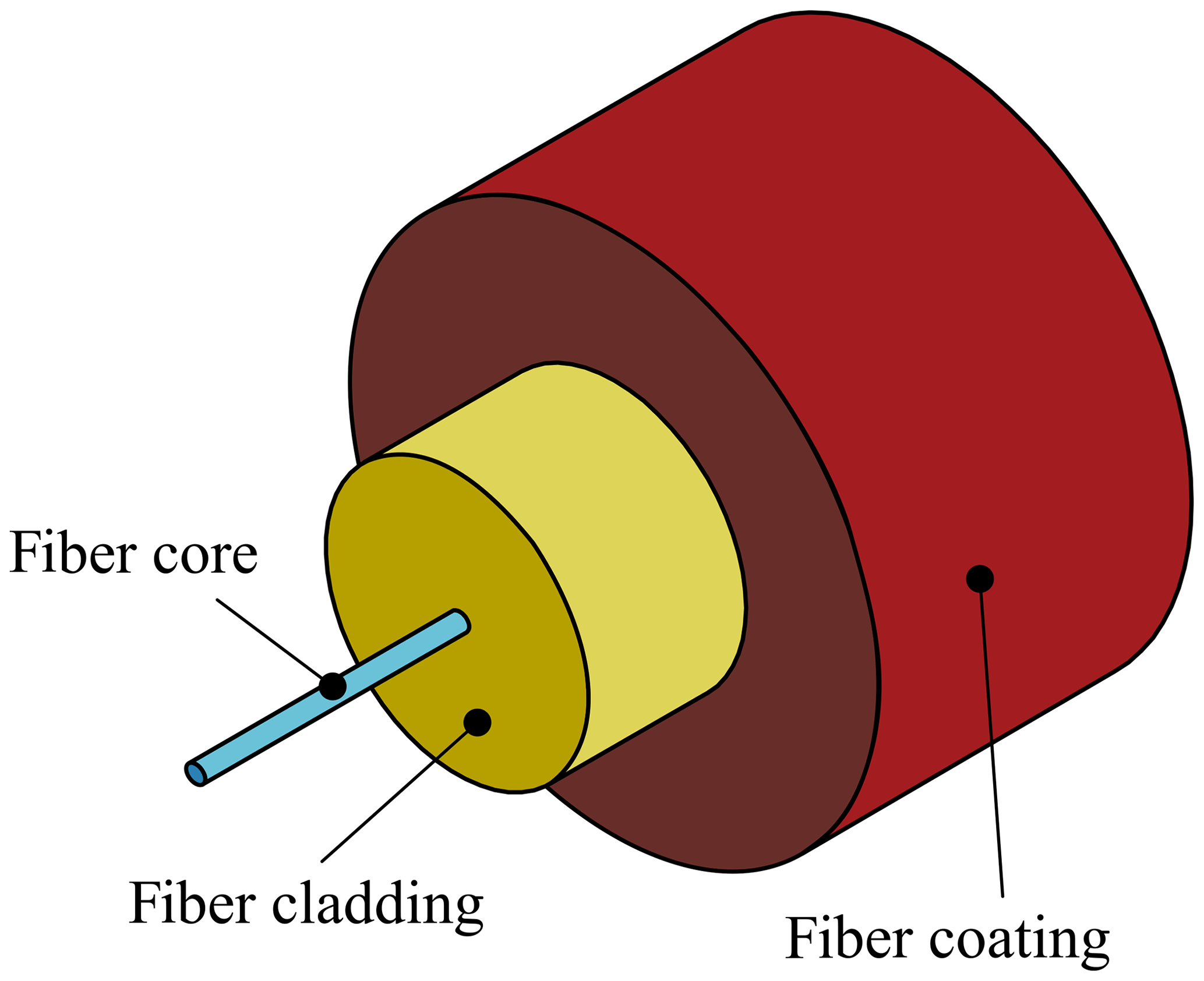
For a realistic representation of the strain in the matrix using FOSs, the investigation of the strain transfer from the substrate to the fiber is a primary factor (Fig. 1). The strain is determined only in the fiber core (Fig. 2). Two mechanisms have a decisive effect on the deformations of the fiber sensors: first, slippage can occur between the fiber cladding (the so-called coating) and surrounding substrate; second, depending on the coating material, the cladding cannot wholly transfer the strain from the substrate to the fiber cladding and the core. The model by Cheng et al. (2005) was modified in this respect and is shown in Fig. 1. The slip relationship between the substrate and the fiber coating largely depends on the curing state of the concrete. Only when the concrete has sufficiently hardened can the strain transfer occur. The bond between coating material and concrete is critical for the strain transfer. For the slip between the fiber coating and the fiber cladding, the stiffness of the coating material is decisive for adequate transfer (Wan et al., 2008; Weisbrich and Holschemacher, 2018; Betz et al., 2006).
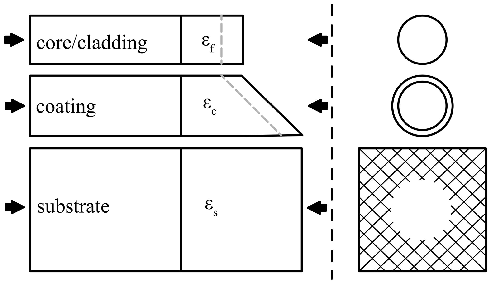
Figure 1Slip relationship between the matrix and the fiber core based on Cheng et al. (2005).
Various research groups have analyzed the effect of the fiber coating on strain transfer during measurements in the matrix. For example, with the help of Brillouin scattering Zeng et al. (2002) determined that fiber cables showed lower strain values in the matrix than the reference method. Li et al. (2002) investigated the strain transfer rates of embedded FBG sensors in mortar prisms. Using a calculation model, the group transferred the lower strain transfer rates (approx. 0.7–0.85) of coating material to the reference measurement level. In 2003, the research group extended its model to include pressure loads (Li et al., 2003). Delepine-Lesoille et al. (2006) validated a developed fiber cable and integrated it into concrete cylinders subjected to compression and tension. Compared with Li et al. (2002), they achieved transfer rates of almost 100 % but only in the range up to approximately −350µε. In 2010, Henault et al. (2010) also used fiber cables to measure the strain in the concrete matrix. In 2012, the research group investigated another type of cable (Henault et al., 2012a). In contrast to the previously presented study, the sensors showed an approximately 20 % lower strain value, so a calculation model for adjustment followed (Henault et al., 2012b). In 2009, Li et al. (2009) examined various strain transfer models for different materials and confirmed them using experiments with sensors bonded to the surfaces. For concrete with a modulus of elasticity of 40 000 N mm−2, the researchers determined transfer rates of approximately 90 %. In this study, experiments on the application in the concrete matrix are missing. Her and Huang (2011) used a test program and a finite element (FE) analysis to established a transfer function, with which the raw data, consisting of high strain losses, could be converted into the real strain. Ohno et al. (2001) integrated FOSs into the compression and tensile zones of a concrete slab and checked the displayed strains. They found that the fiber could not sufficiently anchor in the concrete structure. Bao et al. (2015) used pulse pre-pump Brillouin optical time-domain analysis to measure the shrinkage-induced strain of a cylindrical mortar sample. Their investigation revealed no strain losses between the fiber measurement and the reference method. However, the precise specification of the coating used is missing. In addition, they did not investigate any other coating materials. The research group extended their examination of the measurement of strain in the concrete matrix using distributed fiber optic sensors (DFOSs): in Bao et al. (2017) the research group detected the shrinkage-induced delamination of concrete overlays. They used two different fiber types with a coating diameter of 432 and 1312 µm, respectively. Despite the thick coating, the researchers do not provide any information on the strain losses or compare them to a reference measurement. Davis et al. (2017) investigated the shrinkage-induced strains on a concrete specimen using DFOSs. The researchers bonded the fiber to a reinforcing bar, which they subsequently embedded in the concrete. Compared with the other studies, the authors used rebar as a carrier material. The strain behavior of the fiber directly in the matrix was not examined. Using a brass frame and fiber with a single-layer polyimide coating, Speck et al. (2019) fixed a fiber in small-format concrete specimens and achieved similar values to the reference measurement. In the compression test, the fiber sensors revealed higher values than the strain gauge measurements on the surface.
The publications presented give contradictory statements about the strain transmission performance of optical fibers for measuring strain in the concrete matrix. In some cases, the specification of the coating used was completely omitted. Furthermore, in some investigations, the strain losses at lower loads were considerably higher than those in the tests. This article wants to make a clear statement on the strain transmission performance of optical fibers under shrinkage-induced load. Therefore, the study compares the effect of three different coating materials on the strain measurement of the DFOS in the concrete matrix. Thus, shrinkage tests on fine-grained concrete prisms are used to describe the strain behavior.
2.1 Coating materials and concrete mixture
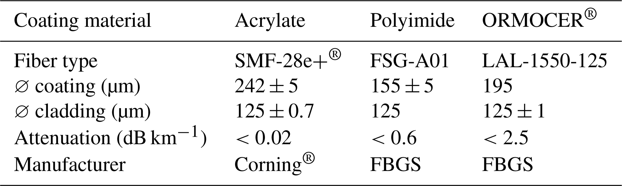
The strain transfer properties of three different coating materials were investigated using shrinkage tests. With two conventional coatings, acrylate and polyimide, the results from the literature should be verified and form a baseline for comparison (Speck et al., 2019; Fischer et al., 2019; Li et al., 2002; Her and Huang, 2011). The third coating material, ORMOCER®, was developed especially for FBG sensors and has shown good strain transfer properties in previous investigations with bonded sensors (Weisbrich and Holschemacher, 2018; FBGS International N. V., 2015). Table 1 summarizes the fiber types and their most important characteristics.
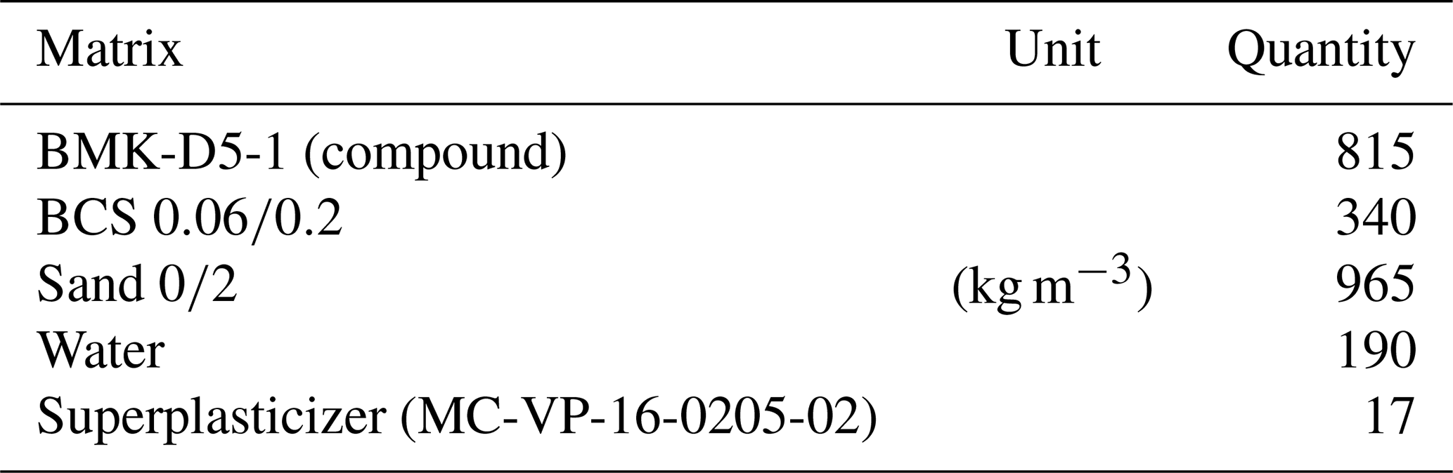
The matrix was a high-strength concrete with a maximum grain size of 2 mm, an elasticity modulus of 45 000 N mm−2, and a compressive strength of 111 N mm−2. Dyckerhoff cement was provided as a compound (Dyckerhoff GmbH, 2017); all other components are listed in Table 2. The fine-grained concrete was selected according to its high shrinkage tendency, which results in a correspondingly high load on the fiber.
Table 2Concrete mixture for the shrinkage tests based on Dyckerhoff GmbH (2017).
2.1.1 Specimens and preparation
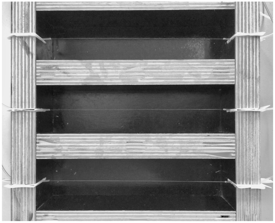
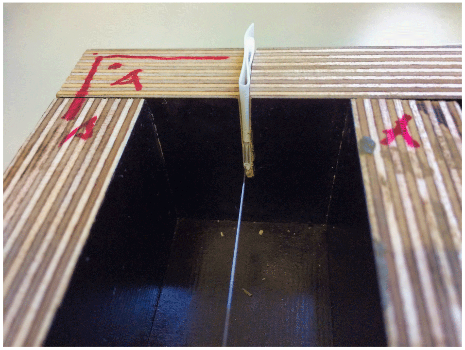
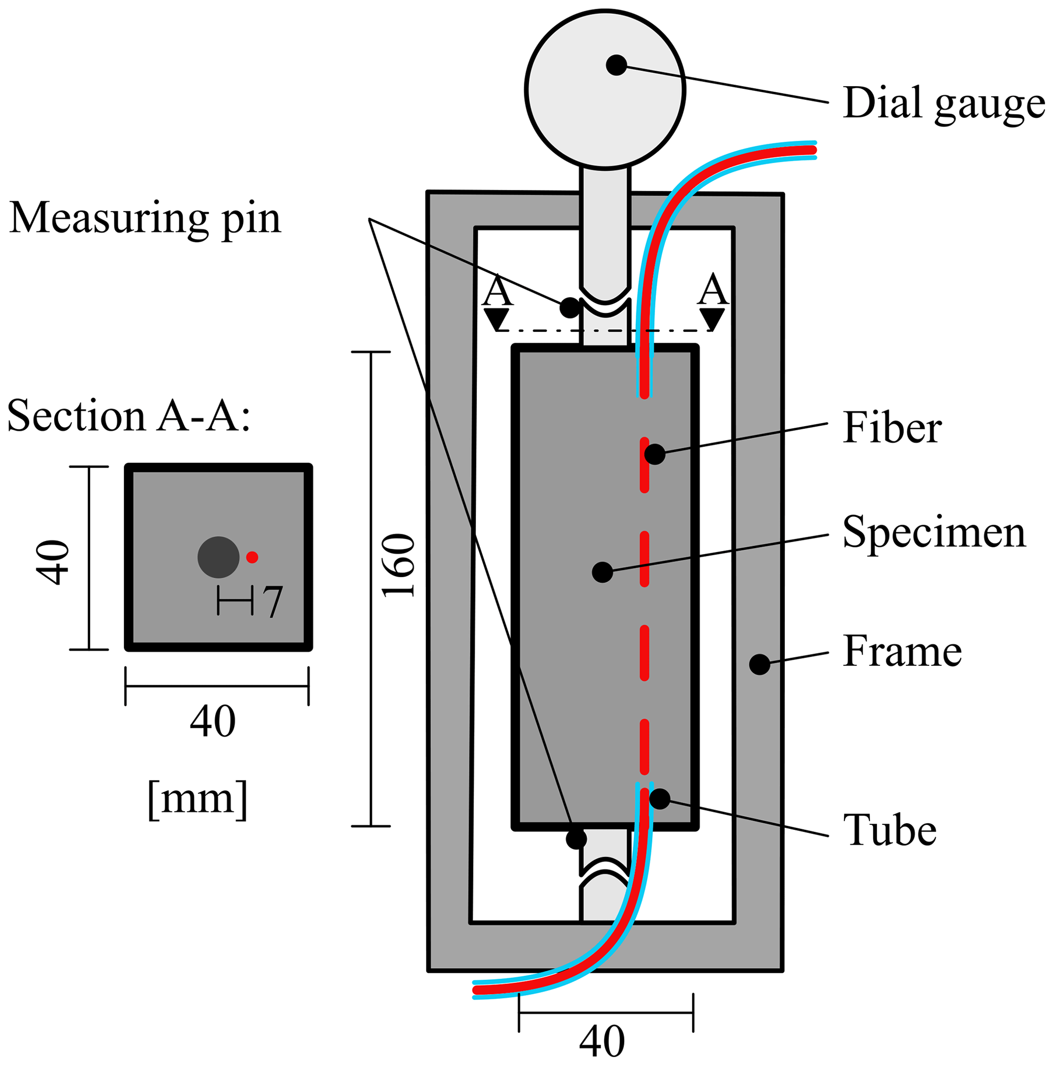
Concrete prisms with b, h, and l dimensions of 40, 40, and 160 mm, respectively, were used as the test specimen geometry. Three test specimens were produced per fiber type, which resulted in a test matrix of nine test specimens (Table 3). To integrate the fiber into the matrix, a modified formwork was used (Fig. 3), where the sensors were clamped and cleaned with isopropanol. Immediately after concreting, the fiber was additionally tensioned to ensure the correct position in the specimen. A Teflon tube was used to minimize the risk of fiber breakage in the outlet areas and protruded 10 mm into the concrete matrix on each end face (Fig. 4). The area protected by the tube was not included in the analysis and is marked accordingly in Figs. 7 and 8. Furthermore, the area with the Teflon tube was used for temperature compensation.
Table 3Specimen assignment and coating material for the shrinkage tests.
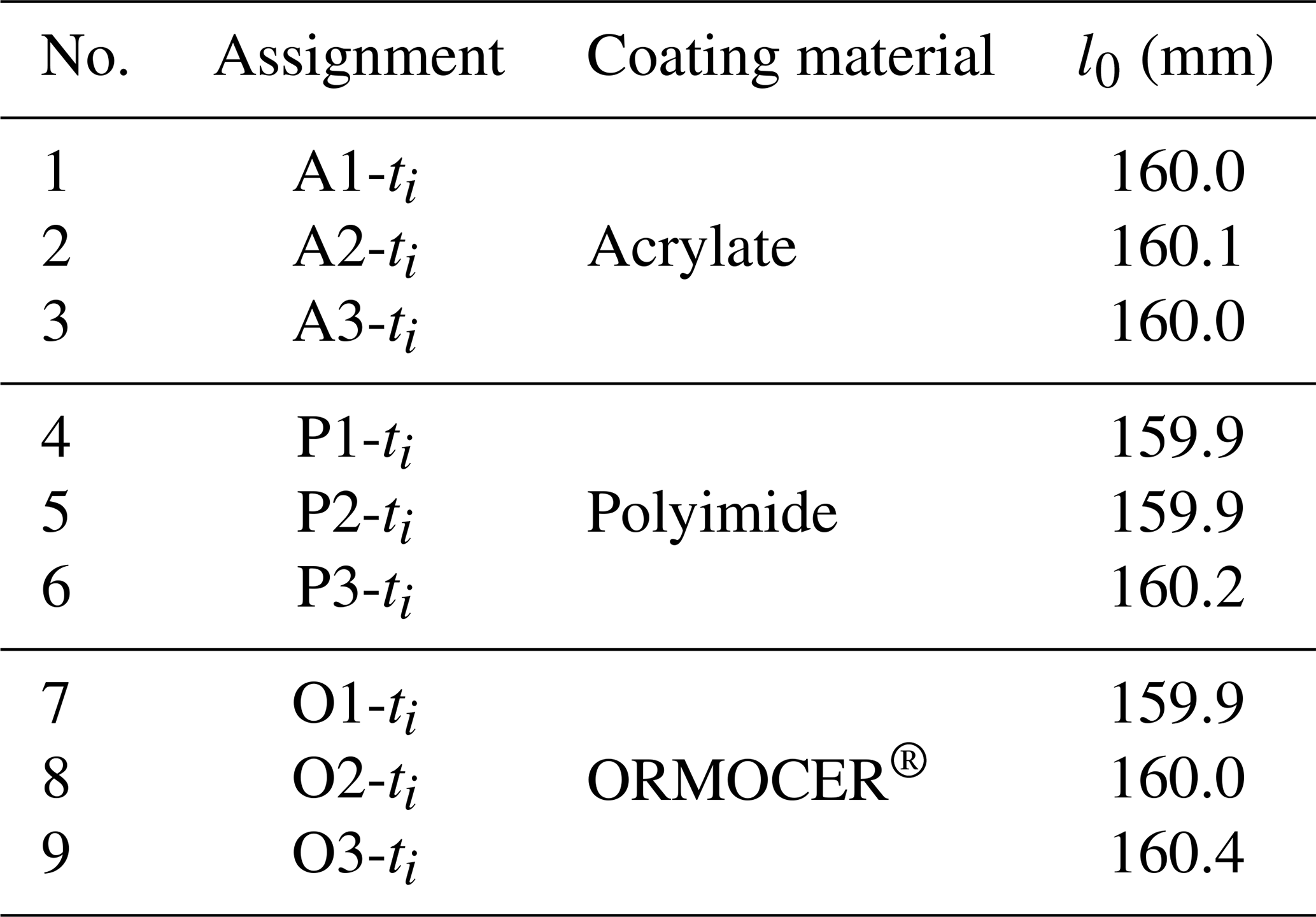
For the reference measurement method, special measuring pins have been glued in the middle of the end faces (Fig. 5). In this regard, the fiber was arranged by an offset dimension of e=7 mm. The null length l0, which is required to determine the reference strain, corresponds to the specimen length. Table 3 summarizes the zero length, specimen designation, and associated coating materials.
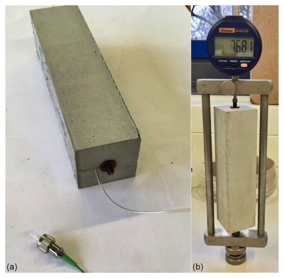
Figure 5(a) Test specimen with sensor fiber and measuring pin; (b) test specimen in the measuring frame.
2.1.2 Test arrangement and procedure
The test setup and procedure are based on the German standard DIN 52450 and are shown in Fig. 6 (DIN 52 450:1985-08, 1985). At 24 h after concreting, the test specimens were prepared for the strain measurement, which proceeded as follows:
-
stripping the test specimens;
-
measuring temperature on the concrete surface with an infrared thermometer to evaluate temperature effects;
-
applying the measuring pins and determining the null length l0;
-
clamping the specimens in the measuring frame (Fig. 5b);
-
reading the reference value t0 for both measuring methods.
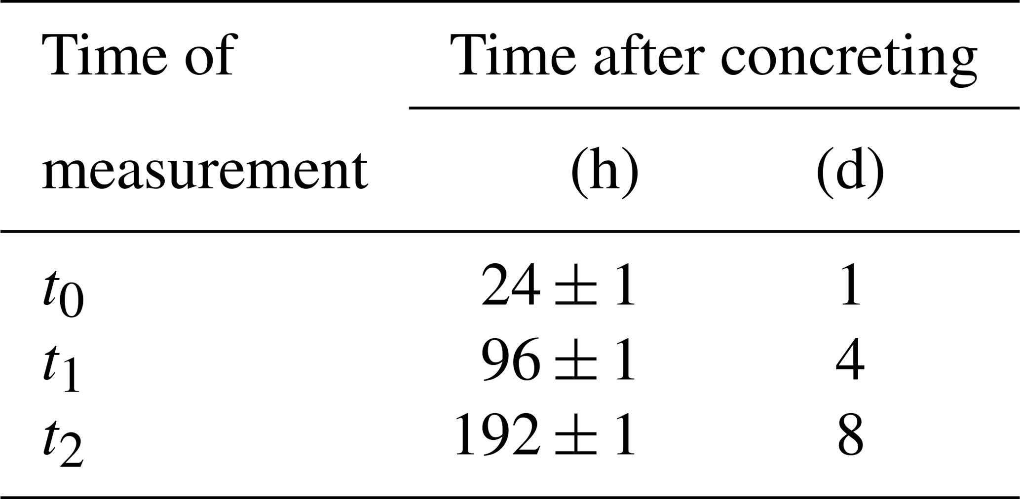
During the experiment, the specimens were stored in a climatic box with constant climatic conditions (39 % RH, 22 ∘C). Due to the relatively low humidity, the shrinkage load needed to be increased. Besides a temperature measurement of the climatic box, a temperature measurement of the sample surface was also used. Due to the low deviation from the ambient temperature (<2 ∘C), the temperature effect on the strain measurement is classified as low. The strain was measured using both measurement methods 4 and 8 d after concreting. The measurement times are listed in Table 4.
2.2 The DOFS system and reference measurement
The strain measurement of the fiber sensors was performed with the interrogator ODiSI-B from LUNA Inc. The interrogator measures the Rayleigh backscattering and uses coherent frequency domain reflectometry to determine the location of the strain along the fiber. Through the frequency shift between the unloaded reference state and the loaded state as well as a subsequent fast Fourier transformation (FFT), the deformations can be determined. Further information on the measurement procedure can be found in the literature (Weisbrich et al., 2017; Samiec, 2012; Gifford et al., 2005; Froggatt and Moore, 1998).
Sensitive digital dial gauges were used as a reference method to measure the length change between the two measuring pins (Figs. 5 and 6). The display of the difference is approximately 0.001 mm; the error limit is 0.0005 mm.
2.3 Evaluation process
The fiber optic measurement method with its distributed measurement generates a considerable amount of data (Weisbrich and Holschemacher, 2018): the method records a strain value for every 2.56 mm of the measuring fiber. To minimize the effect of the measurement noise, the strain values were recorded at a measuring rate of 1 Hz for 30 s at each measurement time ti (Table 4). With a measuring length of 160 mm, 1860 strain values are recorded in the measuring range at each measurement time.
A Python-based post-process was programmed to prepare the measurement raw data accordingly. As the first step, the relevant measurement range was delimited, which results in a matrix X with approximately 62×30 measured values per sample and time of measurement.
Akima interpolation (Akima, 1970) filters system-related measurement errors based on extreme strain variations. The authors achieved better approximations compared with other interpolation or filter methods.
To reduce the measurement noise and improve the comparability with the reference method, the matrix of Eq. ( 1) is combined using a median to form a vector with the strain values:
Figures 7 and 8 show the individual vectors of the respective specimens. Then, the average strain values and standard deviation in the comparison range can be calculated. The results of the comparison range averaging are shown in Table 5; the mean values of the specimens are shown in Table 6.
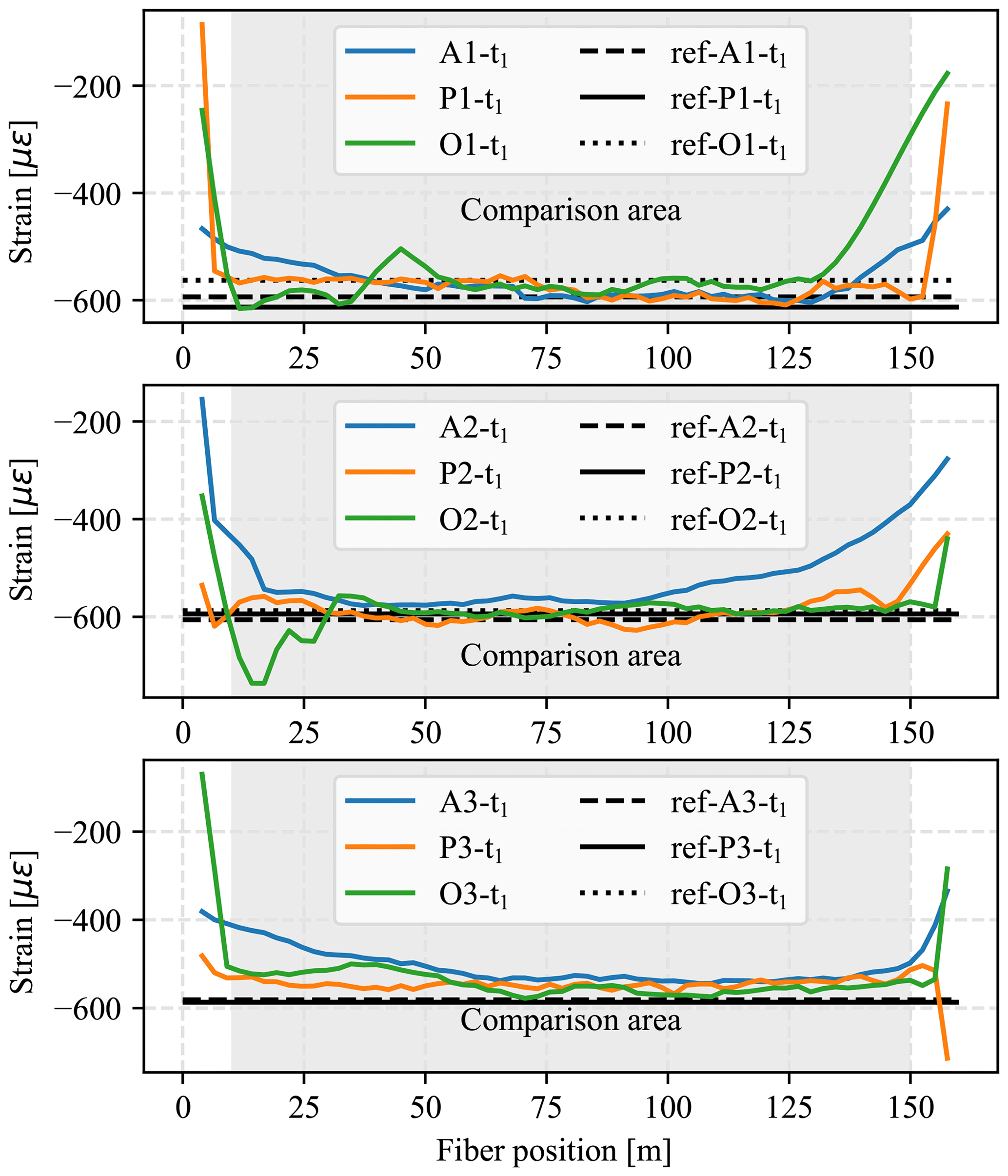
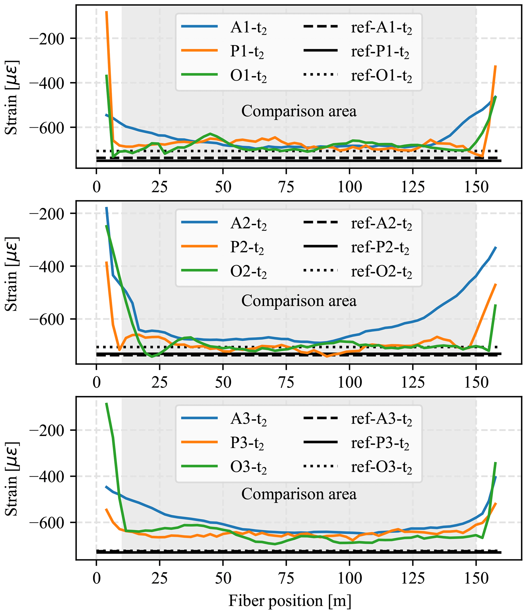
Table 5Strain values and standard deviation in the comparison area of the fiber measurement compared with the strain values of the reference measurement at test times t1 and t2 (in µε).
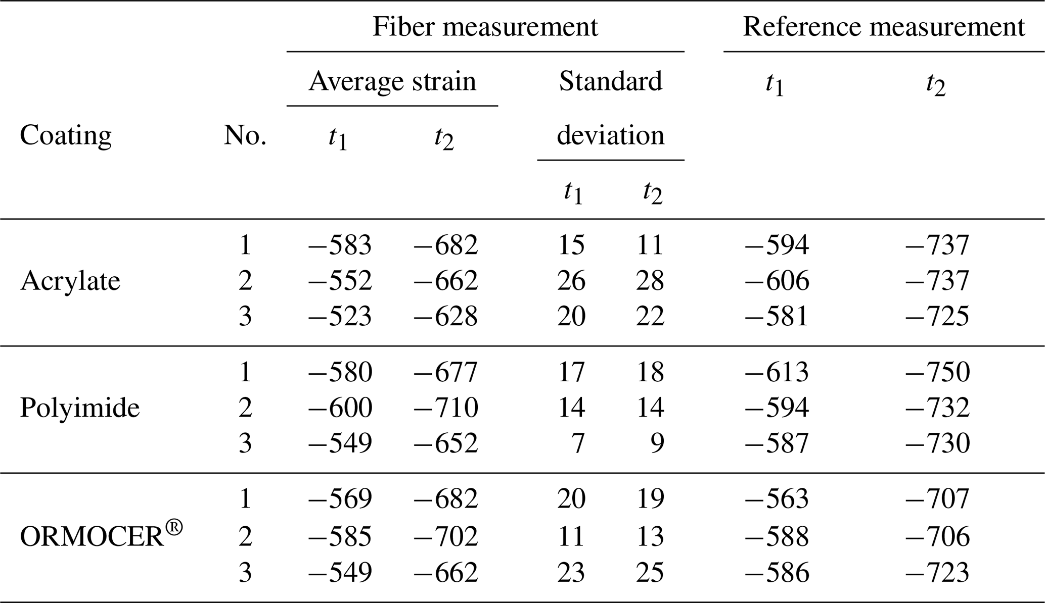
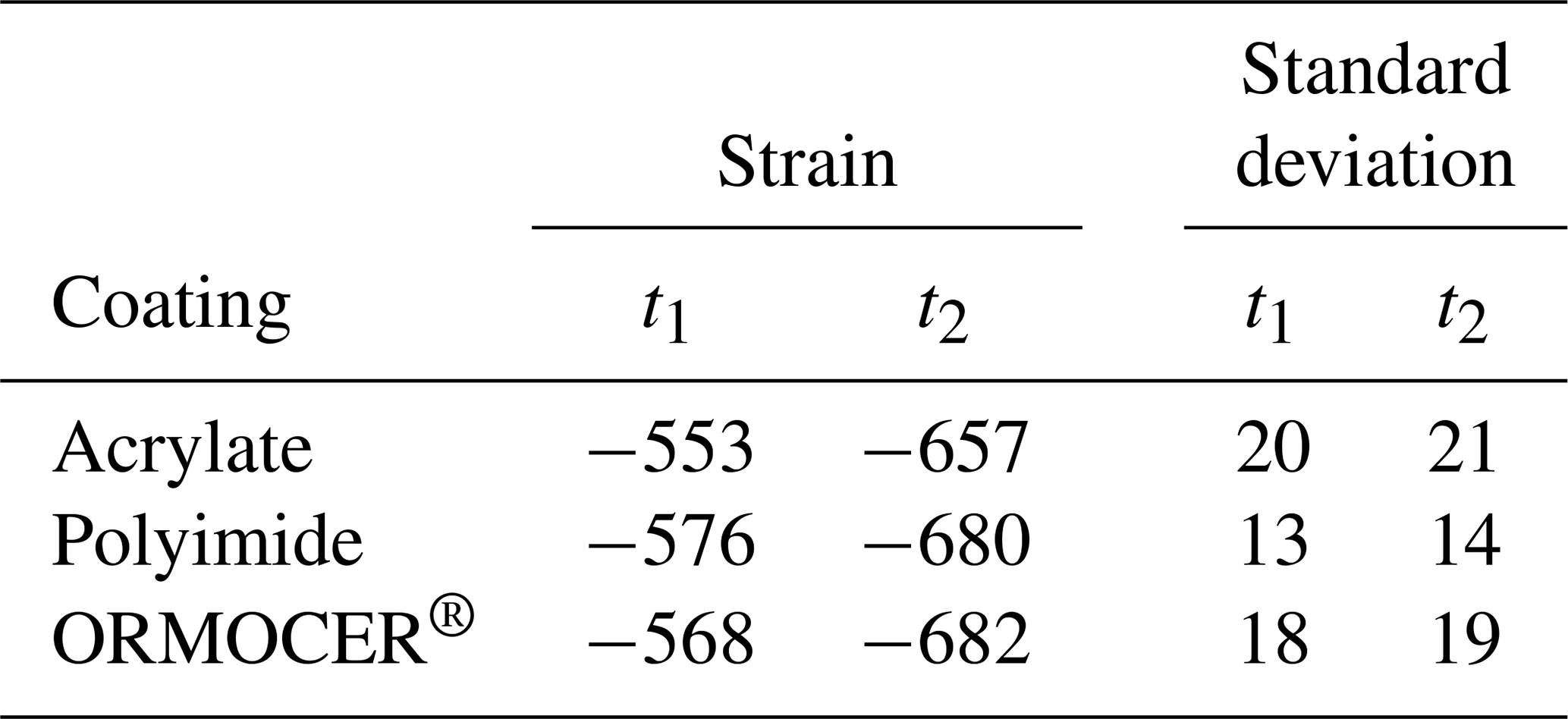
Table 6Average strain values and standard deviation in the comparison area at test times t1 and t2 (in µε).
The primary purpose of the experiments was to investigate the distributed fiber optic measurement method regarding the strain measurement in the concrete matrix. To this end, the shrinkage behavior of nine test specimens with different coating materials was investigated.
An overview of the results of the experiments is shown in Table 5. It contains the mean strain values of the fiber measurement in the comparison range, their associated standard deviation along the fiber, and the respective reference measurement at time points t1 and t2. The strain of the reference measurement results from the reference length l0 (cf. Table 3) and measured value:
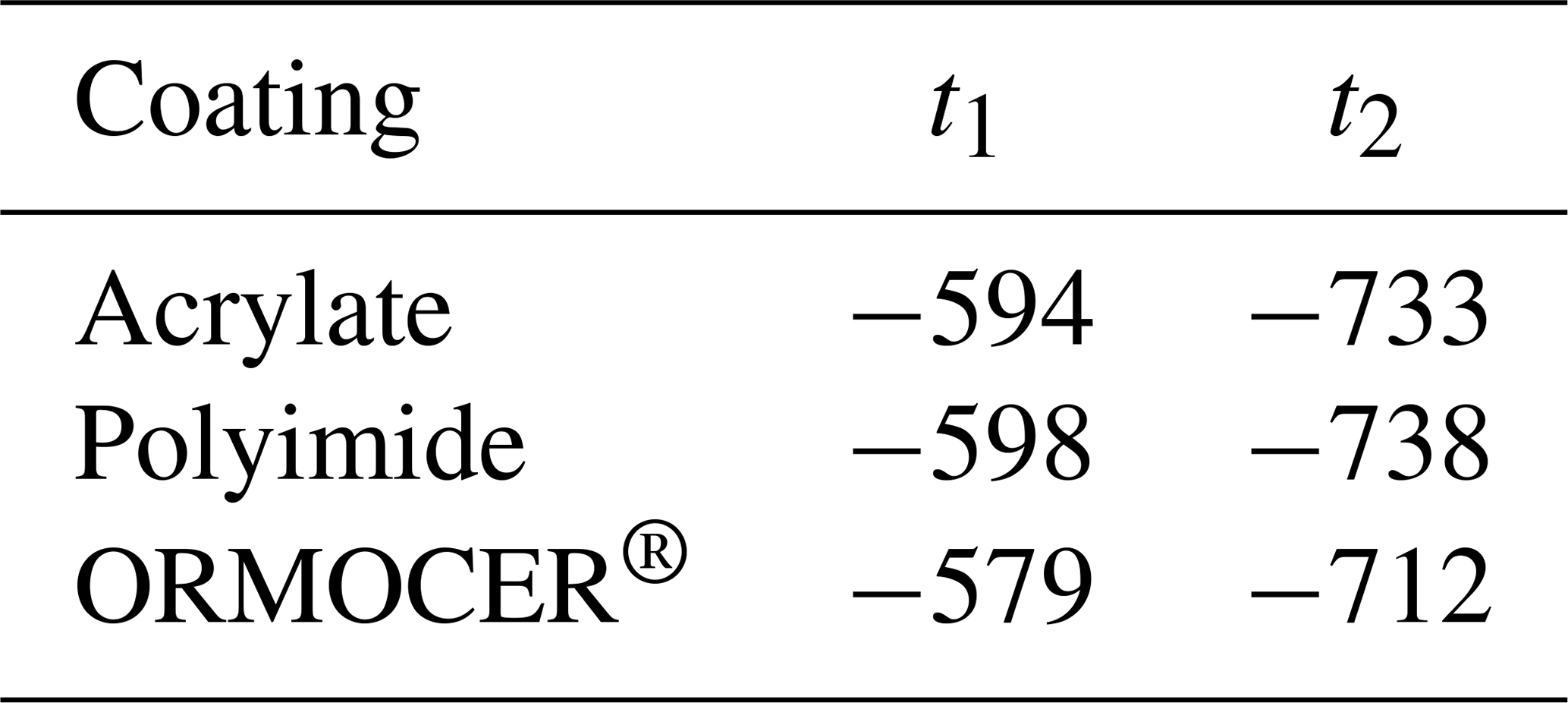
The mean values of the three specimens per fiber coating are shown in Table 6, and those of the reference measurement are shown in Table 7. The comparison of the two measurement methods can be characterized by the quotient between fiber measurement εf and reference measurement εr:
Table 7Average strain values of the reference measurement (in µε).
Figures 7 and 8 show the course of the strain along the fiber for all specimens at t1 and t2. The x axis represents the fiber position, and the y axis illustrates the shrinkage strain. The comparison area where the fiber freely lies in the matrix is highlighted in gray. The 10 mm in the inlet and outlet area indicates the fiber segments where the fiber was protected from mechanical effects by a tube (Fig. 6).
The values illustrate the high correlation between fiber measurement and the reference measurement. Especially with the ORMOCER® fiber coating, the shrinkage strain can be almost completely transferred along the entire measurement length, which indicates a nearly loss-free strain transfer. During the acrylate coating, strain transfer losses were observed in the inlet and outlet areas of the fiber (cf. Figs. 7 and 8); in the center of the specimen, the strain increases to the level of the other two coatings.
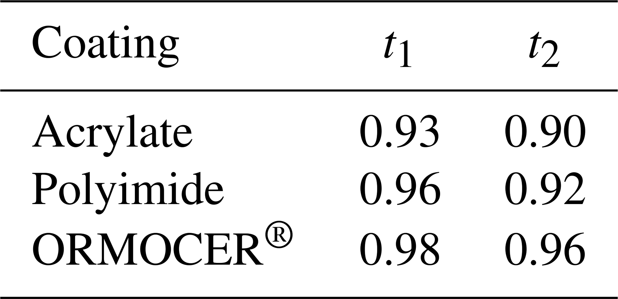
Comparison of the two measurement times t1 and t2 shows strain losses for increasing shrinkage deformation. Although the strain transfer quotient (Table 8) of the acrylate and polyimide fibers decreases by <4 %, the loss in ORMOCER® coating is constant at <2 %.
Table 8Mean strain quotients in the comparison area at test times t1 and t2.
All specimens were similarly produced and show minor artifacts (Fig. 7, specimens O1, O2). Only the ORMOCER® coating indicates a loss-free strain transfer compared with the reference measurement and can be used for shrinkage measurement (t1<2 %, t2<4 %). In the acrylate coating, strain losses were observed in the inlet and outlet areas of the fiber in the specimen, and they indicate a slip between the coating and cladding (cf. Fig. 1). The strains in the middle area of the specimen reached those of the other coating materials. In the case of polyimide and acrylate coatings, small losses (<3 %) were observed between two measurement points during the strain transfer, and losses of approximately 8 %–10 % were found compared with the reference measurement.
In summary, the test design is well suited for assessing the shrinkage behavior with fiber optic strain measurements. Furthermore, the usefulness of the DOFS for the measurement of deformations in the matrix of fine-grain concretes is shown. Compared with the data from Li et al. (2002) and Henault et al. (2012a), all coatings showed significantly lower strain losses. The results indicate that the ORMOCER® coating material can be used for adequate strain measurement in fine-grain concretes. In the case of polyimide coating, small losses of <8 % were observed. Only for acrylate coating should a strain initiation length of at least 40 mm be provided. The lower stiffness of the material may cause poorer strain transfer in these areas. The acrylate and polyimide coatings showed low losses of <3 % at time t2 compared with the measurement after 3 d. The bond between the substrate and coating is assumed to cause the deficits. Except for the entrance area at sample O2 (Table 3, Fig. 7), all specimens were close to each other and only slightly different from the reference measurement. Considering the imprecision of both measuring methods and the fact that the fiber measurement did not cover the whole specimen, the mentioned deviations are negligibly small.
The cause of the artifacts in samples O1-t1 and O2-t1 at positions 20 and 150 mm is not clarified. This could be a measurement error or a partially increased and decreased shrinkage reaction, respectively. As the anomalies occurred in a reduced form at measurement time t2, the authors do not assume a measurement error. Further investigations are necessary for this purpose.
FOS technology offers exciting advantages over the established measurement methods for strain measurement in the matrix. Using the DOFS, the strain can be determined at every point of the fiber, and the sensor fiber can be directly integrated into the concrete structure. Particularly with large concrete components, differences can occur in the shrinkage measurement at the surface compared with that in the matrix. For a strain measurement that corresponds to the real deformation of the component, the strain transfer between substrate and coating and between coating and cladding should be investigated (Fig. 1). Only the frequency shift in the fiber core can be used to determine the strain. In addition to the slip relationship, the correct integration of the fiber into the concrete structure is a challenge. The sensor must retain its intended position even after concreting. Another important aspect is the curing time of the fresh concrete. Only when the concrete has sufficiently hardened can the deformations be transferred to the fiber. In the tests, the measurement was started 24 h after concreting.
The abovementioned tests form a basis to explore the possibilities of the DOFS with respect to measuring the strain in the concrete matrix and the SHM of concrete components, especially for precast elements. Besides, the strain transfer properties of the three coating materials for deformation, measurements in the matrix are evaluated in more detail. However, further investigations are necessary for SHM: for example, the behavior of the fiber sensor remains unclear regarding the position when larger aggregates are used. Another important aspect is the protection of the fiber against destruction. The moisture, aggregates of the concrete, and paving conditions on the construction site are essential in this respect. Strain cables can help here. However, in contrast to fibers that are exclusively protected by the coating, the larger structure of cables increases the slip-related expansion losses. Furthermore, the long-term stability of the sensors is unclear. In particular, the moist, alkaline milieu of concrete can impair the strain transfer during long-term monitoring. In addition to the investigation of other coating materials and cable types, the behavior of the fiber sensors under mechanical loads will be the subject of future investigation. To date, the measuring method has only been tested under pressure loads for the presented case. The strain transfer behavior under tensile loads and the resulting formation of cracks remain unclear.
This investigation compared different coating materials with respect to their strain transfer properties during strain measurement in the matrix using shrinkage tests. If the represented requirements are fulfilled, exact and reproducible results can be achieved using the ORMOCER® coating material. The following conclusions are drawn from the study:
-
The study shows the successful use of DFOSs for strain measurement in the concrete matrix.
-
The measured strain losses are lower than those in the literature; therefore, the use of transfer functions is unnecessary.
-
The test setup is suitable for the validation of different fiber coatings regarding their strain transmission rates.
-
The exact position of the fiber in the matrix during and after concreting is decisive for the indicated strains.
-
The concrete should be sufficiently cured to guarantee the strain transfer. In the tests, the measurement began after 24 h.
-
With the ORMOCER® coating, almost no strain losses were detected at the first sampling time.
-
In the case of the acrylate and polyimide coatings, an approximately 3 % loss occurred between the first and second measurements.
-
The acrylate coating showed higher strain losses in the boundary areas than in the middle of the test specimen (max. 37 %). From a strain introduction length of approximately 40 mm, the acrylate fiber showed strains at the level of the reference measurement and two other coating materials.
-
Due to the immense amount of data, additional post-processes and error algorithms are necessary to exclude system-related measurement errors and precisely display the results.
The datasets used and analyzed in the current study are available from the corresponding author upon reasonable request.
MW performed the experiments with the distributed fiber optic sensors, evaluated the data concerning the topic, and wrote the final paper. KH and TB provided support for the experiments and gave advice regarding the conceptual design of the paper. All authors read and approved the final paper.
The authors declare that they have no conflict of interest.
This research is co-financed by tax revenues based on the budget adopted by members of the Saxon State Parliament (promotion reference: K-7531.20/434-14; SAB no. 100316843). Furthermore, Wiley Author Services proofread the paper.
This research has been supported by the Sächsische Aufbaubank (grant no. 100316843).
This paper was edited by Ravibabu Mulaveesala and reviewed by two anonymous referees.
Akima, H.: A New Method of Interpolation and Smooth Curve Fitting Based on Local Procedures, J. ACM, 17, 589–602, https://doi.org/10.1145/321607.321609, 1970. a
Bao, Y., Meng, W., Chen, Y., Chen, G., and Khayat, K. H.: Measuring mortar shrinkage and cracking by pulse pre-pump Brillouin optical time domain analysis with a single optical fiber, Mater. Lett., 145, 344–346, https://doi.org/10.1016/j.matlet.2015.01.140, 2015. a
Bao, Y., Valipour, M., Meng, W., Khayat, K. H., and Chen, G.: Distributed fiber optic sensor-enhanced detection and prediction of shrinkage-induced delamination of ultra-high-performance concrete overlay, Smart Mater. Struct., 26, 085009, https://doi.org/10.1088/1361-665x/aa71f4, 2017. a
Barrias, A., Rodriguez, G., Casas, J. R., and Villalba, S.: Application of distributed optical fiber sensors for the health monitoring of two real structures in Barcelona, Struct. Infrastruct. Eng., 14, 967–985, https://doi.org/10.1080/15732479.2018.1438479, 2018. a
Betz, D. C., Thursby, G., Culshaw, B., and Staszewski, W. J.: Advanced layout of a fiber Bragg grating strain gauge rosette, J. Lightwave Technol., 24, 1019–1026, 2006. a
Brault, A. and Hoult, N.: Distributed Reinforcement Strains: Measurement and Application, ACI Struct. J., 116, 115–127, https://doi.org/10.14359/51714483, 2019. a
Cheng, C.-C., Lo, Y.-L., Pun, B. S., Chang, Y. M., and Li, W. Y.: An investigation of bonding-layer characteristics of substrate-bonded fiber Bragg grating, J. Lightwave Technol., 23, 3907, https://doi.org/10.1109/JLT.2005.856235, 2005. a, b
Czarske, J. and Müller, H.: Heterodyne detection technique using stimulated Brillouin scattering and a multimode laser, Opt. Lett., 19, 1589, https://doi.org/10.1364/ol.19.001589, 1994. a
Davis, M. B., Hoult, N. A., Bajaj, S., and Bentz, E. C.: Distributed Sensing for Shrinkage and Tension Stiffening Measurement, ACI Struct. J., 114, 753–764, https://doi.org/10.14359/51689463, 2017. a
Delepine-Lesoille, S., Merliot, E., Boulay, C., Quétel, L., Delaveau, M., and Courteville, A.: Quasi-distributed optical fibre extensometers for continuous embedding into concrete: design and realization, Smart Mater. Struct., 15, 931–938, https://doi.org/10.1088/0964-1726/15/4/005, 2006. a
DIN 52 450:1985-08, Testing of inorganic non-metallic building materials, (DIN 52450:1985), 1985. a
Dyckerhoff GmbH: C3 Carbon Concrete Composite, available at: https://www.dyckerhoff.com/documents/209745/0/423C3Bindemittel_D_.pdf/3c690cdd-7df8-c292-83e5-02423d8f2f5d (last access: 7 July 2020), 2017. a, b
FBGS International N. V.: DTG coating Ormocer®-T for Temperature Sensing Applications, available at: https://fbgs.com/wp-content/uploads/2019/03/Introducing_and_evaluating_Ormocer-T_for_temperature_sensing_applications.pdf (last access: 7 July 2020), 2015. a
Fischer, O., Thoma, S., and Crepaz, S.: Quasikontinuierliche faseroptische Dehnungsmessung zur Rissdetektion in Betonkonstruktionen, Beton- Stahlbetonbau, 114, 150–159, https://doi.org/10.1002/best.201800089, 2019. a
Froggatt, M. and Moore, J.: High-spatial-resolution distributed strain measurement in optical fiber with Rayleigh scatter, Appl. Optics, 37, 1735–1740, 1998. a
Gifford, D. K., Soller, B. J., Wolfe, M. S., and Froggatt, M. E.: Distributed fiber-optic temperature sensing using Rayleigh backscatter, in: vol. 3,IET, 2005 31st European Conference on Optical Communication, ECOC 2005, 25–29 September 2005, Glasgow, UK, 511–512, 2005. a
Henault, J.-M., Moreau, G., Blairon, S., Salin, J., Courivaud, J.-R., Taillade, F., Merliot, E., Dubois, J.-P., Bertrand, J., Buschaert, S., Mayer, S., and Delepine-Lesoille, S.: Truly Distributed Optical Fiber Sensors for Structural Health Monitoring: From the Telecommunication Optical Fiber Drawling Tower to Water Leakage Detection in Dikes and Concrete Structure Strain Monitoring, Adv. Civ. Eng., 2010, 1–13, https://doi.org/10.1155/2010/930796, 2010. a
Henault, J.-M., Quiertant, M., Delepine-Lesoille, S., Salin, J., Moreau, G., Taillade, F., and Benzarti, K.: Quantitative strain measurement and crack detection in RC structures using a truly distributed fiber optic sensing system, Construct. Build. Mater., 37, 916–923, https://doi.org/10.1016/j.conbuildmat.2012.05.029, 2012a. a, b
Henault, J. M., Salin, J., Moreau, G., Quiertant, M., Taillade, F., Benzarti, K., and Delepine-Lesoille, S.: Analysis of the strain transfer mechanism between a truly distributed optical fiber sensor and the surrounding medium, in: Concrete Repair, Rehabilitation and Retrofitting III, CRC Press, Cape Town, South Africa, 288–289, 2012b. a
Her, S.-C. and Huang, C.-Y.: Effect of Coating on the Strain Transfer of Optical Fiber Sensors, Sensors, 11, 6926–6941, https://doi.org/10.3390/s110706926, 2011. a, b
Horiguchi, T., Shimizu, K., Kurashima, T., Tateda, M., and Koyamada, Y.: Development of a distributed sensing technique using Brillouin scattering, J. Lightwave Technol., 13, 1296–1302, https://doi.org/10.1109/50.400684, 1995. a
Inaudi, D. and Glisic, B.: Application of distributed fiber optic sensory for SHM, P. ISHMII-2, 1, 163–169, 2005. a
Leung, C. K. Y., Wan, K. T., Inaudi, D., Bao, X., Habel, W., Zhou, Z., Ou, J., Ghandehari, M., Wu, H. C., and Imai, M.: Review: optical fiber sensors for civil engineering applications, Mater. Struct., 48, 871–906, https://doi.org/10.1617/s11527-013-0201-7, 2013. a
Li, H.-N., Zhou, G.-D., Ren, L., and Li, D.-S.: Strain Transfer Coefficient Analyses for Embedded Fiber Bragg Grating Sensors in Different Host Materials, J. Eng. Mech., 135, 1343–1353, https://doi.org/10.1061/(asce)0733-9399(2009)135:12(1343), 2009. a
Li, Q., Li, G., Wang, G., Ansari, F., and Liu, Q.: Elasto-Plastic Bonding of Embedded Optical Fiber Sensors in Concrete, J. Eng. Mech., 128, 471–478, https://doi.org/10.1061/(asce)0733-9399(2002)128:4(471), 2002. a, b, c, d
Li, Q., Li, G., and Wang, G.: Effect of the plastic coating on strain measurement of concrete by fiber optic sensor, Measurement, 34, 215–227, https://doi.org/10.1016/s0263-2241(03)00052-6, 2003. a
López-Higuera, J. M., Cobo, L. R., Incera, A. Q., and Cobo, A.: Fiber optic sensors in structural health monitoring, J. Lightwave Technol., 29, 587–608, 2011. a, b
Ohno, H., Naruse, H., Kihara, M., and Shimada, A.: Industrial Applications of the BOTDR Optical Fiber Strain Sensor, Opt. Fiber Technol., 7, 45–64, https://doi.org/10.1006/ofte.2000.0344, 2001. a
Parker, T. R., Farhadiroushan, M., Handerek, V. A., and Roger, A. J.: A fully distributed simultaneous strain and temperature sensor using spontaneous Brillouin backscatter, IEEE Photon. Technol. Lett., 9, 979–981, https://doi.org/10.1109/68.593372, 1997. a, b
Samiec, D.: Distributed fibre-optic temperature and strain measurement with extremely high spatial resolution, Photon. Int., 6, 10–13, 2012. a, b, c
Song, K. Y., Chin, S., Primerov, N., and Thevenaz, L.: Time-Domain Distributed Fiber Sensor With 1 cm Spatial Resolution Based on Brillouin Dynamic Grating, J. Lightwave Technol., 28, 2062–2067, https://doi.org/10.1109/jlt.2010.2050763, 2010. a
Speck, K., Vogdt, F., Curbach, M., and Petryna, Y.: Faseroptische Sensoren zur kontinuierlichen Dehnungsmessung im Beton, Beton- Stahlbetonbau, 114, 160–167, https://doi.org/10.1002/best.201800105, 2019. a, b
Udd, E.: Fiber optic sensors: an introduction for engineers and scientists, Wiley-Blackwell, available at: https://www.ebook.de/de/product/13230722/eric_udd_fiber_optic_sensors.html (last access: 7 July 2020), 2011. a
Wan, K. T., Leung, C. K. Y., and Olson, N. G.: Investigation of the strain transfer for surface-attached optical fiber strain sensors, Smart Mater. Struct., 17, 035037, https://doi.org/10.1088/0964-1726/17/3/035037, 2008. a
Weisbrich, M. and Holschemacher, K.: Comparison between different fiber coatings and adhesives on steel surfaces for distributed optical strain measurements based on Rayleigh backscattering, J. Sens. Sens. Syst., 7, 601–608, https://doi.org/10.5194/jsss-7-601-2018, 2018. a, b, c
Weisbrich, M., Holschemacher, K., and Kaeseberg, S.: Comparison between different Fiber Optical Strain Measurement Systems Based on the Example of Reinforcing Bars, Proced. Eng., 172, 1235–1242, https://doi.org/10.1016/j.proeng.2017.02.145, 2017. a, b
Zeng, X., Bao, X., Chhoa, C. Y., Bremner, T. W., Brown, A. W., DeMerchant, M. D., Ferrier, G., Kalamkarov, A. L., and Georgiades, A. V.: Strain measurement in a concrete beam by use of the Brillouin-scattering-based distributed fiber sensor with single-mode fibers embedded in glass fiber reinforced polymer rods and bonded to steel reinforcing bars, Appl. Optics, 41, 5105, https://doi.org/10.1364/ao.41.005105, 2002. a