the Creative Commons Attribution 4.0 License.
the Creative Commons Attribution 4.0 License.
 | 17 Aug 2020
Design study for a multicomponent transducer for wind turbine test benches
Jonas Gnauert
Georg Jacobs
Stefan Kock
Dennis Bosse
Benjamin Janik
This paper covers the design study of a multicomponent transducer (MCT) for wind turbine test benches. The MCT will cover the characteristics of wind turbines in the power range of up to 6 MW. The motivation to develop a MCT such as this is to provide satisfying measurement accuracy of loads and moments for all 6 degrees of freedom in order to reduce the uncertainty in the traceability of the drive train behavior due to the applied loads. Therefore, the estimation of the measurement uncertainty is significant with respect to evaluating the design of the MCT. First, the design process of the MCT is briefly introduced. Second, the strain-gauge-based transducer design is investigated under operational conditions (e.g., torque and multiaxial loads) using finite element (FE) simulations to determine the crosstalk effects. Finally, the measurement uncertainties of all quantities are estimated based on these FE simulations according to the type B evaluation of the “Guide to the Expression of Uncertainty in Measurement” (GUM; JCGM, 2010), including metrological aspects (e.g., linearity deviation and hysteresis) and the crosstalk. It can be shown that the MCT has great potential to significantly improve the measurement uncertainty for the applied wind loads on a wind turbine test bench.
- Article
(6269 KB) - Full-text XML
- BibTeX
- EndNote


The wind industry is a major pillar of climate-friendly energy supply in Germany. It supplies 17.2 % of the energy production, which comprises 49.2 % of the renewable resources (AGEB, 2019). To achieve a fully climate-friendly energy supply in Germany, it is important to ensure that the wind industry keeps expanding and becomes competitive with fossil and nuclear sources. Therefore, wind turbines (WTs) must be further optimized with respect to their availability and reliability (BMWi, 2018). Wind turbine test benches (TBs) are crucial to achieve these aims. A conventional TB comprises a prime mover for torque generation on the main shaft, a load application system for the application of wind forces and bending moments, the device under test and electrical power supply equipment, e.g., the converter, transformer and filters (see Fig. 1). Torque generation can be realized with either a high-speed motor in combination with a downstream gearbox or with a low-speed direct drive. Hydraulic actuators realize the generation of the external forces and bending moments. The prime mover and the load application system should have high stiffness and eigenfrequencies along with low damping, and they should be backlash-free to ensure high dynamic load application (Bosse et al., 2013).
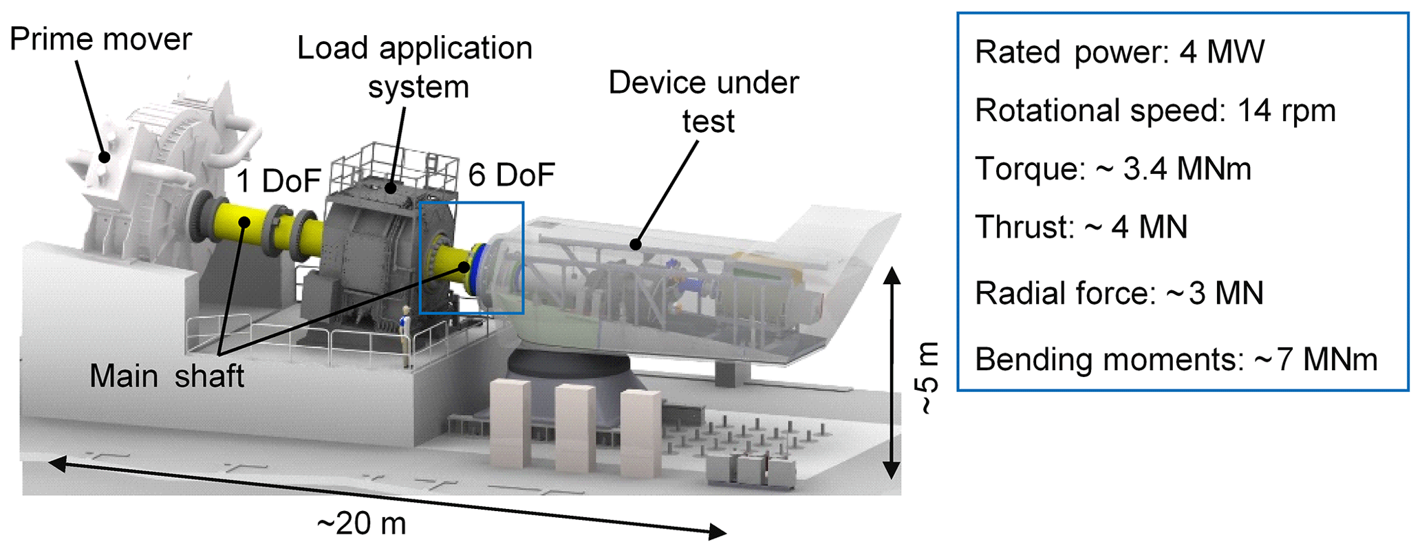
Figure 1A 4 MW RWTH wind turbine test bench (Averous et al., 2015), showing the main components.
Like real WTs, the inclination angle of TBs varies between 4 and 6∘. In most cases, the mounting of the device under test to the TB is realized by adapters and bolt connections. Various devices under test with specific dimensions can be integrated into the TB via the deployment of different adapters and a translational adjustment of the device under test. For the integration of the device under test to the nacelle test bench, the testing facilities are equipped with heavy-load cranes with a load capacity from 100 to 300 t. Therefore, the modern nacelles, e.g., 5 MW power class with dimensions of 6.5 m (height) × 6.5 m (width) ×17 m (length) and a total mass of 290 t, can be lifted and integrated into TBs.
Existing TBs (Bosse et al., 2016), compared with field tests, provide the opportunity to investigate the behavior of the entire drive train and control system under freely adjustable, controlled and reproducible operating conditions. Therefore, it is possible to simultaneously apply multiaxial dynamic wind loads and highly fluctuating electrical grid loads on the WT in order to simulate a realistic load situation. With the 4 MW RWTH nacelle test bench it is possible to apply 3.4 MNm torque under maximum bending moments of about 7 MNm, 3.3 MN radial forces and 4.0 MN thrust (Averous et al., 2015). Thus, exact knowledge of the applied wind loads on a TB is necessary for the determination of the wind turbine efficiency, validation of simulation models and characterization of the drive train behavior under critical operation modes (Kock et al., 2017).
The applied wind loads in TBs can currently only be determined with high uncertainty; for example, the wind loads are calculated by the measurement of the hydraulic pressure in the hydraulic cylinders of the load application system. This method neglects factors such as the speed-dependent friction inside the cylinders. A multicomponent transducer (MCT), which is directly implemented in the power transmission between the load application system and the device under test, would solve this issue. Therefore, a MCT is required to improve the traceability of the applied wind loads, as it is capable of precisely measuring all 6 degrees of freedom (DoFs) simultaneously under rotation. No commercial MCT is currently available for this dynamic and high-load application. Thus, this paper introduces a design study for such a MCT for TBs. As part of this design, a sensitivity analysis with finite element (FE) simulations is executed in order to improve the traceability of the applied wind loads.
Strain-gauge-based force transducers and torque transducers use deformation elements to convert the force or torque to be measured into local strain. The transducer is part of the force transmission and should consequently be relatively stiff to ensure good dynamic behavior (Giesecke, 1994). The transducer only has to be relatively soft at the measuring points to enable high local strains, which are measured by strain gauges. To ensure good measurement results, the measuring points should be located away from the load application, and the strain field should be homogenous at the measuring points (Keil, 1993). To compensate for mechanical sensitivities and temperature influences, the strain gauges are interconnected as Wheatstone bridges (Giesecke, 1994). To use the full potential of the Wheatstone bridges, the deformation elements should have negative strain sections in addition to the positive strain sections (Paul et al., 2014). Depending on the shape of the deformation element, the measurement is based on normal strain, bending strain or shear strain on the measuring points (Giesecke, 1994). Based on these different strain types, different multicomponent transducer designs (Park et al., 2002, 2008; Lietz et al., 2007) are commonly used to measure multiple degrees of freedom simultaneously; the difficulty involved in this process is ensuring that the different components do not influence each other, which is called “crosstalk”. To reduce the crosstalk the measuring body has to separate the components by design, which can lead to complex geometries. The crosstalk of a MCT provides information concerning the sensitivity of each measured component to the influence of the other components and, thus, the quality of the separation by design (Kuttner, 2015). The crosstalk of a MCT is determined via a calibration procedure and should be below 1 % for each component to ensure good measurement properties (Keil, 1995; Schwartz, 2006).
To calibrate a MCT, which would improve the traceability of the applied wind loads in a TB, standard measuring devices are needed. Currently, calibration of a force from 1 N up to 16.5 MN is possible using the standard force measuring devices at the National German Metrology Institute – PTB (Kumme et al., 2008). However, with the planned standard torque measuring devices at the new Competence Center for Wind Energy at PTB, it will become possible to trace torque up to 5 MNm (Härtig, 2018). In addition, the calibration of bending moments will become feasible between 2 and 5 MNm (Frischmuth, 2016). Therefore, this work assumes that the calibration of a MCT such as the one proposed in this paper will soon become possible. As the standard measuring device is still in development, it is currently not possible to include the calibration uncertainties of the standard measuring device in the uncertainty estimation of the proposed MCT.
There are several multicomponent transducer designs available, such as those described by Park et al. (2002, 2008) and Lietz et al. (2007); they are based on cylindrical shapes, tubular shapes, and a combination of bending beams or double-bending beams. These designs can provide high accuracy and have good crosstalk properties; however, designs such as Park et al. (2008), which are based on cylindrical and tubular shapes, have the disadvantage that the measuring capacity cannot be designed individually for each component. The torque transducer (Weidinger et al., 2018, 2019) with additional (non-calibrated) measurement bridges matches the requirements for torque measurement; however, due to its tubular design, the sensitivity of the other components is relatively low. Overall, the necessary measurement capacities for all 6 degrees of freedom is novel for a MCT, which is probably caused by the currently nonexistent (although prospective) calibration possibilities. Therefore, this design study is carried out to identify a suitable MCT design for TBs in order to provide a precise measurement of the applied wind loads with good sensitivity for each measurement.
A MCT between the load application system and the device under test on a TB shows high potential with respect to reducing the uncertainty in the traceability of the drive train behavior due to the applied loads. For this reason, a design study is carried out in order to identify a suitable transducer design. The design study is executed according to the design methodology of the VDI 2221 (VDI, 1993). This methodology divides the design process into four different steps:
-
classification of the task,
-
conceptual design,
-
embodiment design and
-
detail design.
This design study focuses on the first three steps (see Fig. 2).
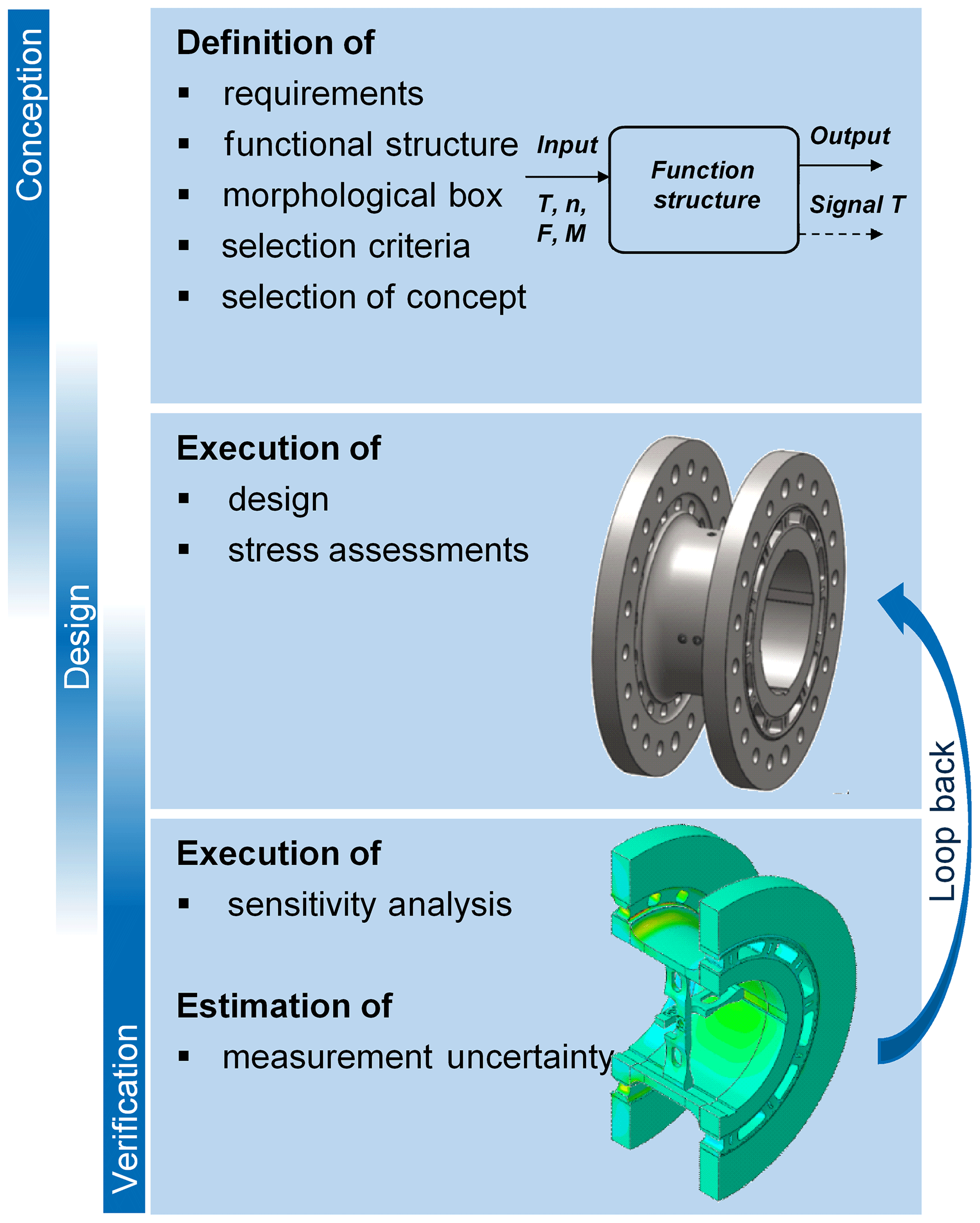
First, the requirements for a MCT are identified and various conceptual designs are developed. Based on a multi-criteria decision analysis, the most suitable design concept is selected and a strain-gauge-based transducer is designed. For this design, a sensitivity analysis using FE simulations is executed in order to improve the geometry concerning the load capacity and measurement range as well as to reduce crosstalk between the measuring points under operating loads (e.g., torque and multiaxial loads). Finally, the measurement uncertainty for each measurement is estimated, taking the crosstalk and the metrological characteristics for strain gauges, such as the linearity, hysteresis and repeatability, into account.
3.1 Classification of the task
For the design study, the characteristics of WTs in the power range of up to 6 MW are considered with respect to the requirements. Considering this power range, the following nominal measurement ranges arise:
-
an axial force of 1.5 MN,
-
a lateral force of 2 MN,
-
bending moments of 5 MNm and
-
torque of 5 MNm.
To achieve a precise measurement with high sensitivity for all DoFs, an individual design for the measurement ranges is necessary. In addition to the individual design for the measurement ranges, the crosstalk between the measuring points must be minimized. The MCT must also fulfill the following general requirements:
-
each measurement uncertainty should be <1 % with reference to the measured value;
-
specific operation conditions, e.g., maximum rotational speed of 30 rpm, must be maintained;
-
specific ambient conditions, e.g., temperature between 15 and 45 ∘C, must be maintained;
-
and specific dimensional conditions, e.g., max diameter of 4.5 m and max length of 2 m, are required.
Based on these requirements, the design concepts are identified in the next design phase.
3.2 Conceptual design
In the conceptual design phase, a functional structure of the MCT is developed. The functional structure identifies all of the necessary functions that must be fulfilled to reach the requirements. Starting from the main function, the “measurement of all 6 DoFs”, the structure is further divided into the main sub-functions of the measurement of each DoF. Every main sub-function is further divided into the following sub-functions:
-
separation of the measurand;
-
conversion of the measurand;
-
creation of the measurement signal;
-
compensation for disturbance quantities;
-
and transfer of the measurement signal.
For each sub-function, various principles are developed that, when combined, are capable of solving the main function (“measurement of all 6 DoFs”). With these design principles, different design concepts are generated, and they are then compared using a multi-criteria decision analysis (weighted sum model). In order to do this, comparison criteria are defined, such as the measurement uncertainty, the sensitivity to disturbance, the possibility of designing the component individually and the manufacturing effort. The criteria are then rated via a direct comparison of pairs. Finally, each design concept is evaluated with respect to the criteria and weighted regarding the direct comparison. The design concept with the highest weighted sum is selected as the most suitable design concept (see Fig. 3) for further investigation.
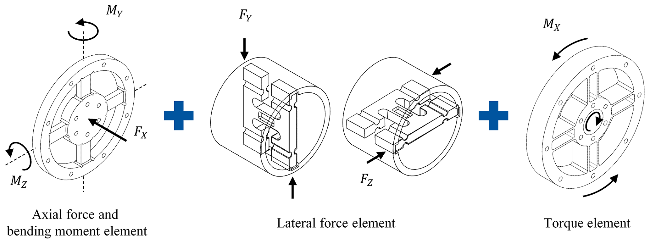
3.2.1 Torque element
To measure torque, a spoked wheel is selected that consists of multiple double-bending beams (see Fig. 4). Double-bending beams offer better accuracy than single-bending beams and provide a higher resistance to parasitic forces. Strain gauges (SGs) will be applied on the double-bending beams to measure the resulting strains εi. The double-bending beams are designed to be sensitive to torque and not to be sensitive to axial and lateral forces or bending moments; this is due to the relatively thin beams in the peripheral direction and the relatively thick beams in the axial direction. Four strain gauges will be installed on each double-bending beam (see Fig. 4), and they will be interconnected using a Wheatstone bridge, resulting in Eq. (1). Using this specific arrangement, the strains at the strain gauges are and (Keil, 2017).
Thus, the torque output signal is proportional to the resulting strains εi at all four strain gauges, which sum to 4 times the average absolute resulting strain due to the alternating algebraic signs of the strain values.
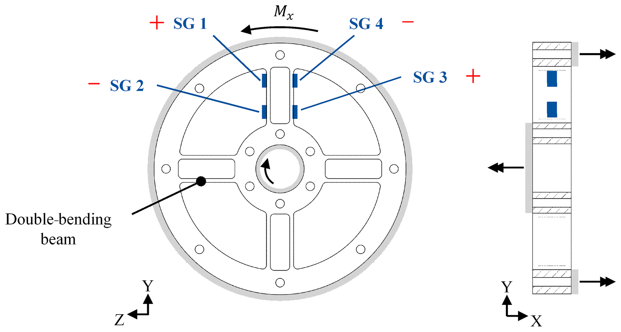
In principle, strain gauges on one double-bending beam are sufficient; however, by taking additional double-bending beams with Wheatstone bridges into account and by averaging all output signals, the signal can be enhanced and the crosstalk effects can be reduced. Additionally, the Wheatstone bridges compensate for crosstalk and temperature effects (Keil, 2017). The spoked wheel design principle of the torque element offers the opportunity to increase or decrease the number of double-bending beams as well as the beams' thickness and length in order to adjust the design to a specific measurement range.
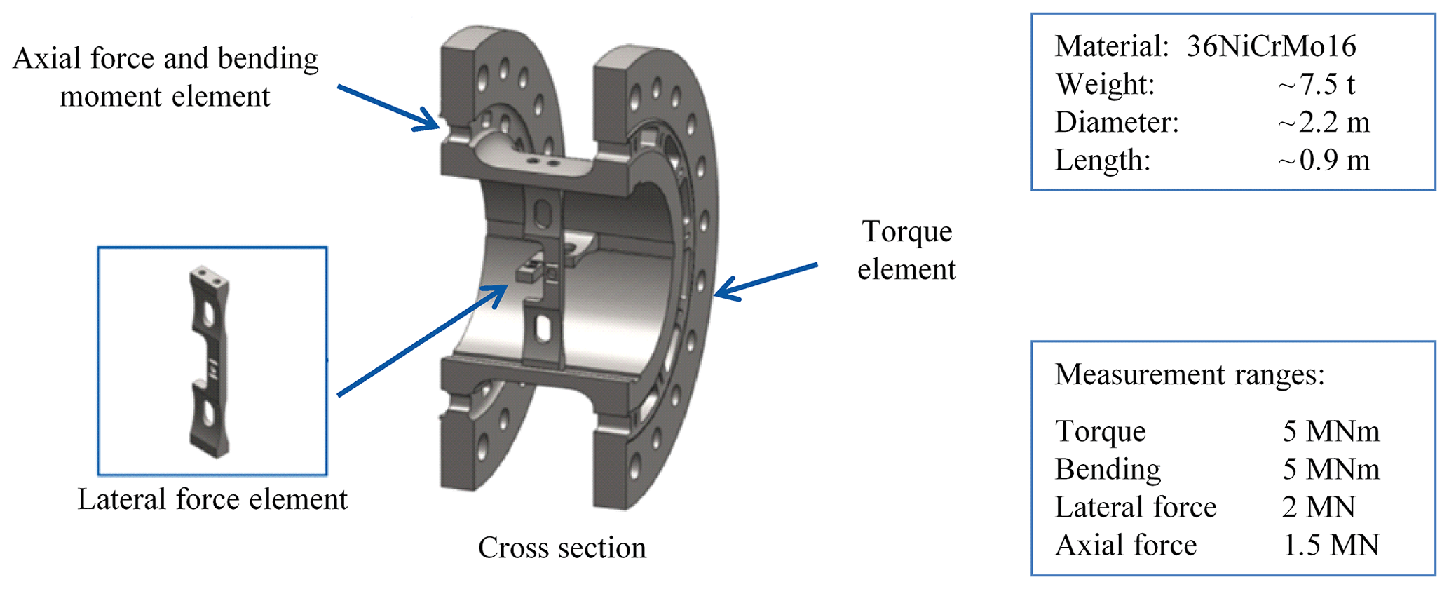
3.2.2 Axial force and bending moment element
A spoked wheel that consists of multiple bending beams is also selected to measure the axial force and bending moments (see Figs. 5 and 6). Strain gauges are applied on these beams to measure the resulting strains εi. The bending beams are designed to be sensitive to bending moments and axial force and not to be sensitive to lateral forces or torque; this is due to the relatively thin beams in the axial direction and the relatively thick beams in the tangential direction. In this case, it is not possible to separate the measurements of “axial force” and “bending moments” via the geometry; hence, it is crucial to separate them through the interconnection of the Wheatstone bridges. The spoked wheel design principle of the axial force and bending element offers the opportunity to increase or decrease the number of bending beams as well as the beams' thickness and length in order to adjust the design to a specific measurement range, although unfortunately not independently of one another.

Four strain gauges will be installed on the bending beams (see Fig. 5) to measure axial force, and they will be interconnected as a Wheatstone bridge, resulting in Eq. (2). Using this specific arrangement, the strains at the strain gauges are and (Keil, 2017).
Thus, the axial force output signal is proportional to the resulting strains εi at all four strain gauges, which sum to 4 times the average absolute resulting strain due to the alternating algebraic signs of the strain values.
In this case, strain gauges on two bending beams would also be sufficient; however, by taking additional bending beams with Wheatstone bridge into account and by averaging all output signals, the signal can be strengthen and the crosstalk effects can be reduced.
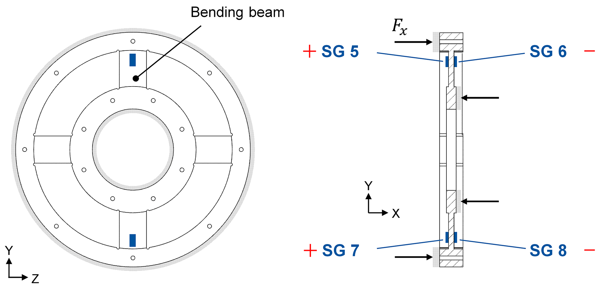
Additionally, to measure bending moments on the same spoked wheel, four strain gauges are installed on the bending beams (see Fig. 6) and are interconnected as a Wheatstone bridge, resulting in Eq. (3). Using this specific arrangement, the strains at the strain gauges are and (Keil, 2017). To determine both bending components, the arrangement must be installed twice vertically with respect to one another.
Thus, the bending moment output signal is proportional to the resulting strains εi at all four strain gauges, which sum to 4 times the average absolute resulting strain due to the alternating algebraic signs of the strain values. The bending element and axial force element shown are just design principles. The application of SG 9 and SG 12 would not be possible because SG 5 and SG 7 would already be attached, respectively. Using several bending beams in the embodiment design, the measuring bridges can be applied to different bending beams.
3.2.3 Lateral force element
An element, which is based on a shear beam (see Fig. 7), is selected to measure lateral forces. Strain gauges are applied on the shear beam to measure the resulting shear strains εi. The lateral force element is designed to be sensitive to lateral forces and not to be sensitive to axial forces, torque or bending moments. Four strain gauges will be installed on the lateral force element (see Fig. 7), and they will be interconnected as a Wheatstone bridge, resulting in Eq. (4). Using this specific arrangement, the strains at the strain gauges are and (Keil, 2017).
Thus, the lateral force output signal is proportional to the resulting strains εi at all four strain gauges, which sum to 4 times the average absolute resulting strain due to the alternating algebraic signs of the strain values.

Lateral forces are transferred through a force shunt into an internally located shear beam, where they result in shear stresses. Besides the lateral forces, the torque and bending moments are also partly transferred to the shear beam. Therefore, a flexure hinge should be implemented in order to reduce the crosstalk effects geometrically. In addition, the design principle of the lateral force element offers the opportunity to increase or decrease the thickness, length and width in order to adjust the design to a specific measurement range. In contrast to the other measurement elements, the lateral force element is not included into one geometrical body; instead, it is inserted into a slot and fixed through a friction-locked screw connection. This connection between the lateral force element and the rest of the geometry must be investigated further. To determine both lateral force components, the arrangement must be installed twice orthogonally with respect to one another.
3.3 Embodiment design
Starting from the selected design concept, the embodiment design of the MCT is created. Therefore, the abovementioned design principles must be combined, and an overall geometry must be shaped. In addition to the requirements for a MCT for a TB, which are presented in the classification of the task, the MCT design should also consider the following criteria:
-
a compact and symmetrical measuring body shape;
-
a one piece measuring body (no moving parts);
-
the measured strain – the relative elongation at the measuring points should be close to 0.1 %;
-
the nominal strains – the relative elongation at the measuring points should not exceed 0.15 %;
-
the homogeneous stress and strain distribution at the measuring point;
-
the fact that the measuring points should be located away from the force application points;
-
and the defined force transmission and controllable force bypasses.
Considering these criteria, the embodiment design of the MCT, which can be seen in Fig. 8, is created. The measuring body of the MCT consists of three main elements:
-
the torque element,
-
the axial force and bending moment element and
-
the lateral force elements.
Strain gauges will be installed on the elements to measure the strain resulting from the input loads. The strain gauges will be connected as Wheatstone bridges. The separation of the single sub-functions in individual elements ensures the possibility to design the measurement ranges independently. This allows for optimization of the measuring points with respect to sensitivity and crosstalk. To achieve these optimizations, a FE model of the MCT is constructed. The strain gauges are modeled using the spring method, following Kock et al. (2018), and the Wheatstone bridges are considered afterwards using an analytical approach. With the help of this FE model, the geometry is optimized concerning the load capacity, the measurement range and crosstalk reduction between the measuring points under operating loads: the axial load, the lateral load, the bending moment and the torque (see Fig. 9).


Figure 10Reduction of crosstalk via an iteration process (loop back): Version 1 shows the initial design (2.68 %), Version 2 displays the demand to bring both lateral force elements closer to the middle plane of the MCT (5.46 %), Version 3 shows the inclusion of additional flexure hinges (2.2 %), and versions 4 and 5 show the optimization of the flexure hinges and profile (1.58 % and 0.61 %), respectively.
Therefore, the operating loads are applied on the MCT, and the signal of each Wheatstone bridge is calculated depending on the simulated strains and the analytics behind each Wheatstone bridge. Thus, it is possible to determine the nominal output signals depending on each nominal load and the amount of crosstalk from another load on an output signal. To reduce the crosstalk, an iteration process (see Fig. 10) is used, which makes it possible, for example, to reduce the crosstalk of a bending moment to the lateral force element from 2.68 % to 0.61 %. Starting from the initial design (2.68 %) a notch is added to the lateral force element to bring both elements closer to the middle plane of the MCT, which results in an increase of the crosstalk to 5.46 %; by adding additional flexure hinges, the crosstalk is reduced to 2.2 %; via optimization of the flexure hinges and the profile as well as additional flexure hinges close to the measuring point, the crosstalk is further reduced to 1.58 % and, finally, to 0.61 %.
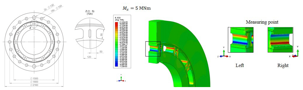
Figure 11Torque element dimensions and the distribution of the nominal strain in the y direction at the measuring point of torque under nominal torque of 5 MNm.
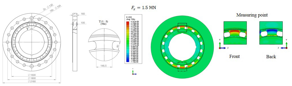
Figure 12Axial force element dimensions and the distribution of the nominal strain in the y direction at the measuring point of axial force under nominal axial force of 1.5 MN.
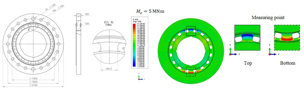
Figure 13Bending element dimensions and the distribution of the nominal strain in the y direction at the measuring point of the bending moment under nominal bending of 5 MNm.
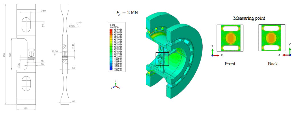
Figure 14Lateral force element dimensions and the distribution of the shear strain in the x–y plane at the measuring point of lateral force under nominal lateral force of 2 MN.
The final MCT design and the strain distribution at each measuring point under nominal load can be seen in the following figures: the torque element (Fig. 11), the axial force and bending element (Figs. 12 and 13) and the lateral force element (Fig. 14). All measuring points show a homogeneous strain distribution and a sufficient sensitivity at the position of the strain gauge application. Despite the FE-based optimization to reduce crosstalk, each component is still subject to crosstalk. The remaining crosstalk in the MCT is summarized in Table 1. By knowing the crosstalk and the metrological characteristics for strain gauges, such as linearity, hysteresis and repeatability, it is possible to estimate the measurement uncertainty for each measurement.
Table 1Crosstalk of each nominal load Fnom,j on the nominal output signal Sj of each measurement, and the combined crosstalk dtalk.

The estimation of the measurement uncertainty for the MCT is performed according to the “Guide to the Expression of Uncertainty in Measurement” (GUM; JCGM, 2010). For the estimated measurement uncertainty, it is assumed that the MCT will be calibrated with the upcoming 5 MNm standard torque measuring device (expected in 2021) at the National German Metrology Institute (PTB; Härtig, 2010) according to metrological standards.
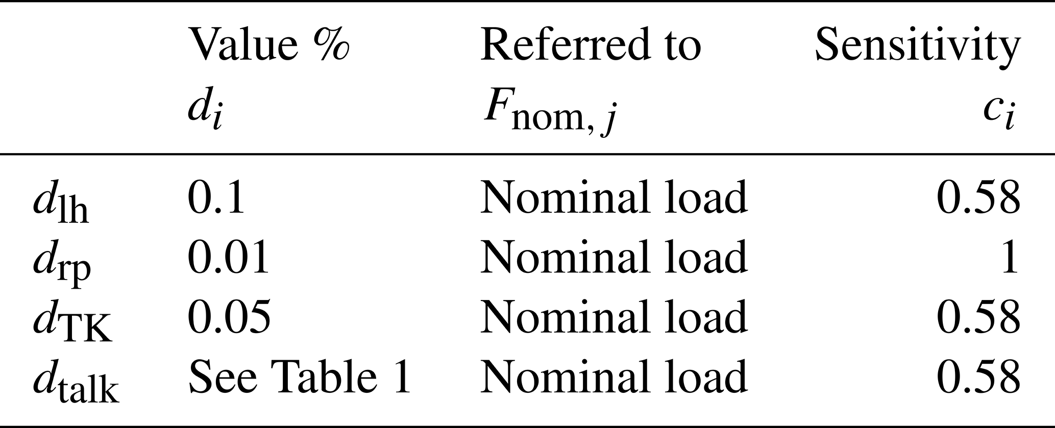
Table 2Relative uncertainty of strain gauges for linearity deviation and hysteresis (dlh), repeatability (drp) and temperature influence (dTK) (Schwartz, 2006) as well as the crosstalk (dtalk).
To estimate the measurement uncertainty, a mathematical model for each measurement of the MCT is defined. The mathematical model of each measurement consists of the analytical formula of Wheatstone bridges:
The k-factor kSG is a strain-gauge-dependent constant, which can vary for each strain gauge. The variation can be controlled by calibration of the MCT. Nevertheless, the strain is affected by linearity deviation and hysteresis (εlh), repeatability (εrp), temperature (εTK), the influence of the bond (εbond), the positioning accuracy (εposition) during bonding and the uncertainties of the calibration procedure (εcali) as well as the crosstalk (εtalk):
For the metrological uncertainty components of strain gauges, values from the literature (Schwartz, 2006) are taken for linearity deviation and hysteresis (εlh), repeatability (εrp) and temperature influence (εTK), whereas the simulated effects are considered for the estimation of the measurement uncertainty for the crosstalk (see Table 2). Uncertainties of the influence of the bond (εbond) and the positioning accuracy (εposition) during bonding as well as the uncertainties of the calibration procedure (εcali) are currently not considered. Additionally, probability density functions for the uncertainty components are assumed to be a uniform distribution except for the repeatability, which is assumed to be a normal distribution. By knowing the crosstalk and the uncertainties of strange gauges, it is possible to estimate the expanded measurement uncertainty according to the GUM (JCGM, 2010). With the distributions, the absolute standard uncertainty ui of each uncertainty component is calculated following Eq. (7):
where the sensitivity ci is the standard uncertainty of the chosen distribution, and di is the relative uncertainty of the different uncertainty components. The combined uncertainty uc is then calculated from the absolute standard uncertainties of the uncertainty components with respect to the mathematical model and the law of propagation of uncertainties:
By taking a coverage probability of 95 % (k=2) into account, the absolute expanded measurement uncertainty is calculated following Eq. (9) (see Table 3).
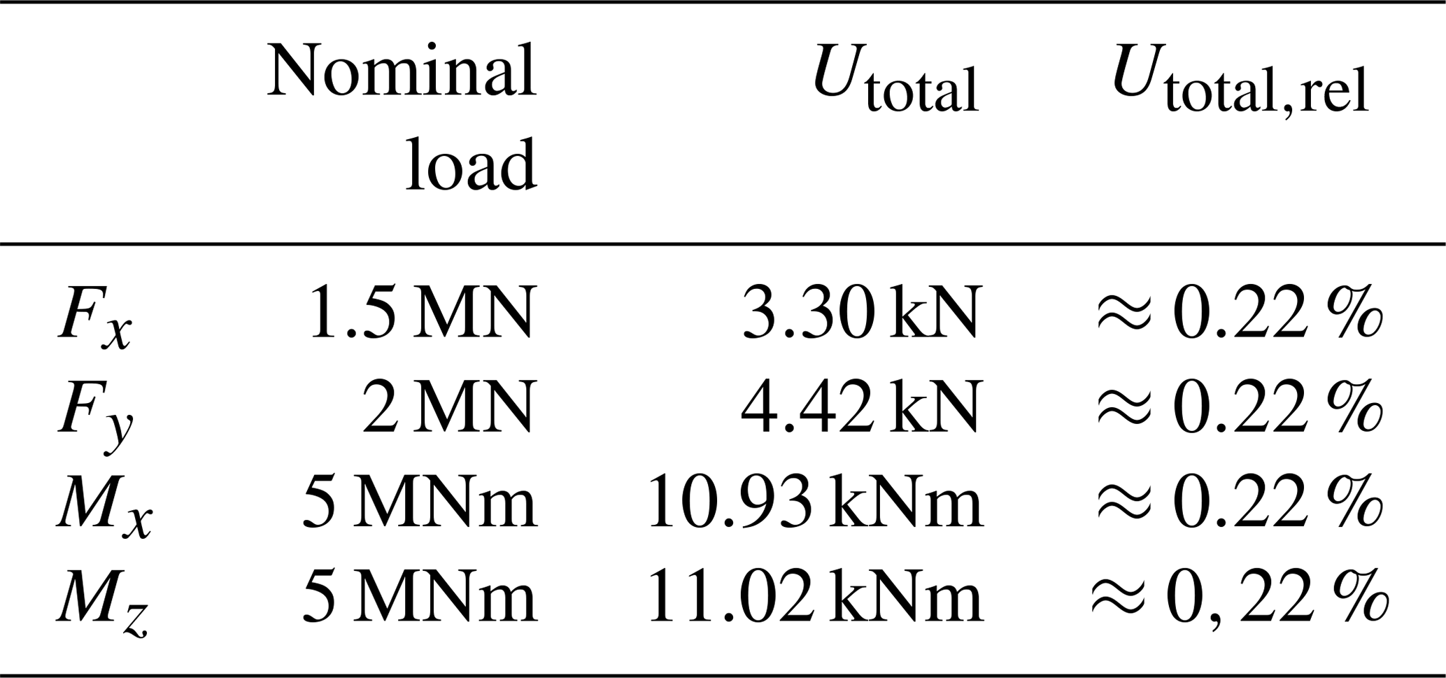
The relative expanded measurement uncertainty of each measurement is approx. 0.22 %. This first estimation of the relative expanded measurement uncertainty includes linearity deviation and hysteresis, repeatability, temperature influence and the simulated crosstalk. Uncertainties of the influence of the bond and the positioning accuracy during bonding as well as the uncertainties of the calibration procedure are not currently considered. Nevertheless, the authors are confident that this first estimation shows great potential for the proposed MCT to meet the proposed requirement of a measurement uncertainty for each measurement of below 1 %.
This paper shows the design study of a MCT for TBs. The developed MCT show great potential for precise measurement of all 6 DoFs in their own individual measurement ranges. A first estimation of the measurement uncertainty shows that the expanded uncertainties are below 0.5 % for all components. This includes the influence of crosstalk, temperature change and the metrological characteristics, such as linearity, hysteresis and repeatability. Therefore, the MCT would have great potential with respect to reducing the uncertainty in the traceability of the drive train behavior due to the applied loads.
Currently it is not possible to calibrate such a MCT over the full measurement range; however, the impending 5 MNm standard torque measuring device (expected in 2021) at the National German Metrology Institute (PTB) will provide the bass for a calibration according to metrological standards (Härtig, 2010).
Data sets are available upon request by contacting the correspondence author.
JG and BJ designed and the MCT (multicomponent transducer) investigated. BJ developed the model code and performed the simulations. The article was prepared by JG, and all co-authors contributed to the discussions and gave feedback on the paper.
The authors declare that they have no conflict of interest.
This article is part of the special issue “Sensors and Measurement Systems 2019”. It is a result of the “Sensoren und Messsysteme 2019, 20. ITG-/GMA-Fachtagung”, Nuremberg, Germany, 25–26 June 2019.
All of the authors would like to acknowledge funding from the “14IND14 MN⋅m Torque – Torque measurement in the MN⋅m range” joint research project.
This research has been supported by the “14IND14 MN⋅m Torque – Torque measurement in the MN⋅m range” joint research project (grant no. 14IND14), which is funded by the European Union's Horizon 2020 research and innovation program and the EMPIR participating states.
This paper was edited by Stefan Rupitsch and reviewed by two anonymous referees.
AGEB – AG Energiebilanzen e.V.: Bruttostromerzeugung in Deutschland ab 1990 nach Energieträgern, available at: https://ag-energiebilanzen.de/index.php?article_id=29&fileName=20181214_brd_stromerzeugung1990-2018.pdf, last access: 11 April 2019.
Averous, R., Stieneker, M., Kock, S., Andrei, C., Helmedag, A., De Doncker, W., Hameyer, K., Jacobs, and G., and Monti, A.: Development of a 4 MW Full-Size, in: Proceedings of the 6th International Symposium on Power Electronics for Distributed Generation Systems, Aachen, https://doi.org/10.1109/JESTPE.2017.2667399, 2015.
BMWi – Bundesministerium für Wirtschaft und Energie: 7. Energieforschungsprogramm der Bundesregierung: Innovationen für die Energiewende, available at: https://www.bmwi.de/Redaktion/DE/Publikationen/Energie/7-energieforschungsprogramm-der-bundesregierung.pdf?__blob=publicationFile&v=14 (last access: 10 August 2020), 2018.
Bosse, D., Radner, D., Schelenz, R., and Jacobs, G.: Analysis and Application of Hardware in the Loop Wind Loads for Full Scale Nacelle Ground Testing, in: DEWI Magazin No. 43, DEWI GmbH, Wilhlemshaven, Germany, 65–70, available at: https://aws-dewi.ul.com/knowledge-center/dewi-magazine/ (last access: 10 August 2020), 2013.
Bosse, D., Jacobs, G., and Duda, T.: Capabilities of Wind Turbine Ground Testing, in: Proceedings of the World Congress and Exhibition on Wind & Renewable Energy, Berlin, Germany, 2016.
Frischmuth, I.: Windenergie-Messtechnik im Aufwind, available at: https://www.ptb.de/cms/service-seiten/news/newsdetails.html?tx_news_pi1[news]=7182&tx_news_pi1[controller]=News&tx_news_pi1[action]=detail&cHash=1cc78d3d10397630c6018fac81d8cce3 (last access: 2 February 2020), 2016.
Giesecke, P.: Dehnungsmeßstreifentechnik, Grundlagen und Anwendungen in der industriellen Meßtechnik, Vieweg + Teubner, Wiesbaden, https://doi.org/10.1007/978-3-322-86797-1, 1994.
Härtig, F.: Abteilungsbericht 2017, Abteilung 1: Mechanik und Akustik, Physikalisch-Technische Bundesanstalt, available at: https://www.ptb.de/cms/fileadmin/internet/publikationen/jahresberichte/Jahresbericht_2017/Abteilungsberichte_2017/AL_1_online.pdf (last access: 10 August 2020), 2018.
JCGM: Evaluation of measurement Evaluation of measurement data – Guide to the expression of uncertainty in measurement, JCGM – Joint Committee for Guides in Metrology, available at: https://www.bipm.org/utils/common/documents/jcgm/JCGM_100_2008_E.pdf (last access: 10 August 2020), 2010.
Keil, S.: Aufnehmer, in: Handbuch der physikalisch-technischen Kraftmessung, edited by: Weiler, W., Vieweg + Teubner, Braunschweig, 67–117, 1993.
Keil, S.: Beanspruchungsermittlung mit Dehnungsmessstreifen, CUNEUS, Zwingenberg, 1995.
Keil, S.: Dehnungsmessstreifen, Springer, Vieweg, Wiesbaden, https://doi.org/10.1007/978-3-658-13612-3, 2017.
Kock, S., Jacobs, G., Bosse, D., and Foyer, G.: Influence on MN ⋅ m torque measurement in multi-MW nacelle test benches: in DEWEK 2017 13th German Wind Energy Conference, Bremen, 2017.
Kock, S., Jacobs, G., Bosse, and Strangfeld, F.: Simulation Method for the Characterisation of the Torque Transducers in MN ⋅ m range, J. Phys.: Conf. Ser., 1065, 042014, https://doi.org/10.1088/1742-6596/1065/4/042014, 2018.
Kumme, R., Illemann, J., Nesterov, V., and Brand, U.: Kraftmessung von Mega- bis Nanonewton, PTB-Mitteilungen, 118, 143–151, 2008.
Kuttner, T.: Deformatorische Aufnehmer, in: Praxiswissen Schwingungsmesstechnik, edited by: Kuttner, T., Springer Fachmedien, Wiesbaden, 141–195, 2015.
Lietz, S., Tegtmeier, F., Kumme, R., Röske, D., Kolwinski, U., and Zöller, K.: A new six-component force vector sensor – first investigations, in: Proceedings of the 20th International Conference IMEKO TC3 & TC16 & TC22, 30 November 2007, Merida, Mexico, 2007.
Park, Y.-K., Kumme, R., and Kang, D.-I.: Dynamic investigation of a binocular six-component force–moment sensor, Meas. Sci. Technol., 13, 1311–1318, https://doi.org/10.1088/0957-0233/13/8/320, 2002.
Park, Y.-K., Kumme, R., Roeske. D., and Kang, D.-I.: Column-type multi-component force transducers and their evaluation for dynamic measurement, Meas. Sci. Technol., 19, 115205, https://doi.org/10.1088/0957-0233/19/11/115205, 2008.
Paul, H., Binder, J., Bäumel, H., Kleckers, T., Horn, M., and Höflinger, F.: Druck-, Kraft-, Drehmoment und Inertialsensoren, in: Sensortechnik, edited by: Tränkler, H.-R. and Reindl, L. M., Springer, Berlin, Heidelberg, 433–571, 2014.
Schwartz, R.: Kraft, Masse, Drehmoment, in: Handbuch der Mess- und Automatisierungstechnik in der Produktion, edited by: Gevatter, H.-J. and Grünhaupt, U., Springer, Berlin, Heidelberg, 55–92, https://doi.org/10.1007/3-540-34823-9, 2006.
VDI – Verein Deutscher Ingenieure: Methodik zum Entwickeln und Konstruieren technischer Systeme und Produkte: Vol. 03.100.40, No. 2221, Beuth Verlag GmbH, Berlin, 1993.
Weidinger, P., Foyer, G., Kock, S., Gnauert, J., and Kumme, R.: Development of a torque calibration procedure under rotation for nacelle test benches, J. Phys.: Conf. Ser., 1037, 052030, https://doi.org/10.1088/1742-6596/1037/5/052030, 2018.
Weidinger, P., Foyer, G., Kock, S., Gnauert, J., and Kumme, R.: Calibration of torque measurement under constant rotation in a wind turbine test bench, J. Sens. Sens. Syst., 8, 149–159, https://doi.org/10.5194/jsss-8-149-2019, 2019.