the Creative Commons Attribution 4.0 License.
the Creative Commons Attribution 4.0 License.
 | 27 Nov 2020
Improvement of the performance of a capacitive relative pressure sensor: case of large deflections
Fakhita Regragui
Mourad Gharbi
Capacitive pressure sensors are widely used in a variety of applications and are built using a variety of processes, including 3D printing technology. The use of this technology could lead us to a situation of large deflections, depending on the mechanical properties of the materials and the resolution of the machines used. This aspect is rarely reported in previous research works that focus on improving the performance in terms of linearity and sensitivity of these sensors. This paper describes the realization of relative pressure sensors designed as two different structures; the first one is the classical design composed of a single capacitor, while the second one is composed of two capacitors, designed in such a way that they both vary according to the applied pressure but in opposite senses to each other. The purpose is to study in particular the performance of the second structure in the case of large deflections for the context of educational use. Polylactic acid (PLA) is used as the manufacturing material to print the sensors by means of a printer based on fused deposing modeling, while conductive materials are used to provide the electrical conductivity required for the printed sensors. The manufactured sensors were tested under pressure in the range of [0; 9] KPa. Compared to the performance obtained with the first structure, simulation and experimental results show that the second structure improves linearity and allows the sensitivity to be increased from a minimum of pF/hPa to a minimum of pF/hPa.
- Article
(991 KB) - Full-text XML
- BibTeX
- EndNote


Pressure is an important parameter for many applications, such as automotive applications (Sparks, 2013), aeronautics (Javed et al., 2019), biological and medical engineering (Aldaoud et al., 2015; Martini et al., 2020; Ruth et al., 2019), and robotics (Muhammad et al., 2011).
Piezoresistive sensors (Bae et al., 2004; Kumar and Pant, 2014; Song et al., 2020) constitute the major part of the market. However, other types of sensors exist, in particular those based on the capacitive sensing principle (Lee and Wise, 1982; Menini,1998; Palasagaram and Ramadoss, 2006), which are often used in the case of low pressure. The first model of capacitive pressure sensor, composed of two parallel plates, one of which is movable and the other fixed, shows a nonlinear relationship between the applied pressure and the measured capacitance. Since then, several research works have focused on improving the performance of this first model in terms of linearity and sensitivity by modifying the sensor structure. Reasons for nonlinearity can be related to the nonlinearity of the materials (such as noncrystalline materials) or deflections in the undesired direction, variable deflections depending on the position of the point on the diaphragm, parasitic capacitances, or large deflections. These are caused by a maximum displacement of the movable plate center under maximum pressure close to the plate thickness (Rosengren et al., 1992).
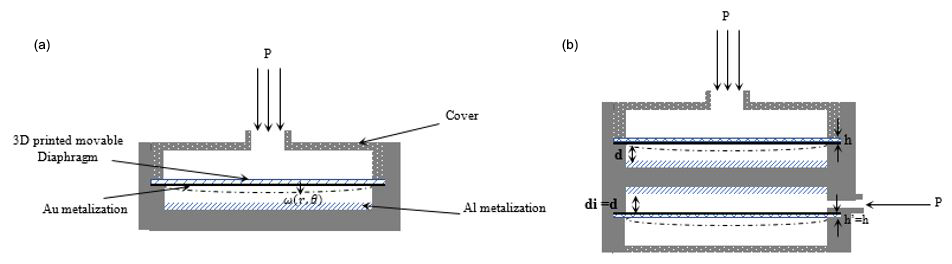
Figure 1Design of the structures of the two studied pressure sensors. (a) Structure A: sensor with C0 fixed. (b) Structure B: sensor with C0 variable.
To improve linearity of the capacitive pressure sensors, several solutions have been proposed in the literature. Among the solutions that have been suggested for modifying the structure of the movable diaphragm is to add a boss or replace the flat structure with a corrugated one (Eswaran and Malarvizhi, 2012; Huang and Zhang, 2014; Jerman, 1990; Li et al., 2018; Sandmaier, 1991; Yu et al., 2013). Other solutions focused on improving the sensitivity as well through combining the change of the movable plate structure with a general modification of the sensor structure (Chitra and Ramakrishnan, 2014; Ettouhami et al., 2004; Zhang et al., 2011) or were based on the principle of the “touch mode” in which the two parallel plates insulated by a nonconductive material touch each other starting from a pressure value called contact pressure (Han and Shannon, 2009; Ko and Wang, 1999; Wang and Ko, 1999). For most of the above solutions, the improvement of linearity is done to the detriment of sensitivity. Furthermore, these works only dealt with the case of small deflections caused by a maximum displacement of the movable diaphragm center, under the applied pressure largely inferior to its thickness.
3D printing has recently gained increasing interest as a possible new manufacturing process of sensors, especially for applications for which cost reduction may be of greater interest than miniaturization. It allows the production of complex 3D parts directly from computer-aided design (CAD) files. This allows rapid prototyping of high-quality products at an affordable cost (Gibson et al., 2015).
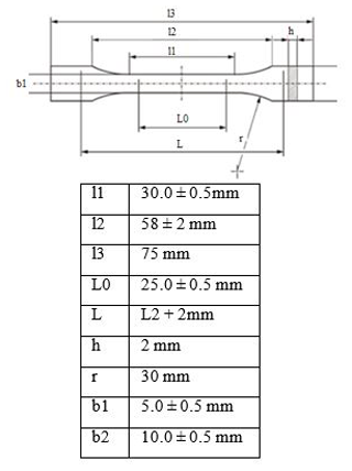
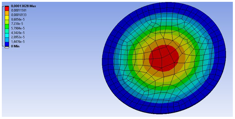
Figure 3Finite element simulation of the printed membrane, showing a maximum deflection at the center equal to 130 µm at 9 KPa.
Materials that can be currently used for 3D-printed pressure sensors are varied. In fact the different capacitive pressure sensors or capacitors reported in the literature have been manufactured using conductive materials (steel, copper, etc.) (Faller et al., 2018; Shemelya et al., 2013; Zhao et al., 2014), or thermoplastic materials whereby metallization is used to provide surface conductivity (Tuna et al., 2017; Zega et al., 2018).
In this work, the 3D-printed relative pressure sensor is manufactured using polylactic acid (PLA) as the manufacturing material. The elements intended to present the capacitive sensor armatures were then coated with conductive materials to ensure the surface conductivity necessary to obtain a capacitive reading. Due to the constraints related to the resolution of the machines used and the mechanical properties of the thermoplastic materials, we could not achieve very small plates' separation compared to the diaphragm thickness, which leads us to a case study of large deflections. Solutions based on modifying the membrane by adding a boss are no longer appropriate in this case study. Therefore we have adopted the structure proposed by Ettouhami et al. ( 2004) in which a sensor composed of two capacitors, the corresponding capacitances of which change simultaneously in opposite senses (difference of capacitances becomes larger). Results of the simulation showed that such a structure improves linearity and sensitivity while keeping the movable diaphragm flat.
On the basis of the structure proposed by Ettouhami et al. (2004) our work consists in studying feasibility through simulation and fabrication of the capacitive sensor using 3D printing technology and testing the linearity and the sensitivity in the case of large deflections.
In our work, we limited ourselves to test the sensor in the pressure range of [0, 9] KPa. Such a range is appropriate for educational purposes for practical teaching and computer-aided design experimentations (Nonnon, 1998).
In this article we describe the sensor dimensioning and the steps of the process of fabrication in two cases: (1) C0, the zero-pressure capacitance, is fixed and (2) C0 is variable. We compare the performances obtained for both the simulated proposed structure and the fabricated one.
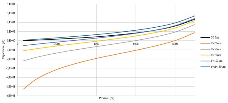
Figure 4Sensor response for different di values compared to the response of the traditional design for which C0 is fixed.
The proposed design is composed of two parallel circular plates. A thin diaphragm called the top plate forms the movable diaphragm of a parallel plates' capacitor. A thick layer called the bottom plate forms the second part of the sensor as shown in Fig. 1a.
To ensure the surface conductivity necessary for the capacitive structure of the pressure sensor, the bottom plate is covered with Al sheet, while the top plate is covered with Au using a sputtering process. The perfect flush mounting of the diaphragm is ensured by a third part called the “cover”, as shown in Fig. 1.
When pressure is applied, the top plate deflects and produces capacitance variations, which can be sensed and calibrated to the real pressure, using the acquisition board and a calibrated pressure sensor.
The capacitance variation in the case of circular plates is expressed by the following equation (Ko et al., 1982):
where C is the capacitance corresponding to the applied pressure P, C0 is the zero-pressure capacitance, R is the diaphragm radius, r is the (radial) distance between the location where the deflection is evaluated and the plate center, ε is the dielectric constant of the dielectric between the plates (in our case the air), d is the zero-pressure plates' separation, and is the function that models the deflection of the top plate.

The study of the sensor response requires the determination of the deflection of the movable plate as a function of the applied pressure. The thin plate theory (Timoshenko et al., 1959) is used and is appropriate for deflections less than 1∕5 of the movable plate thickness. The thick plate theory (Timoshenko et al., 1959) is used for deflections up to 3 times the diaphragm thickness.
For a circular plate with clamped edges, the deflection is zero at its edges. These boundary conditions allow the governing differential equations to be solved for the bending of the movable plate. This allows the diaphragm deflection to be determined at each point of the diaphragm.
Hence, according to Timoshenko et al. (1959) and Eaton et al. (1999),
where f denotes the deflection at the top plate center, R is the plate radius, and r is the distance (radial) between the location where the deflection is evaluated and the plate center. The deflection at the top plate center is obtained using the Ansys simulation tool.
This kind of sensor is known for its nonlinearity. In their work, Ettouhami et al. (2004) proposed a solution in which the zero-pressure capacitance C0 varies as a function of pressure but in the opposite sense of C (Fig. 1).
Hence the capacitance variation for this model is deduced from Eqs. (1) and (2):
where di is the zero-pressure plates' separation for C0.
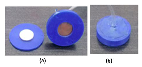
Figure 53D-printed pictures of the sensor: (a) different parts of the sensor and (b) the assembled sensor.

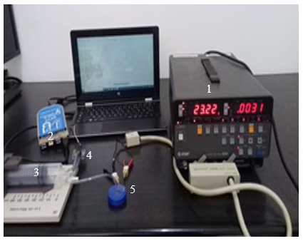
Figure 7Experimental setting. (1) LCZ meter, (2) MicroLabExAO board, (3) syringe pump, (4) differential pressure sensor MPXV7025DP, and (5) fabricated pressure sensor.
Before printing the designs in Fig. 1, a crucial step consists of determining the mechanical properties of the material used, since according to Dizon et al. (2018), Lay et al. (2019), and Reppel and Weinberg (2018), these properties change after printing. For this reason, specimens were printed in conformity to DIN EN ISO 527-2.
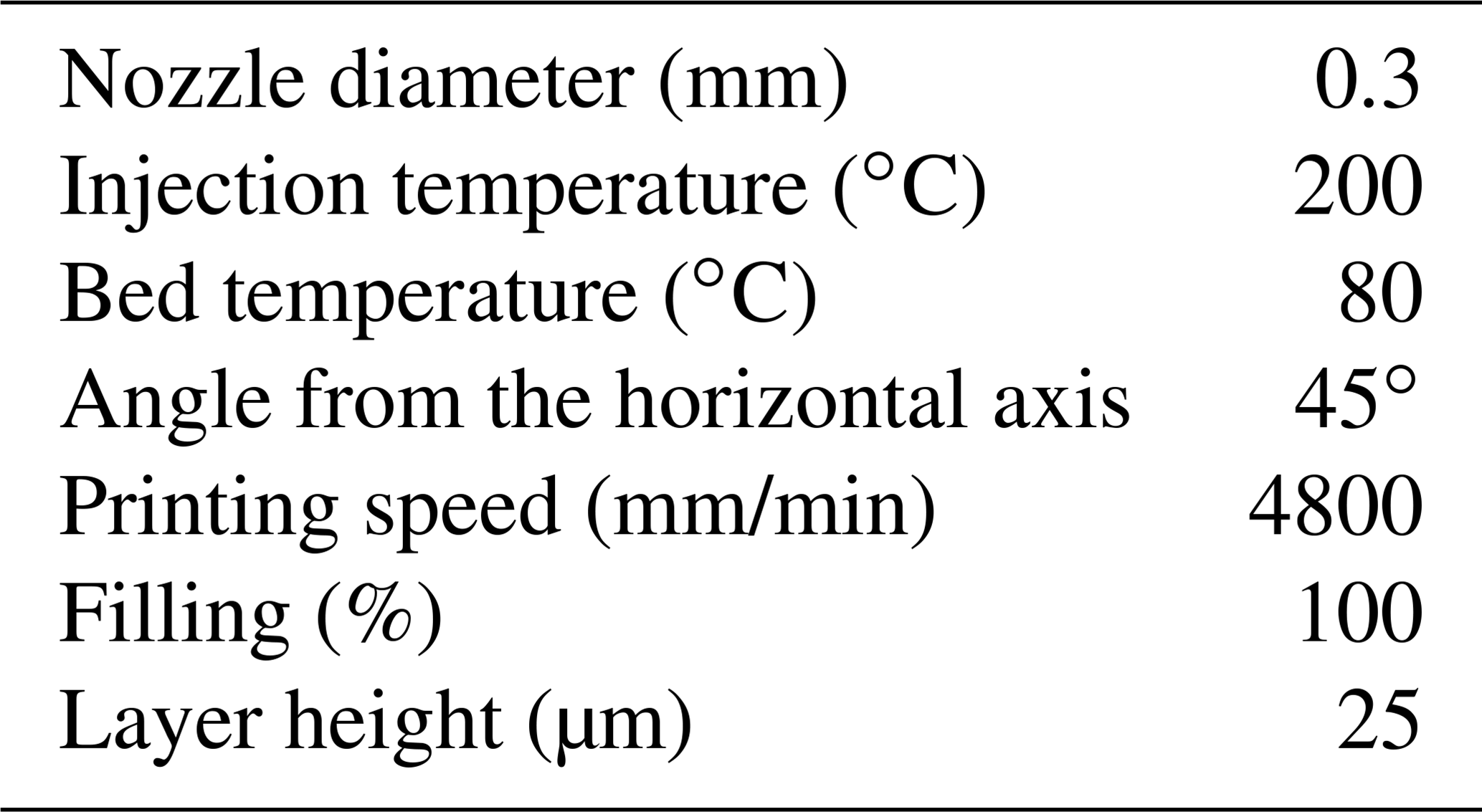
The printing parameters with the most impact on the mechanical properties are mainly the angle, the injection temperature, the layer thickness, and the filling ratio.
The printing parameters are listed in Table 1, and the dimensions of the specimens are given in Fig. 2.
To determine the mechanical properties of the material used, experimental tests were carried out at a speed of 5 mm/min on a universal testing machine (H10KT Tinius), and the results are presented in Table 2.
3.1 Design characteristics of the structure with C0 fixed
The goal here is to increase the sensitivity of the sensor through an adequate choice of the dimensions as follows.
- a.
Thickness of the movable plate. The movable plate is designed exploiting the resolution limits of the printing process. The minimum thickness value allowed by the 3D printer used was 25 µm. After testing the permeability of the membranes for different thickness values, we set the thickness layer to 200 µm.
- b.
Radius. Simulations of the diaphragm behavior with different values of the radius have shown that for R less than 8 mm, the displacement of the diaphragm center under the maximum pressure is much lower than the machine resolution (25 µm). For this reason we have set R=8 mm.
- c.
Zero-pressure plates' separation. After setting the values of R and h, finite element method (FEM) simulations of the diaphragm behavior were carried out using Ansys software to determine its displacement under the maximal pressure.
A maximum pressure of 9 KPa applied at the movable plate center resulted in a maximum deflection of 130 µm as shown in Fig. 3. Therefore, the zero-plate separation set to 150 µm appeared to be a suitable choice considering the 3D printing equipment and limitations.
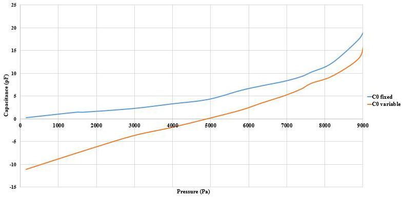
Figure 8Responses obtained of the 3D-printed capacitive sensors at ambient temperature. The blue curve corresponds to the response of the sensor with C0 fixed (structure A), and the orange one corresponds to the sensor with C0 variable (structure B).

Figure 9Responses obtained of the 3D-printed capacitive sensors at ambient temperature. (a) Responses of the sensor with C0 fixed; the orange curve corresponds to the practical response, while the blue one corresponds to the theoretical results. (b) Responses of the sensor with C0 variable; the orange curve corresponds to the practical response, while the blue one corresponds to the theoretical results.
3.2 Design characteristics for the structure with variable C0
In this case we consider the structure consisting of two cells (Fig. 1b). The role of the second cell is to reduce the nonlinearity of the sensor as well as to increase its sensitivity. These performance parameters depend on the value of the plates distance separation of the second cell (referred to as di), Therefore, for designing the sensor, we maintained the same values of h and R determined in Sect. 2 for both cells, then, using Eq. (3), we simulated the behavior of the sensor versus pressure. To determine the best choice for the plates' separation distance, Fig. 4 shows the response of the sensor versus the pressure for values of the plate separation distance varying from 25 µm up to 150 µm. In addition, we plotted in the same graph the response of the structure with the zero-pressure capacitance (C0) fixed to compare the nonlinearity offered in both structures. The curves show that nonlinearity is significantly improved, namely for the plate separation distance of 75 µm within the range [0, 8000] Pa. Nonetheless, for lower values of the distance, the nonlinearity revealed in the range [0, 2000] Pa declines due to the nonlinearity of the second cell.
Furthermore, sensitivity and nonlinearity parameters were calculated for both structures using the formula as follows:
where C(P) denotes the regression polynomial of the capacitance and CL(P) is a linear function.
Table 3Sensitivity and nonlinearity according to the considered pressure measuring range, for di=75 µm.
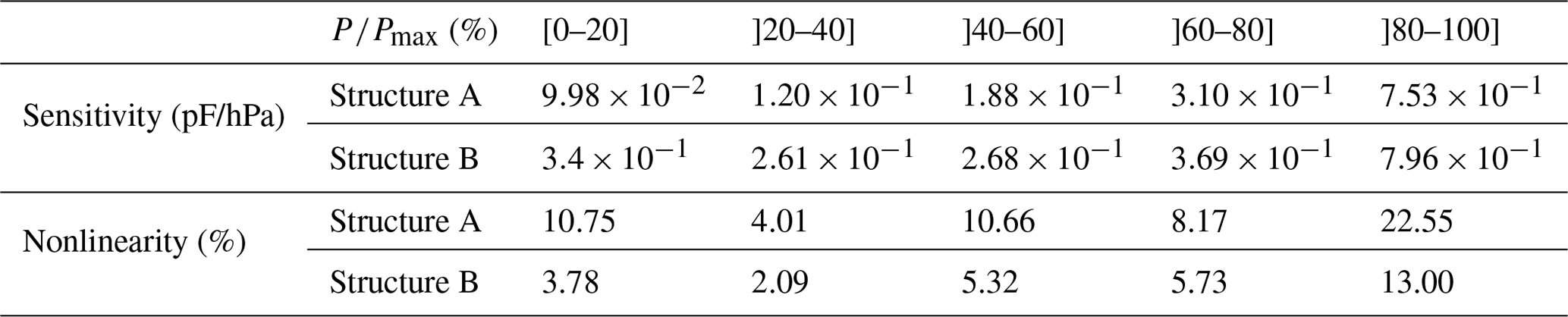
As shown in Table 3, the sensitivity has been improved with the use of the proposed model compared to the traditional one in all the pressure ranges. The nonlinearity of the sensor has also been improved in all pressure range intervals; in addition it remains significant in the range [95 %, 100 %] which may be linked to the important contribution of the movable diaphragm central part compared to that of its edges.
4.1 Manufacturing process
The designs in Fig. 1 were drawn using CATIA modeling software. They were first printed using polylactic acid (PLA) as the manufacturing material, by means of the Volumic 3D 3D printer based on fused deposing modeling printing technology. The printing parameters were those summarized in Table 2.
As a second step, to establish the electrical connections and provide the conductive surface, the top plate was coated with 22 nm Au using a sputtering process, while the bottom plate was covered with an Al sheet to reduce the cost of its fabrication.
To create an electrical connection to the sensor, copper wires were attached to the sensor plates using silver epoxy. The manufactured capacitive sensor is shown in Fig. 5.
4.2 Sensor characterization
Characterization of the manufactured sensors was performed according to the experimental setting as shown in Figs. 6 and 7. The LCZ meter NF2345 was used to measure the capacitance variation, while the MicroLabExAO acquisition board was used to read the value of the applied pressure (Fig. 6).
The LCZ meter is calibrated using the open–short circuit correction to eliminate the bias impedance of the electrode interface. Capacitance is measured with a frequency of 100 KHz and a voltage of 1.0 V.
As shown in Figs. 6 and 7, a syringe pump was connected by means of a T connector to the manufactured pressure sensor and a differential pressure sensor MPXV7025DP. An external pressure in the range of [0, 9] KPa was then applied to the pressure sensors.
Figure 8 shows the results obtained at room temperature with the two manufactured pressure sensors.
The behavior of the capacitances obtained through simulation was compared to that obtained with the fabricated structures as shown in Fig. 9a for the case in which the zero-pressure capacitance C0 is fixed and in Fig. 9b for the case in which C0 is variable.
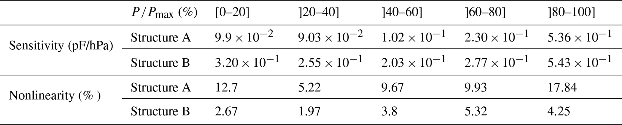
The difference between experimental and theoretical results is due to incertitude in the zero-pressure distance and the plate thickness. Consequently, the fabricated sensors show less sensitivity and nonlinearity compared to the theoretical performances as revealed in Table 4.
In this paper, we presented the design and the characterization of relative pressure sensors fabricated using 3D printing technology and tested at room temperature in the pressure range [0, 9] KPa. The thermoplastic materials used with this technology lead us to a case of large deflections. Such a situation rarely studied in the literature has the disadvantage of increasing the nonlinearity of the pressure sensor.
The proposed work aimed at improving the nonlinearity and the sensitivity of a structure composed of two parallel circular movable diaphragms. In both the simulated and the fabricated models, in the comparison with the traditional structure in which the zero-pressure capacitance is fixed, the proposed sensor showed significant improvement of the nonlinearity as well as the sensitivity. However, the nonlinearity remains higher than 1% due to the high contribution of the mobile diaphragm's central part compared to its edges.
The studied designs were drawn with CATIA software and printed by means of a 3D printer based on fused deposing modeling, using polylactic acid (PLA) as the manufacturing material.
Data will be made available on request.
SA designed and conducted the simulation and experimental investigations. MG and FR supervised the research. All authors discussed and proofread the manuscript.
The authors declare that they have no conflict of interest.
The authors would like to thank the Ministry of National Education, Higher Education, Staff Training, and Scientific Research (MESRSFC) and the National Center of Scientific and Technical Research (CNRST), Morocco, for providing financial assistance for this research work.
This paper was edited by Nam-Trung Nguyen and reviewed by two anonymous referees.
Aldaoud, A., Laurenson, C., Rivet, F., Yuce, M. R., and Redoute, J. M. Design of a miniaturized wireless blood pressure sensing interface using capacitive coupling, IEEE/ASME Transactions on Mechatronics, 20, 487–491, https://doi.org/10.1109/TMECH.2014.2322614, 2015.
Bae, B., Flachsbart, B. R., Park, K., and Shannon, M. A.: Design optimization of a piezoresistive pressure sensor considering the output signal-to-noise ratio, J. Micromech. Microeng, 14, 1597–1607, https://doi.org/10.1088/0960-1317/14/12/001, 2004.
Chitra, L. and Ramakrishnan, V.: A novel design of capacitive MEMS pressure sensor for lubricating system, Proceedings – NCET NRES EM 2014: 2nd IEEE National Conference on Emerging Trends in New and Renewable Energy Sources and Energy Management, Chennai, India, 16–17 December 2014, 204–208, 2014.
Dizon, J. R. C., Espera, A. H., Chen, Q., and Advincula, R. C.: Mechanical characterization of 3D-printed polymers, Additive Manufacturing, 20, 44–67, https://doi.org/10.1016/j.addma.2017.12.002, 2018.
Eaton, W. P., Bitsie, F., Smith, J. H., and Plummer, D. W.: A New Analytical Solution for Diaphragm Deflection and its Application to a Surface-Micromachined Pressure Sensor, Technical Proceedings of the 1999 International Conference on Modelling and Simulations of Microsystems, MSM 99, San Juan, Puerto Rico, USA, 19–21 April 1999, 640–643, 1999.
Eswaran, P. and Malarvizhi, S.: Sensitivity analysis on MEMS capacitive differential pressure sensor with bossed diaphragm membrane, 2012 International Conference on Devices, Circuits and Systems, Coimbatore, India, 15–16 March 2012, 704–707, 2012.
Ettouhami, A., Zahid, N., and Elbelkacemi, M.: A novel capacitive pressure sensor structure with high sensitivity and quasi-linear response, CR. Mecanique, 332, 141–146, https://doi.org/10.1016/j.crme.2003.10.001, 2004.
Faller, L. M., Granig, W., Krivec, M., Abram, A., and Zangl, H.: Rapid prototyping of force/pressure sensors using 3D- and inkjet-printing, J. Micromech. Microeng, 28, 104002, https://doi.org/10.1088/1361-6439/aaadf4, 2018.
Gibson, I., Rosen, D., and Stucker, B.: Additive manufacturing technologies: 3D printing, rapid prototyping, and direct digital manufacturing, second edition, Springer, New York, Heidelberg, Dordrecht London, 1–498, https://doi.org/10.1007/978-1-4939-2113-3, 2015.
Han, J. and Shannon, M. A.: Smooth contact capacitive pressure sensors in touch- and peeling-mode operation, IEEE. Sens. J, 9, 199–206, https://doi.org/10.1109/JSEN.2008.2011090, 2009.
Huang, X. and Zhang, D.: A high sensitivity and high linearity pressure sensor based on a peninsula-structured diaphragm for low-pressure ranges, Sensor Actuat. A-Phys., 216, 176–189, https://doi.org/10.1016/j.sna.2014.05.031, 2014.
Javed, Y., Mansoor, M., and Shah, I. A.: A review of principles of MEMS pressure sensing with its aerospace applications, Sensor Rev., 39, 652–664, https://doi.org/10.1108/SR-06-2018-0135, 2019.
Jerman, J. H.: The fabrication and use of micromachined corrugated silicon diaphragms, Sensor Actuat. A-Phys., 23, 988–992, https://doi.org/10.1016/0924-4247(90)87074-S, 1990.
Ko, W. H. and Wang, Q.: Touch mode capacitive pressure sensors, Sensor Actuat. A-Phys., 75, 242–251, https://doi.org/10.1016/S0924-4247(99)00069-2, 1999.
Ko, W. H., Bao, M. H., and Hong, Y. D.: A High-Sensitivity Integrated-Circuit Capacitive Pressure Transducer, IEEE T. Electron Dev., 29, 48–56, https://doi.org/10.1109/T-ED.1982.20657, 1982.
Kumar, S. S. and Pant, B. D.: Design principles and considerations for the “ideal” silicon piezoresistive pressure sensor: A focused review, Microsyst. Technol., 20, 1213–1247, https://doi.org/10.1007/s00542-014-2215-7, 2014.
Lay, M., Thajudin, N. L. N., Hamid, Z. A. A., Rusli, A., Abdullah, M. K., and Shuib, R. K.: Comparison of physical and mechanical properties of PLA, ABS and nylon 6 fabricated using fused deposition modeling and injection molding, Compos. Part B: Eng., 176, 107341, https://doi.org/10.1016/j.compositesb.2019.107341, 2019.
Lee, Y. S. and Wise, K. D.: A Batch-Fabricated Silicon Capacitive Pressure Transducer With Low Temperature Sensitivity, IEEE. Trans. Electron, 29, 42–48, https://doi.org/10.1109/T-ED.1982.20656, 1982.
Li, G., Li, D., Cheng, Y., Sun, W., Han, X., and Wang, C.: Design of pressure-sensing diaphragm for MEMS capacitance diaphragm gauge considering size effect, AIP Adv., 8, 035120, https://doi.org/10.1063/1.5021374, 2018.
Martini, E., Fiumalbi, T., Dell'agnello, F., Ivanić, Z., Munih, M., Vitiello, N., and Crea, S.: Pressure-sensitive insoles for real-time gait-related applications, Sensors, 20, 14448, https://doi.org/10.3390/s20051448, 2020.
Menini, P.: Faisabilité d'un capteur de pression capacitif miniature sur silicium, Ph.D. Thesis, Micro et nanotechnologies/Microélectronique, University Paul Sabatier – Toulouse III, Toulouse, France, 234 pp., 1998.
Muhammad, H. B., Oddo, C. M., Beccai, L., Recchiuto, C., Anthony, C. J., Adams, M. J., Carrozza, M. C., Hukins, D. W. L., and Ward, M. C. L.: Development of a bioinspired MEMS based capacitive tactile sensor for a robotic finger, Sensor Actuat. A-Phys., 165, 221–229, https://doi.org/10.1016/j.sna.2010.10.025, 2011.
Nonnon, P.: Intégration du réel et du virtuel en science expérimentale, 8èmes Journées Informatique et Pédagogie des Sciences Physiques – Montpellier, INRP Publications, Paris, France, 1998.
Palasagaram, J. N. and Ramadoss, R.: MEMS-capacitive pressure sensor fabricated using printed-circuit-processing techniques, IEEE. Sens. J, 6, 1374–1375, https://doi.org/10.1109/JSEN.2006.884430, 2006.
Reppel, T. and Weinberg, K.: Experimental determination of elastic and rupture properties of printed Ninjaflex, Technische Mechanik, 38, 104–112, https://doi.org/10.24352/UB.OVGU-2018-010, 2018.
Rosengren, L., Söderkvist, J., and Smith, L.: Micromachined sensor structures with linear capacitive response, Sensor Actuat. A-Phys., 31, 200–205, https://doi.org/10.1016/0924-4247(92)80104-B, 1992.
Ruth, S. R. A., Beker, L., Tran, H., Feig, V. R., Matsuhisa, N., and Bao, Z.: Rational Design of Capacitive Pressure Sensors Based on Pyramidal Microstructures for Specialized Monitoring of Biosignals, Adv. Funct. Mater., 30, 1903100, https://doi.org/10.1002/adfm.201903100, 2019.
Sandmaier, H.: Non-linear analytical modelling of bossed diaphragms for pressure sensors, Sensor Actuat. A-Phys., 27, 815–819, https://doi.org/10.1016/0924-4247(91)87092-H, 1991.
Shemelya, C., Cedillos, F., Aguilera, E., Maestas, E., Ramos, J., Espalin, D., Muse, D., Wicker, R., and MacDonald, E.: 3D printed capacitive sensors, Proceedings of IEEE Sensors, 3, 0–3, https://doi.org/10.1109/ICSENS.2013.6688247, 2013.
Song, P., Si, C., Zhang, M., Zhao, Y., He, Y., Liu, W., and Wang, X.: A novel piezoresistive MEMS pressure sensors based on temporary bonding technology, Sensors, 20, 337, https://doi.org/10.3390/s20020337, 2020.
Sparks, D.: MEMS pressure and flow sensors for automotive engine management and aerospace applications, in : MEMS for automotive and aerospace applications, Woodhead Publishing Limited, Shenyang, Liaoning, China, 78–105, https://doi.org/10.1533/9780857096487.1.78, 2013.
Timoshenko, S. and Woinowsky-Krieger, S.: Theory of Plates and Shells, second edition, 591 pp., McGraw-Hill, New York, 1959.
Tuna, A., Erden, O. K., Gokdel, Y. D., and Sarioglu, B.: 3D printed capacitive pressure sensor with corrugated surface. PRIME 2017 – 13th Conference on PhD Research in Microelectronics and Electronics, Proceedings, 1, Naxos-Taormina, Italy, 12–15 June 2017, 149–152, 2017.
Wang, Q. and Ko, W. H.: Modeling of touch mode capacitive sensors and diaphragms, Sensor Actuat. A-Phys., 75, 230–241, https://doi.org/10.1016/S0924-4247(99)00068-0, 1999.
Yu, Z., Zhao, Y., Sun, L., Tian, B., and Jiang, Z.: Incorporation of beams into bossed diaphragm for a high sensitivity and overload micro pressure sensor, Rev. Sci. Instrum., 84, 015004, https://doi.org/10.1063/1.4775603, 2013.
Zega, V., Credi, C., Bernasconi, R., Langfelder, G., Magagnin, L., Levi, M., and Corigliano, A.: The first 3-D-printed z-axis accelerometers with differential capacitive sensing, IEEE. Sens. J, 18, 53–60, https://doi.org/10.1109/JSEN.2017.2768299, 2018.
Zhang, Y., Howver, R., Gogoi, B., and Yazdi, N.: A high-sensitive ultra-thin MEMS capacitive pressure sensor, 16th International Solid-State Sensors, Actuators and Microsystems Conference, TRANSDUCERS'11, Beijing, China, 5–9 June 2011, 112–115, 2011.
Zhao, C., Wang, C., Gorkin, R., Beirne, S., Shu, K., and Wallace, G. G.: Three dimensional (3D) printed electrodes for interdigitated supercapacitors, Electrochem. Commun., 41, 20–23, https://doi.org/10.1016/j.elecom.2014.01.013, 2014.