the Creative Commons Attribution 4.0 License.
the Creative Commons Attribution 4.0 License.
Development of a rotating-coil scanner for superconducting accelerator magnets
Lucio Fiscarelli
Stephan Russenschuck
Kay Hameyer
The High-Luminosity upgrade project for the Large Hadron Collider (HL-LHC) at CERN (Conseil Européen pour la Recherche Nucléaire) will require new superconducting magnets for the insertion regions. Among these magnets, the new triplet quadrupoles, based on Nb3Sn technology, require magnetic-field measurements of a high precision in the field angle and multipole field errors. In this paper, we present a scanning system based on a rotating-coil magnetometer and its transport system, including the design of the mechanical structure and the induction coils based on printed-circuit-board (PCB) technology. The system and its components are cross-calibrated with other field transducers, such as stretched-wire systems, and their measurement precision is established in a measurement campaign of 2 m long reference quadrupoles.
- Article
(4239 KB) - Full-text XML
- BibTeX
- EndNote
The High-Luminosity upgrade of the Large Hadron Collider (HL-LHC) (Apollinari et al., 2017) requires replacing the superconducting magnets in the insertion regions. These magnets have a variety of aperture sizes, lengths and pole numbers. The beam optics of the HL-LHC poses strict requirements for their field quality. Therefore, the magnets must be measured with even more stringent requirements with respect to the state of the art, both locally and integrated over their entire length of up to 10 m.
To meet these requirements, the superconducting quadrupole magnets have to be measured using both rotating-coil magnetometers (Davies, 1992) and stretched-wire systems (DiMarco et al., 2000). This substantially increases the measurement time and resources. It is therefore advantageous to develop a magnetometer that allows for measuring all required quantities simultaneously.
Harmonic fields and rotating-coil magnetometers
A 2-D magnetic field in a domain that is free of current and magnetized material (such as the bore of accelerator magnets) can be described by a complex-valued harmonic field expansion.
where r0 is the reference radius and Bn and An are called the normal and skew harmonic coefficients, or in short, field multipoles. In practice, the nth coefficient corresponds to a field generated by a magnet with n pole pairs, e.g., n=2 for a quadrupole magnet.
In the case of accelerator magnets, the field along the magnet length can be integrated and shown to satisfy the 2-D Laplace equation. The same applies to the field integrated along the length of an induction coil, with the constraint that the ends of the coil must extend to the region that is free of axial field components. Otherwise, the measurement results do not correspond to the 2-D mathematical model but must be treated with the theory of pseudo-multipoles (Arpaia et al., 2019).
The rotating-coil measurement principle is especially suited to characterize the fields described as in Eq. (1). This is due to the fast and robust analysis of the output signals. According to Faraday's law,
using the principal coil arrangement in the shaft and the geometric relations shown in Fig. 1, it is possible to calculate the magnetic flux intercepted by the induction coil. Starting from the complex field representation (Eq. 1) and writing , the flux intercepted by the induction coil spanning from z1 to z2 can be calculated with . Because of
the flux can be expressed as
where l is the coil length, N is the number of turns and (at the reference radius r0). The Sn are complex-valued sensitivity factors given by
Radial coils, as shown in Fig. 1a, intercept the azimuthal component of the magnetic flux density. For , inner radius r1 and outer radius r2 the are zero, and we obtain
The is calculated using the geometry of the coils and its arrangement in the probe. The field multipoles can be calculated from the measurements by
where is the sensitivity factor (defined to be independent of the reference radius) and ψn is complex coefficient of the Fourier transform of the acquired integrated voltage. The harmonic content of the field is used as one of the quality measures. Generally, a field of an acceptable quality is defined to have at most a few hundred ppm of multipole coefficients.
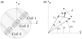
Figure 1(a) Radial coil array. (b) Naming convention for angles and radii of a single-wire loop (Russenschuck, 2010).
In practice, magnetic measurements affected by mechanical imperfections and signal noise require additional measures and post-processing steps to achieve the specified accuracy. First off, for the integration of voltage it is necessary to keep exact track of the timing. This is challenging due to the instabilities in shaft rotation caused by the motor and bearings. The established solution to that problem is the use of digital integrators triggered by an angular encoder coupled with the shaft. The voltage between two triggers is integrated, yielding a measure of the incremental flux linkage between the two rotor positions. Mathematically this corresponds to a reparametrization of the signal with respect to the rotation angle.
Multiple coils in the probe can be connected in an appropriate configuration to provide compensation for the main-field components (Schmüser, 1992) – in our case the quadrupole and dipole field components. This allows to amplify the compensated signal, thus increasing the signal-to-noise ratio (SNR) for the higher-order field harmonics. Moreover, compensation reduces the impact of mechanical vibrations and displacements, as all connected coils are subject to the same modes of vibration.
Finally, to correct the misalignment of the measurement coils with the magnetic axis, a so-called feed-down correction is applied (Russenschuck, 2010). In the case of a centered quadrupole measurement, the dipole component will vanish, except if the coil is decentered with respect to the magnetic axis. This misalignment can be calculated and corrected by translating the reference frame of the sensor to the magnet axis. This yields the centered field harmonic coefficients as well as the position of the magnetic field center in the local sensor coordinates.
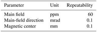
The requirements for the measurement system are based on the HL-LHC insertion region layout resulting in the accuracy specifications given in Table 1.
Table 1The target accuracy for LHC insertion region quadrupole measurements (Apollinari et al., 2017).
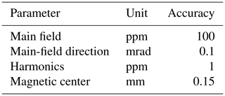
All quantities must be achieved both locally and integrated along the entire length of the magnet. In this way, the magnetic measurements allow to intercept manufacturing errors at an early state in the production process.
The two types of systems commonly used for magnetic measurements of long accelerator magnets are rotating-coil magnetometers and stretched-wire systems. A summary of the currently achievable measurement accuracy for those systems is given in Table 2.
Table 2Existing systems accuracy (Bottura et al., 2006; DiMarco et al., 2013, 2000; Perez et al., 2006).
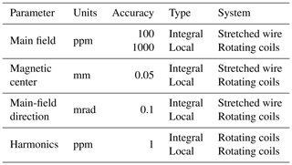
The accuracy for the integral field center and field direction measurements has been obtained with a single-stretched-wire system as used for the LHC main quadrupoles (DiMarco et al., 2000). These magnets posed challenges similar to the ones to be measured in the LHC upgrade project. The expected accuracy for the field harmonics are based on the probes developed by the Fermi National Accelerator Laboratory (FNAL) and Lawrence Berkeley National Laboratory (LBNL) for the LHC Accelerator Research Program (LARP) described in DiMarco et al. (2013). These probes are designed for measuring a high-gradient quadrupole magnet and are based on a principle similar to the presented system, with the use of induction coils produced with printed-circuit-board (PCB) technology. The accuracy of the other parameters retrieved by rotating-coil systems are based on the performance of the legacy QIMM (Quadrupole Industrial Magnetic Measurement) and DIMM (Dipole Industrial Magnetic Measurement) systems, used for LHC dipole and quadrupole measurements at ambient temperatures (Perez et al., 2006).
It can be observed that even though for most parameters a system exists that allows for a measurement with the required accuracy, it is necessary to use at least two complementary systems to measure and derive all required data. Given the considerable time and effort for each measurement, a new system had to be developed that is able to measure all aforementioned quantities simultaneously.
Additionally, as the new magnets will have multiple different lengths and apertures, the system needs to be easily adaptable. The size and radius of the induction coils have an influence on the amplitude of the acquired signal and thus on the signal-to-noise ratio.
The best approach was to design a new rotating-coil system, which is able to provide all required values locally, by including a displacement system that allows for the longitudinal scanning of the magnet bore. After scanning the entire magnet bore, the system can provide the integral values as well by combining the local measurement results.
By comparing the specification with the designs of existing rotating-coil scanners, like the QIMM (Perez et al., 2006) or the Ferret (FERmilab Rotating-coil Encapsulated Tesla-probe) (DiMarco et al., 2013), we derived the main design concepts:
-
construction adaptable to magnet apertures ranging from 90 to 150 mm,
-
3-D printing for complicated structural parts,
-
built-in encoder and level meter,
-
PCB-based induction coils,
-
open end for mounting retroreflectors for the use of a laser tracker,
-
and a transport system with extension rods.
The placement of the encoder and the level meter close to the induction coils is necessary to precisely track their angular position that in turn enables the accurate measurement of the angle of the magnetic field. In order to relate the magnetic axis measurement (given in the probe coordinates) to the magnet reference, one end of the scanner must be open to provide a line of sight to the laser tracker. During the rotation of the magnetometer, the tracker follows the retroreflectors mounted on the shaft. By fitting a circle to the measured points, it is possible to find the mechanical rotation axis. The offset of the magnetic field axis from the rotation axis is given by the feed-down correction, as mentioned in Sect. 1. The precise longitudinal positioning is realized by the use of extension rods that also transmit the rotation from a motor placed outside the magnet.
The base mechanical structure of the probe was fabricated using 3-D printing technology due to its complicated shape and because the prototype version was designed to accommodate multiple solutions for testing. The two main features to be tested were the positioning of the level meter as well as the guiding of the probe in the magnet aperture. In the first tested variant, the level meter was mounted to the base of the probe, which was held in position during the measurement using the stabilizing wheels shown in Fig. 2. The main goal of the wheels is to facilitate longitudinal displacements while retaining the angular position of the base during the coil rotation. The probe is equipped with three wheels mounted at the end of the base structure. They are inserted into a fitting slot and fastened with screws.
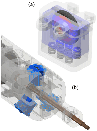
Figure 2Rendering of the stabilizing wheel (a) and a detail of its mounting in the base of the probe (b). The wheel assemblies are highlighted in blue.
Considering the high positioning accuracy required for the PCB coils and the size limitations for 3-D printing, the support shaft for the PCB board was machined from a fiber-glass epoxy composite. The support shaft was designed to allow the mounting of differently sized PCBs without major modifications, in particular, without disassembling the base structure. Moreover, the shaft is easy to machine and modify thanks to its parametric design. This is in line with the adaptability requirement; a single probe can be used for measuring magnets of different bore radii. The final design of the first prototype is shown in Fig. 3.
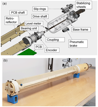
Figure 3First prototype measurement system. (a) View of the probe base structure. (b) The assembled system.

Figure 4The PCB board containing an array of 10 coils. The top 500 and 100 mm long coils are marked with black and white rectangles, respectively.
The fabricated PCBs (see Fig. 4) are equipped with two sets of five induction coils. The design objective was to maximize the number of turns, without reducing the average measurement radius of the coil below 35 mm, which is derived from the specifications of the measurement accuracy. To balance the cost and complexity of manufacturing, the number of layers in the PCB was limited to 24. The number of turns per layer has been established by taking into account the clearance of 125 µm between the tracks and a copper-track width of 125 µm. We were able to fit 11 turns per layer, which resulted in a total of 264 coil-winding turns, while minimizing the chances for short circuits or track breaks.
The 500 mm long coils were designed to cover the entire length of the magnet end region and provide a high SNR. The smaller, nested coils of 100 mm in length can be used in case a higher longitudinal resolution is required. In the case of induction–coil arrays manufactured with PCB technology, adding the nested coils comes at very little cost both in design and production.
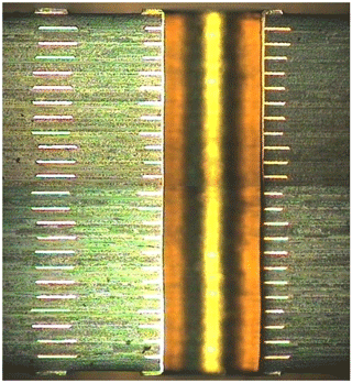
To study the uncertainty in the measurements due to manufacturing tolerances in the PCB production and layer stacking, the “witness tracks” were inspected under a microscope (see Fig. 5).
By measuring the positions of the tracks, we established the accuracy of the layer positioning to be within ±30 µm. Using the CERN (Conseil Européen pour la Recherche Nucléaire) field computation program ROXIE (Routine for the Optimization of magnet X-sections, Inverse field calculation and coil End) (Russenschuck, 2010), we calculated the sensitivity factors of the coil with random errors of layer placement in this range of tolerance. The results over 500 iterations show that for the coefficients of lower orders, the standard deviation in the sensitivity factors is negligible, while for the coefficients of higher orders (15th and above) the standard deviation can be close to the percent range. This, in turn, would result in a relative error on the order of ppm in the measurement, as the higher-order components in the field rarely exceed 100 ppm.
The limited tolerances of the manufacturing and assembly process require calibration of the coils and shaft assembly.
4.1 Coil calibration
The first step of the calibration is measuring the spanned surface of the PCB coils (Buzio, 2009). Even if one can rely on the optical measurements of the track positions, the calibration step is necessary for verifying the correctness of the coil production and detecting inter-turn shorts that cannot be detected by resistance measurements. The measured surface is used for computing the transfer function between the acquired voltage signal and the magnetic flux intercepted by the induction coil.
The surface of the coil can be calibrated by flipping it upside down in the uniform magnetic field of a reference magnet while integrating the output voltage. The integration yields
where is the average magnetic flux density and A is the surface spanned by the coil. The average surface measured for the three produced PCBs is 1.8734 m2. The measurements must be corrected for the resistance of the coil (2.7 kΩ), as it is not negligible against the resistance of 2 MΩ of the input stage of the integrator. The measured values show very high homogeneity between the coils on one PCB as well as between the boards; the differences are on the order of 10−4 m2.
The relative difference between measurement results and the nominal surface from the PCB design was approximately 0.1 %. The reason for this discrepancy is the shrinking of the PCB during production.
A precise geometric measurement of the reference points on the board (see Fig. 6) provided values to calculate the shrinking factor, assuming homogeneous shrinking of the whole board. The computed area (corrected by the shrinking factor) equal to 1.8727 m2 differs from the measured surfaces on the order of 10−4 m2. These values are very close to the standard deviation of the calibration results that is on the order of 10−5.

Figure 6Comparison of measured and design values for coil reference points. Measured values are in parentheses (in millimeters).
More PCB samples are needed to create proper statistics and identify the important factors for refining the design and fabrication process. The ultimate goal of these efforts is to be able to assume, with high certainty, that the final coil area corresponds to the design within the 10−5 relative tolerance. This would limit the role of the surface calibration to a mere electrical verification of the PCB coils (polarity and inter-turn short). This is especially important for larger PCBs that do not fit into the bore of the available reference magnets.
4.2 Radius calibration
The normal procedure consists of measuring the field with the probe in the center of the magnet and displaced by a known offset, typically 10 mm. Using the feed-down correction and comparing the results to the known displacement, it is possible to determine each coil rotation radius.
The precision of this procedure relies heavily on the displacement precision and mechanical stability. Assuming the positioning accuracy of 10 µm on the total displacement of 10 mm, the resulting calibration accuracy is on the order of 0.1 %, which is insufficient, in particular for the measurement of a quadrupole field that depends linearly on the coil rotation radius. By repeating the calibration step five times, we achieved a repeatability of 0.2 %.
As the calibrated coil surface is in very good agreement with the design values, it should be possible to establish the rotation radius with at least comparable accuracy. Hence, the final coil rotation radius was calculated using the design values and the measured shrinking of the PCB. This radius calculation assumes perfect positioning of the PCB in the rotating shaft center, which is difficult to achieve. However, the exact knowledge of the distance between the coils on the PCB allows us to compensate for the decentering using the so-called gradient coil arrangement. By connecting the two outermost coils with opposite polarities, we obtain a signal that is insensitive to coil positioning errors and of double amplitude, further increasing the SNR.
In fact, acquiring the voltage signal from both outermost coils offers the possibility of an in situ calibration of the coil position in the shaft (DiMarco et al., 2019). By comparing the signals from a single coil to a gradient coil, it is possible to calculate the horizontal and vertical offset of the PCB from the rotation axis. This in turn can be used to improve the accuracy of the harmonics measurement. The key aspect here is the exact knowledge of the coil positioning on the PCB.
4.3 Angular-offset calibration
The angular-offset calibration is a relatively straightforward procedure involving measuring the angle of the magnet from both sides. The angular-offset contribution in the measured angle remains unchanged, while the angle of the magnetic field changes sign. Therefore it is possible to calculate both the angular offset and the true field direction as follows:
where φ1 and φ2 are the field directions measured from both sides of the magnet.
The first validation measurement campaign was conducted in two reference quadrupoles used in the Magnetic Measurement (MM) section at CERN. Figure 7 shows a measurement setup in one of the short magnets.
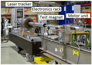
Figure 7Measurement setup with all system components. The probe is inside the tube that goes through the magnet.
Both magnets have been scanned along their entire length, using the laser tracker for longitudinal positioning as well as for tracking the rotation axis. In each position, the coils have been rotated 20 times in both directions to compensate for angular-positioning errors and provide data for uncertainty analysis. The precision of local measurements shown in Table 3 and Fig. 8 is consistent for the different positions in both magnets.
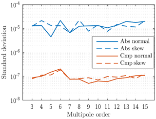
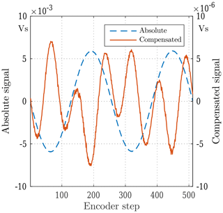
Figure 8The measurement precision of field harmonics of a single position. Abs: absolute. Cmp: compensated.
Figure 8 shows the advantages of the compensation scheme for the main-field components. If the field harmonics are calculated using the signal from a single coil, the precision is at least 100 times worse. The quality of the coil production and positioning can be assessed by comparing the field strength measured by a single coil and the coils connected in a compensation scheme. The resulting proportional factor is commonly called the compensation (or bucking) ratio. As seen from the scale differences in Fig. 9 the achieved bucking ratios for dipole and quadrupole components are on the order of 1000.
The integral values are computed from the local measurement results at all positions along the magnet. The local values have to be multiplied by the induction-coil length and then summed up. Here, two additional factors play an important role: the knowledge of the exact length of the coil and the precise longitudinal positioning, especially in the end regions of the magnet. The measurements have been conducted with both long and short coils several times to evaluate the repeatability of the system. The results are shown in Figs. 10 and 11.
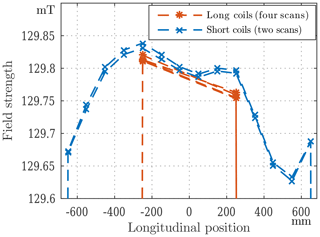
Figure 10Results of repeated scans with both long and short coils. External positions are removed from the plot to emphasize the details in the straight-field region.
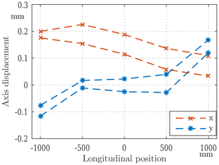
Figure 11Axis measurement results of two scans with long coils. The plot is centered at the average axis measured by a stretched-wire system.
Field scanning revealed that the system mechanics is not precise enough, which results in movements of the base support during the rotation. Due to the compensation, the effect on the field strength and field harmonic measurements is negligible, but it has a noticeable influence on the axis and, especially, on the angle measurement. Since the integral values depend on the longitudinal positioning, the movement of the probe reduces the accuracy of the measured field integral as well.
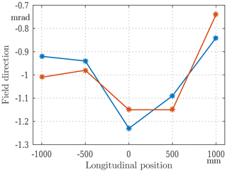
The results of the field direction measurements are shown in Fig. 12. The most prominent issue is the drift between the scans, which indicates a lack of stability in the mounting of the level meter. As described in Sect. 4.3, it would be possible to compensate for the drift by calibrating the angular offset before each measurement. To estimate the viability of that solution, we normalized each scan to its average value to compare the field direction changes along the magnet. This relative field direction profile is then consistent to 0.1 mrad. This method would however complicate the measurement procedure and is affected by the same instability, as it requires removing the probe from the magnet.
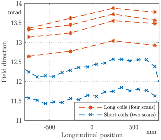
Figure 12Field direction measurement results. First configuration with the level meter separated from the encoder.
The scan results have been compared to a stretched-wire measurement that is the reference for integral values. The integrated gradient is in a good agreement with the wire measurement; the accuracy is at the level of 300 ppm, which is a promising result. The axis is within 0.15 mm from the wire measurement, which needs to be further investigated. Given the high repeatability of local measurements, it should be possible to further improve these values. The presented results have been obtained in controlled and favorable environmental conditions. The reference quadrupole has a relatively high and pure field of approximately 130 mT at the reference radius of 35 mm.
After the first test campaign, we substituted the stabilizing wheels with a pneumatic brake and placed the level meter directly on the encoder. In this way, and by leveling the probe before the measurement, we can rely on the more linear range of the tilt sensor that moves with the encoder. This modification resulted in more stable and precise angle measurements, even without changing the mechanical structure. The accuracy of the field angle measurement has been established to be better than 0.1 mrad (see Fig. 13).
A new rotating-coil magnetometer has been developed and characterized. The results of the measurements already indicate that its performance is at least as good as other existing systems while offering the functionality of those systems combined. A prototype of a long insertion region quadrupole for HL-LHC has been measured and the results have been used as feedback to the magnet development.
The adaptable design of the system and the use of 3-D printing allowed us to easily test multiple configurations of the mechanical structure and induction-coil setup. Some of the encountered mechanical issues have been addressed. While the measurement of the field strength and field harmonics is only slightly affected by mechanical imperfections (mainly due to the compensation scheme), the measurements of the angle and magnetic axis require much higher mechanical precision.
The aim of substituting the stretched-wire system with the integrated measurements of the rotating-coil scanner has thus become feasible.
Raw data underlying the research results are available upon request to the authors.
PR and LF designed the system, conducted the measurements and performed the data analysis. SR was responsible for the supervision and methodology of the project. PR wrote the paper, and it was reviewed and edited by LF, SR and KH.
The authors declare that they have no conflict of interest.
This article is part of the special issue “Sensors and Measurement Systems 2019”. It is a result of the “Sensoren und Messsysteme 2019, 20. ITG-/GMA-Fachtagung”, Nuremberg, Germany, 25–26 June 2019.
The authors would like to thank the Magnetic Measurement section laboratory and workshop staff for their help in assembling and testing the system. We would also like to thank David Giloteaux, Olaf Dunkel and Juan Garcia Perez for helpful suggestions and discussions.
This research has been supported by the Wolfgang Gentner Programme of the German Federal Ministry of Education and Research (grant no. 05E15CHA).
This paper was edited by Martina Gerken and reviewed by two anonymous referees.
Apollinari, G., Béjar Alonso, I., Brüning, O., Fessia, P., Lamont, M., Rossi, L., and Tavian, L.: CERN Yellow Reports: Monographs, Vol 4 (2017): High-Luminosity Large Hadron Collider (HL-LHC) Technical Design Report V. 0.1, https://doi.org/10.23731/CYRM-2017-004, 2017. a, b
Arpaia, P., Caiafa, G., and Russenschuck, S.: A Rotating-Coil Magnetometer for Scanning Transversal Field Harmonics in Accelerator Magnets, Sci. Rep., 9, 1491, https://doi.org/10.1038/s41598-018-37371-3, 2019. a
Bottura, L., Buzio, M., Pauletta, S., and Smirnov, N.: Measurement of magnetic axis in accelerator magnets: critical comparison of methods and instruments, in: Proceedings of the 23rd IEEE Instrumentation and Measurement Technology Conference, 2006, IMTC 2006, IEEE Operations Center, Sorrento, Italy, 24–27 April 2006, 765–770, https://doi.org/10.1109/IMTC.2006.328154, 2006. a
Buzio, M.: Fabrication and calibration of search coils, in: CAS – CERN Accelerator School: Specialised course on Magnets, edited by: Brandt, D., CERN, 387–421, https://doi.org/10.5170/CERN-2010-004, 2009. a
Davies, W. G.: The theory of the measurement of magnetic multipole fields with rotating coil magnetometers, Nucl. Instrum. Meth. A, 311, 399–436, https://doi.org/10.1016/0168-9002(92)90637-J, 1992. a
DiMarco, J., Glass, H., Lamm, M. J., Schlabach, P., Sylvester, C., Tompkins, J. C., and Krzywinski, I.: Field alignment of quadrupole magnets for the LHC interaction regions, IEEE T. Appl. Supercon., 10, 127–130, https://doi.org/10.1109/77.828192, 2000. a, b, c
DiMarco, J., Chlachidze, G., Makulski, A., Orris, D., Tartaglia, M., Tompkins, J. C., Velev, G. V., and Wang, X.: Application of PCB and FDM Technologies to Magnetic Measurement Probe System Development, IEEE T. Appl. Supercon., 23, 9000505, https://doi.org/10.1109/TASC.2012.2236596, 2013. a, b, c
DiMarco, J., Severino, G., and Arpaia, P.: Calibration technique for rotating PCB coil magnetic field sensors, Sensor. Actuat. A-Phys., 288, 182–193, https://doi.org/10.1016/j.sna.2019.02.014, 2019. a
Perez, J. G., Billan, J., Buzio, M., Galbraith, P., Giloteaux, D., and Remondino, V.: Performance of the Room Temperature Systems for Magnetic Field Measurements of the LHC Superconducting Magnets, IEEE T. Appl. Supercon., 16, 269–272, https://doi.org/10.1109/TASC.2006.871221, 2006. a, b, c
Russenschuck, S.: Field computation for accelerator magnets: Analytical and numerical methods for electromagnetic design and optimization, Wiley-VCH, Weinheim, Chichester, https://doi.org/10.1002/9783527635467, 2010. a, b, c
Schmüser, P.: Magnetic measurements of superconducting magnets and analysis of systematic errors, in: CAS – CERN Accelerator School, edited by: Turner, S., CERN, 240–273, https://doi.org/10.5170/CERN-1992-005.240, 1992. a


