the Creative Commons Attribution 4.0 License.
the Creative Commons Attribution 4.0 License.
 | 19 Feb 2021
Six-degree-of-freedom pose estimation with µm/µrad accuracy based on laser multilateration
Matthias Franke
Nils Haverkamp
Daniel Heißelmann
The estimation of the six-degree-of-freedom position and orientation of an end effector is of high interest in industrial robotics. High precision and data rates are important requirements when choosing an adequate measurement system. In this work, a six-degree-of-freedom pose estimation setup based on laser multilateration is described together with the measurement principle and self-calibration strategies used in this setup. In an experimental setup, data rates of 200 Hz are achieved. During movement, deviations from a reference coordinate measuring machine of 20 µm are observed. During standstill, the deviations are reduced to 5 µm.
- Article
(703 KB) - Full-text XML
- BibTeX
- EndNote


The estimation of the six-degree-of-freedom (6-DoF) pose (position plus orientation) of an object is a common task in different scientific areas such as robotics, automation, navigation and augmented reality. Especially in industrial robotics, high precision of the determined pose is of interest. Depending on the use case, this problem can be solved by using different types of input data, including those based on inertial sensors, interferometric length measurements and image processing.
Vincze et al. (1994) present a laser tracking system which is able to track the position and orientation of a robotic end effector. This system combines the interferometric distance measurements and angular encoders of a deflecting mirror to calculate the position of the end effector in spherical polar coordinates. The orientation is estimated by analysing the diffraction pattern of the retroreflector edges using a charge-coupled device (CCD) camera. The expected accuracy of the described system reaches 50 µm for the position estimation and 1 arcsec (4.85 µrad) for the orientation estimation.
Yang et al. (2017) propose a 6-DoF tracking system based on a commercially available laser tracker combined with a special corner-cube retroreflector, an inclinometer and CCD imaging. This tracking system is used for the online pose correction of an industrial robot and reduces the pose error of the observed robot to below 62 µm for the position and 210 µrad for the orientation.
Norman et al. (2013) and Stadelmann et al. (2019) use indoor GPS (iGPS) to implement external pose feedback for different industrial robot experiments. Depending on the environmental conditions and measurement setup, pose errors of the described setup using iGPS can be below 250 µm.
In parallel robotics, the 6-DoF pose estimation of the end effector is a common direct kinematic problem. Different solutions using additional angular or linear sensors to solve this problem are summarized in Merlet (2006).
The different solutions proposed by the aforementioned publications have several disadvantages. Setups which include CCD imaging are limited in their data rate due to their limited frame rates and the need for extensive image processing. For online pose correction, this is a major drawback. Furthermore, systems combining different measurement techniques for pose and orientation may reach different levels of accuracy for the different values. For high-precision assembly tasks, higher absolute accuracy of the pose estimation is required. In addition, traceability to the International System of Units (SI) is complex depending on the measurement techniques used.
In the following sections, we describe a 6-DoF pose estimation setup with high accuracy and data rates which is based on multilateration using a set of tracking laser interferometers. The position and orientation of the observed target are calculated based on interferometric length measurements, allowing data rates of up to 1 kHz. Thus, length measurements are directly traceable to the laser wavelength.
Laser multilateration is a common concept for determining the unknown position of a retroreflector target by measuring a set of distances between the target and known base stations. It is commonly used in different coordinate measuring systems (Takatsuji et al., 1998; Lin and Zhang, 2003) which can achieve uncertainties below 0.5 µm in a measuring volume of 1 m (Wendt et al., 2012). Results are achieved by minimizing the sum of squared residuals wij:
with as the number of target positions, as the number of base stations, and Δxij, Δyij and Δzij representing the coordinate differences between the target position i and the base station j. lij is the measured length change between the target position i and the base station j, and l0j is the dead path of each laser interferometer.
The residual functions in Eq. (1) only provide information about the 3D position of the centre of the observed retroreflector. Information about the orientation cannot be determined using this set of equations. In order to identify a 6-DoF pose, the measurement principle needs to be enhanced.
2.1 Measurement principle
Due to the lack of information about the rotation angles, the orientation of an observed target cannot be calculated from one single 3D point in space. Hence, the observed target needs to be extended to include three or more retroreflectors in a non-collinear arrangement. The target assembly is observed by at least six tracking laser interferometers in a non-coplanar setup, while each retroreflector is observed by at least one of the interferometers. The principle of such a setup is depicted in Fig. 1. In addition to the residual functions in Eq. (1), boundary conditions are required for the observed target:
with as any set of two retroreflectors and Δxik, Δyik and Δzik as the coordinate differences between the two retroreflectors k and lk as the distance between the two retroreflectors. The resulting set of Eqs. (1) and (2) contains n(m+p) equations, 4m unknowns for the interferometers, 3np unknowns for the retroreflector coordinates and p unknowns for the retroreflector distances. From the described system of equations, Cartesian coordinates of the three retroreflectors can be calculated in a global coordinate system. The orientation is defined by a rigid body transformation using these three points in space. Therefore, the accuracy of the orientation estimation depends on the accuracy of the position estimation of the three retroreflectors, the distances between the different reflectors and the stability of the target.
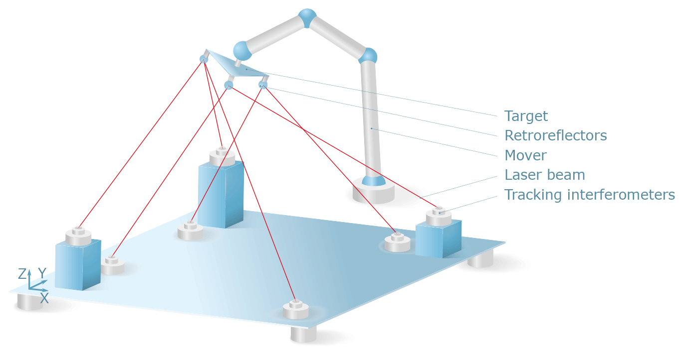
Figure 1Measurement principle of 6-DoF multilateration. A set of tracking laser interferometers is placed in a non-coplanar arrangement and measures a multitude of distances to a target assembly of three retroreflectors.
2.2 Self-calibration
For the calculation of the pose of the moving target, precise knowledge of the system parameters is required. These parameters include the position of the laser interferometer base stations, the unknown dead paths of the interferometers, and the distances between the different retroreflectors of the target assembly. To identify the system parameters, a self-calibration procedure can be used (Nguyen et al., 2013). Self-calibration is possible if an equation system can be set up that contains more linearly independent equations than unknown parameters.
The equation system defined in the previous section contains n(m+p) equations and unknown parameters. If , each position n generates more equations than parameters. In the following, we assume a full 6-DoF movement of a target assembly of p=3 retroreflectors. Hence, m>6 laser interferometers are needed.
Depending on the mover used to position the target, full 6-DoF movements may not be possible. Different self-calibration strategies can be used to calibrate the system parameters for movements with 6 DoF (e.g. industrial robots), 4 DoF (e.g. Cartesian manipulators with one rotational axis) or 3 DoF (e.g. Cartesian coordinate measuring machines, CMMs). To provide a set of reasonable starting values for the optimization problem, the existence of nominal positions and orientations of the manipulator (e.g. a tool centre point or reference point) is assumed. By using such nominal values of the manipulator, the identified system parameters can be orientated in the machine coordinate system of the manipulator.
2.2.1 Self-calibration with 6-DoF movement
Using a 6-DoF manipulator, self-calibration can be performed by positioning the target to n different positions and orientations inside the measurement volume. For a minimum required setup of seven interferometers and three retroreflectors, an equation system with unknowns and 10⋅n equations can be formed. Using a dataset of n≥32 measurement points results in an overdetermined equation system that can be solved iteratively, e.g. using the Levenberg–Marquardt algorithm (Marquardt, 1963). It is important, however, that the dataset should contain target positions with different orientations.
2.2.2 Self-calibration with 4-DoF movement
In case the mover used to position the target is not capable of performing a 6-DoF movement, self-calibration can be performed in two or more steps. If one rotational axis is available, two steps are sufficient.
In the first step, all interferometers are locked into one of the retroreflectors. This configuration results in 7⋅n equations and unknowns. Moving the target to n≥8 positions, the interferometer position and the interferometer dead path can be calibrated.
In the second step, the interferometers are split up to allow the three retroreflectors to be observed. To change the observed retroreflectors, the laser beams of the interferometers must be interrupted, which results in a change in the dead paths. Hence, only the position of the interferometers can be used from the previous calibration step, and unknowns (seven interferometer dead paths, three target distances, target coordinates) need to be determined in this second step. From n≥10 positions including rotations around the available rotational axis, the remaining system parameters can be calibrated.
Depending on the stability of the measurement setup, the calibration of the interferometer positions may need to be repeated from time to time. This may be necessary if the positions of the interferometers change, e.g. due to thermal influences or vibration.
2.2.3 Self-calibration with 3-DoF movement
Self-calibration of a measurement setup that has only 3 DoF is possible if movements on the different axes result in a 3D translation of the retroreflectors. This may be the case in 3D translational movement, 2D translation and rotation along one axis in the plane of translation or rotations around three orthogonal axes. The following strategy refers to a setup with 3D translation.
Similarly to the self-calibration with 4-DoF movement, the first step is used to calibrate the interferometer position by observing one retroreflector. In two consecutive steps, the same calibration is performed by observing the remaining two retroreflectors. Assuming that each retroreflector is positioned on the reference point of the mover, three different positions for each interferometer are calculated. The distances between the different interferometer positions correspond to the distances between the retroreflectors. These first three steps allow the interferometer positions and the target distances to be identified.
In the following step, the interferometers are split up again to observe all three retroreflectors. Consequently, unknowns (seven interferometer dead paths, target coordinates) need to be determined from n≥7 positions.
The result of this serial calibration of the target distances depends on the stability of the target structure and the position feedback of the mover.
The measurement principle and self-calibration strategies described form the theoretical basis for a 6-DoF multilateration setup. Experimental proof of this concept is described in the following section.
Different experiments were performed to evaluate the measurement principle described. In a static measurement setup, self-calibration strategies for 3-DoF and 4-DoF movement were compared. Additionally, dynamic measurements with 3-DoF movement were performed to investigate the system behaviour at high data rates and the evaluation run times. Both experiments are designed to confirm the concept of the 6-DoF multilateration system. Further analysis of the system, e.g. the estimation of the measurement uncertainty from a detailed Monte Carlo simulation, is pending.
3.1 Experimental setup
A precision CMM was used as a mover and position reference with an additional rotational axis in the probing head providing 4-DoF movements. Three cat's-eye retroreflectors were mounted on the probing head in a right-angled triangle arrangement whose legs were 140 and 150 mm in length. The acceptance angle of the retroreflectors is ± 80∘. All retroreflectors were mounted in the same orientation. This allows a rotation of the triple retroreflector target of 360∘ around the surface normal of the target. Rotations around the other two axes are limited by the acceptance angles of the retroreflectors and the positions of the observing laser interferometers. For each target position, this angle can be calculated by subtracting the largest angle between the retroreflector and any two interferometers from the acceptance angle of 160∘. In a typical setup, this maximum rotation angle will not exceed ± 50∘.
Seven tracking laser interferometers were installed along the short sides of the CMM working space in different z positions. For simultaneous data acquisition, six interferometers were triggered externally by one master interferometer. For continuous measurement, the trigger signal was also used for simultaneous readout of the CMM scales. In static measurement mode, length measurements of the interferometers and reference positions of the CMM were acquired after a standstill period of 1 s.
A grid of target positions was recorded in a measurement volume of . Each position was measured twice (except the reversal point for each orientation) in three target orientations of 0, −90 and −180∘. Data processing was performed in Python. The overdetermined equation systems were solved using the Levenberg-Marquardt algorithm implemented in the scipy optimize package.
3.2 Static measurement
In a static measurement, self-calibration with 3-DoF and 4-DoF movement was performed according to the strategies described above. The results for the retroreflector distances are summarized in Table 1.
Table 1Resulting retroreflector distances from self-calibration with 3-DoF and 4-DoF movement.
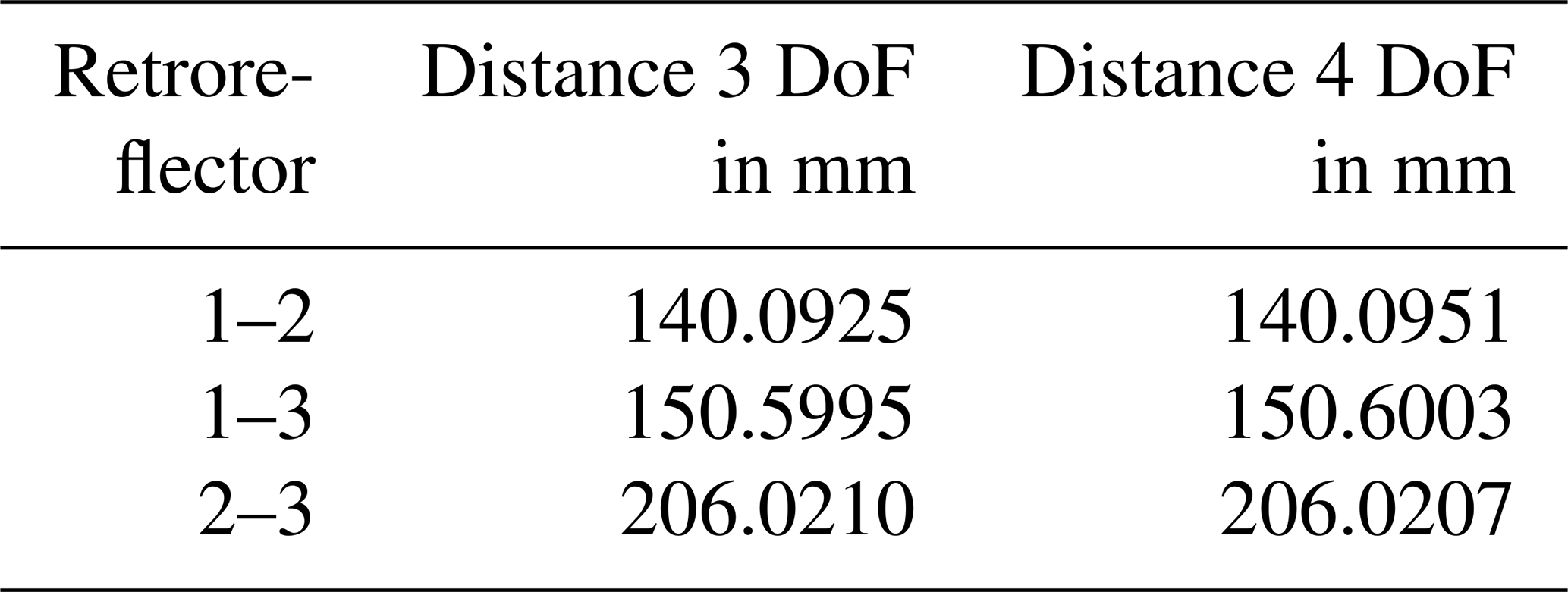
The difference between the calibrated target distances was below 2.6 µm. A comparison to the 6-DoF self-calibration strategy described was not possible because no 6-DoF manipulator was available. Further experiments with 6-DoF movement will be performed in the future.
3.3 Continuous measurement
Continuous measurement was evaluated with a trigger frequency of 200 Hz. The data rate was limited by the readout speed of the CMM scales needed as a reference; the laser interferometers allowed trigger frequencies above 1000 Hz.
Due to the high number of data points acquired at such frequencies, evaluation of a whole dataset, which results in equation systems of several thousand equations, was not reasonable. When considering the use case of the online pose correction of an industrial robot, only the actual position is of interest. Hence, the continuous evaluation took place by solving the equation system in a serial manner for each data point using the pose information of the previous data point as a starting value for the next data point. This required the system parameters to be calibrated beforehand. If all system parameters were known, one data point consisted of seven measured lengths and six unknowns for the target pose.
Evaluation of the continuous dataset took place using Python on a desktop PC with a quad-core CPU, a 3.20 GHz base frequency and 32 GB memory. In this configuration, a run time per data point of 1.3 ms was achieved. Using a more efficient programming language may further improve the evaluation performance.
Due to the delicate surfaces of the retroreflectors, it was not possible to calibrate the position of the retroreflectors in relation to the CMM reference point. In order to compare the results of the multilateration setup with the reference values of the CMM, alignment of the datasets was required. To align the data points from CMM and multilateration data, cross-correlation was calculated for x values of reflector 1 and the CMM reference. Different offsets in the position coordinates were compensated by subtracting the mean value of the first 100 data points of each coordinate. These data points were acquired during standstill before starting the measurement. This alignment allowed the relative distance change calculated from multilateration to be compared to the relative distance change calculated from the CMM.
Figure 2 shows a dataset of 20 000 measurement points obtained during a period of 100 s. For each retroreflector, the relative coordinate deviation from the CMM reference is shown. Additionally, the nominal coordinate position is indicated on the secondary y axis. During movement of the CMM, a deviation of ±20 µm, depending on the moving direction, was observed. During standstill, mean deviations were below 5 µm. Deviation in z showed high noise, especially for retroreflector 2.
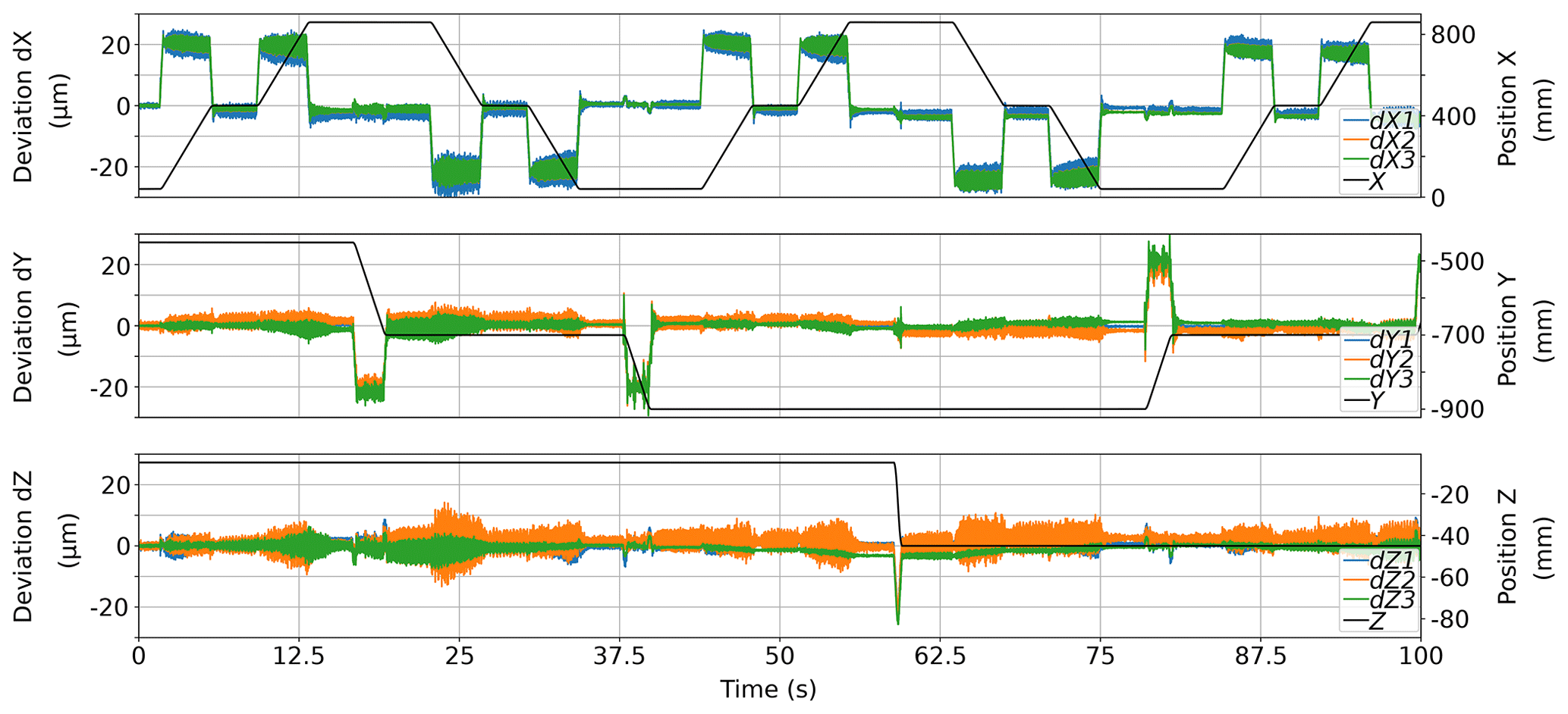
Figure 2Relative coordinate deviation between multilateration and CMM reference for each retroreflector. The primary y axis indicates the relative deviation, while the secondary y axis indicates the nominal position of the CMM reference.
Assuming a maximum deviation of 5 µm for each retroreflector during standstill and a shorter leg of 140 mm, an angular deviation of 71 µrad can be calculated. As mentioned in Sect. 2.1, the accuracy of the orientation can be improved by reducing the deviation of the position estimation of the single retroreflectors and by increasing the distances between the reflectors.
To explain the deviation of 20 µm during movement, two possible effects were identified. Even with an external trigger signal, the data acquisition may be slightly asynchronous. The CMM was set to a moving speed of 100 mm s−1. Thus, the deviation of 20 µm could be the result of a 0.2 ms offset in synchronization. From a repeated measurement with different moving speeds, this effect could be analysed. The second possible effect is a deformation of the observed target or the measurement chain from the CMM reference point to the different retroreflectors. From the identical amplitude of 20 µm for all three retroreflectors on both the x and y axes, a deformation of the target itself seems unreasonable. A deformation of the measurement chain of the CMM could be investigated by changing the acceleration of the CMM.
In this work, a multilateration setup to evaluate the full 6-DoF pose of an observed target was described. The setup used seven tracking laser interferometers to calculate the position and orientation of the target at high data rates. In a proof of concept, measurement points were recorded at a frequency of 200 Hz, which was limited by the readout speed of the reference CMM.
To identify unknown system parameters, different self-calibration strategies for movements with 3, 4 and 6 DoF were developed. Experimental evaluation of the self-calibration using 3- and 4-DoF movements showed good agreement. In a dynamic experiment, deviations between the multilateration evaluation and a reference CMM of 20 µm were observed during movements at a speed of 100 mm s−1. Without movement, the deviation was reduced to below 5 µm in a measurement volume of .
In further experiments, the capability of tracking full 6-DoF movements will be analysed. For such an experiment, establishing a precise reference with a wide measuring range for the orientation of the target will be a major challenge.
The underlying measurement data used in this work can be requested from the authors if required.
JN developed the 6-DoF multilateration evaluation and self-calibration strategies, evaluated the experiments, and wrote the article, JN and MF devised and performed the experiment, and NH and DH provided support for the experiments and the evaluation and reviewed the article.
The authors declare that they have no conflict of interest.
This article is part of the special issue “Sensors and Measurement Science International SMSI 2020”. It is a result of the Sensor and Measurement Science International, Nuremberg, Germany, 22–25 June 2020.
This open-access publication was funded
by the Physikalisch-Technische Bundesanstalt.
This paper was edited by Thomas Fröhlich and reviewed by two anonymous referees.
Lin, Y. and Zhang, G.: The optimal arrangement of four laser tracking interferometers in 3D coordinate measuring system based on multi-lateration, in: IEEE International Symposium on Virtual Environments, Human-Computer Interfaces and Measurement Systems, 2003, VECIMS '03, 138–143, IEEE, Lugano, Switzerland, https://doi.org/10.1109/VECIMS.2003.1227044, 2003. a
Marquardt, D. W.: An Algorithm for Least-Squares Estimation of Nonlinear Parameters, J. Soc. Ind. Appl. Math., 11, 431–441, https://doi.org/10.1137/0111030, 1963. a
Merlet, J.-P.: Parallel robots, no. 74 in Solid mechanics and its applications, 2nd edn., Kluwer Academic Publishers, Dordrecht, Boston, MA, 2006. a
Nguyen, T. T., Weiß, H., Amthor, A., and Ament, C.: Fast and Robust Online Calibration of a Multi-laser Tracking System, in: 2013 Sixth International Conference on Developments in eSystems Engineering, 141–144, IEEE, Abu Dhabi, United Arab Emirates, https://doi.org/10.1109/DeSE.2013.33, 2013. a
Norman, A. R., Schönberg, A., Gorlach, I. A., and Schmitt, R.: Validation of iGPS as an external measurement system for cooperative robot positioning, Int. J. Adv. Manuf. Tech., 64, 427–446, https://doi.org/10.1007/s00170-012-4004-8, 2013. a
Stadelmann, L., Sandy, T., Thoma, A., and Buchli, J.: End-Effector Pose Correction for Versatile Large-Scale Multi-Robotic Systems, IEEE Robotics and Automation Letters, 4, 546–553, https://doi.org/10.1109/LRA.2019.2891499, 2019. a
Takatsuji, T., Goto, M., Kurosawa, T., Tanimura, Y., and Koseki, Y.: The first measurement of a three-dimensional coordinate by use of a laser tracking interferometer system based on trilateration, Meas. Sci. Technol., 9, 38–41, https://doi.org/10.1088/0957-0233/9/1/006, 1998. a
Vincze, M., Prenninger, J., and Gander, H.: A Laser Tracking System to Measure Position and Orientation of Robot End Effectors Under Motion, Int. J. Robot. Res., 13, 305–314, https://doi.org/10.1177/027836499401300402, 1994. a
Wendt, K., Franke, M., and Härtig, F.: Measuring large 3D structures using four portable tracking laser interferometers, Measurement, 45, 2339–2345, https://doi.org/10.1016/j.measurement.2011.09.020, 2012. a
Yang, J., Wang, D., Fan, B., Dong, D., and Zhou, W.: Online absolute pose compensation and steering control of industrial robot based on six degrees of freedom laser measurement, Opt. Eng., 56, 034111, https://doi.org/10.1117/1.OE.56.3.034111, 2017. a