the Creative Commons Attribution 4.0 License.
the Creative Commons Attribution 4.0 License.
 | 22 Sep 2021
Referencing of powder bed for in situ detection of lateral layer displacements in additive manufacturing
Julien Schinn
Tino Hausotte
An increasing number of additive manufacturing (AM) applications leads to rising challenges for the process-accompanying quality assurance. Beside post-processing measurement systems, in situ monitoring systems in particular are currently requested to ensure feedback controlling during AM processes. For data acquisition and subsequent evaluation, a high data quality is of importance. It depends on a high resolution and accuracy of measurement systems, adapted measurement conditions and a reference to the powder bed or component for geometric measurements. Within this scientific study, a new reference system has been implemented into the powder bed to reduce measurement deviations by an abbreviated metrological loop. After data acquisition and image processing layer by layer, the position stability of the reference system has been analysed in relation to the optical measuring system. Based on a contour detection of the reference markers, the evaluation of geometrical process deviations is presented as an essential basis for a closed-loop controlling system. Thermally induced and mechanical drifts within the manufacturing process can be verified by the reference system in the powder bed. As an outlook, two methods are suggested for a process-accompanying referenced detection of the melting pool and resulting contour displacements during additive manufacturing.
- Article
(6916 KB) - Full-text XML
- Companion paper
-
Supplement
(700 KB) - BibTeX
- EndNote


Additive manufacturing (AM) is the general term for processes that are based on a successive addition of materials (ISO/ASTM-52900, 2015). In general it is also known as rapid prototyping (RP) or 3-D printing, which can be divided in numerous process categories (Schmidt et al., 2017; Gebhard et al., 2019). These are characterised by different materials, binding mechanisms and associated different processing steps. In focus of this scientific study is generally the process group of powder bed fusion (PBF) systems as a representative of laser-based process categories. Using the example of selective laser sintering (SLS) with the standard powder polyamid 12 (PA 12), this AM process is also referred to as laser beam melting of polymers (LBM-P) (ISO17296-2, 2015).
After powder application, the sliced AM components are inserted layer by layer into the powder bed by means of a guided laser beam. The manufacturing steps of lowering the building plate, powder application by a double-blade system in the lateral x direction and energy input of the laser are repeated iteratively until the complete additive component has been built up layer by layer in the powder bed (Deckard, 1989).

Figure 1Positioning of optical monitoring systems (a) off-axis, inside, (b) off-axis, outside, and (c) on-axis, outside the process chamber (Lerchen et al., 2021).
All additive technologies have a near-net-shape manufacturing of components with almost unlimited complexity in common. These properties increase the attractiveness of AM for industrial production but are also associated with progressive demands on the manufacturing process. In order to make the process more interesting for industrial series production, further steps of standardisation and comprehensive quality control are necessary in addition to a reduction of production costs. According to Imkamp et al. (2012), a resource-efficient, fast, precise, flexible and controlled manufacturing process requires process-accompanying, metrological quality monitoring. A comprehensive quality assurance is characterised by an observation of the entire manufacturing process, including preprocess, in-process and post-process (VDI3405, 2014). It has been shown that especially optical in-process and in situ monitoring during the auxiliary process times have a great potential to generate relevant measurement data for geometrical feedback control (Schmitt and Damm, 2008). However, precise measuring systems are not effective if the recorded production errors cannot be distinguished from measurement deviations. The measurements of the individual layers should be referenced to each other by a shortened measuring loop of the powder bed and not by the otherwise usual long measuring loop of the entire AM plant.
A comprehensive data acquisition during powder-based AM processes requires referenced in-process monitoring of the region of interest (ROI) within the powder bed layer by layer and a reliable subsequent imaging evaluation. The following sections deal with the state of the art of common optical measuring methods and approaches of reference systems in AM.
2.1 Process-accompanying quality control by optical measurement techniques
The origin of laser-based process monitoring is in the 1980s. From that time until now the generation of information about the manufacturing process has aimed to increase understanding of the process-related interactions (Purtonen et al., 2014). Especially emission and back-reflected radiation during laser beam melting processing have proven to be relevant for a comprehensive optical quality control (Lott et al., 2011). In this context, several optical systems are used for in-process and in situ monitoring of laser beam interactions with the powder. These sensors are mainly classified into camera- and diode-based as well as spectrometric and pyrometric systems (Purtonen et al., 2014).
A further subdivision is made according to the field of application and the positioning of optical measuring systems in the manufacturing plant, illustrated in Fig. 1. A possibility is to integrate the monitoring system into the LBM manufacturing chamber as exemplarily shown in Fig. 1a. This arrangement requires cooling and hermetically shielding against the heat, powder and other environmental impacts. Nevertheless, the process-related temperature controlling may influence the measurement and manufacturing results (Foster et al., 2015; Galovskyi et al., 2015).
Most on- and off-axis configurations are therefore located outside the process chamber. The off-axis sensors of Fig. 1b are aimed directly at the ROI and usually have a large field of view. The optical properties of the monitoring systems, the objectives and lenses, as well as the observation angle and optical distances influence the measuring range (Caltanissetta et al., 2018). Additional fringe projection systems can be used in PBF according to Land et al. (2015) and Zhang et al. (2016) to extract geometrical and surface information of the melting pool. The measuring principle is based on the detection of systematically varied stripe patterns on the powder bed. The individual surface points can be triangulated based on deformed fringes. Further single charged-coupled devices (CCDs), complementary metal oxide semiconductors (CMOS) and photodiodes are at the moment the most frequently used sensors for off-axis image segmentation. Camera-based measuring systems usually offer in situ detection of the powder bed levels and geometrical processing deviations. In addition, light intensities and their different wavelength spectra can be analysed by photodiodes. Extended analyses of the non-visible infrared wavelengths are recommended using a spectrometer or pyrometric measurements of the thermal heat radiation of the melting pool (Purtonen et al., 2014).
Due to their fast response time, photodiodes are also utilised as on-axis sensors, as illustrated in Fig. 1c for in-process detection of the moving melting spot during fabrication. Also, high-speed camera systems may be integrated coaxially in the beam path of the laser and the galvanometer scanner by beam combiners. This arrangement patented by Kruth and Mercelis (2009) allows the actual position and movement of the laser spot to be tracked to evaluate the geometric shape of the melt paths (Lott et al., 2011; Craeghs et al., 2011). Another application of on-axis image processing aims at optical coherence tomography (OCT), an optical imaging technique based on low coherence interferometry. It allows for an analysis of the melting pool surface, the associated fusion depth and the heat distribution (Gardner et al., 2018).
All mentioned optical measuring systems have to be calibrated and focused correctly on the ROI in the powder bed before data acquisition. This step is important for a subsequent alignment of the measuring systems and the deformation correction within image processing. A stable, reliable referencing is further essential for meaningful geometric analysis (Zur Jacobsmühlen et al., 2016).
2.2 Conventional reference system approaches in additive manufacturing
In addition to a high-resolution image acquisition and reliable contour detection, accurate process-accompanying length measurement technology requires a suitable reference system. Due to the powder application in LBM, it is difficult to determine the precise position of the coordinate origin of the building plate, the powder bed and the AM components. An additional detectable reference system with a stable position in relation to the powder bed is recommended. In contrast to a tactile coordinate measurement of solid, crystallised, additive manufactured reference points according to Salmi et al. (2013), tactile probing of the powder bed or melting pool during the AM process is not useful.
Optical, non-contact referencing is preferred for AM process monitoring and control layer by layer. One approach according to Cooke and Moylan (2011) is to use the frames of the powder box or the housing of the AM plant as referencing systems. Depending on the field of view, a matching of the camera with the machine coordinate system is required. The disadvantage of referencing the frame of usually steel-made plant housing is an increased thermal elongation during the temperature-controlled manufacturing process. In addition, a large measuring field is required, shown in Fig. 1a and b. The examined referenced distances are large because the AM parts are preferably manufactured in the centre of the building plate. Consequently, the precise length measurement is subject to increased measurement uncertainty because of the thermal influence and poor image resolution of the large observation field.
Zur Jacobsmühlen et al. (2014) resort to a further concept based on an additive manufacturing of reference markers layer by layer in the marginal areas of the ROI. In the associated investigations, significant plant- and process-related lateral deviations of the AM reference markers up to 156 µm have been detected. This positional inaccuracy is attributed to the fact that the additive manufactured reference contours as well as the referenced melting pool are exposed to process-related manufacturing influences. Furthermore, it is not possible to manufacture exactly round and dimensionally stable reference circles. In total, the concept is dependent on each lateral layer deviation and does not refer to a global stable reference system.
As shown in the previous sections, current referencing approaches in additive manufacturing still have numerous deficits. To reduce measurement deviations for a reliable measurement data acquisition and in-process control, a new referencing concept will be presented within the following sections.
3.1 Principle of shortening of the measuring loop
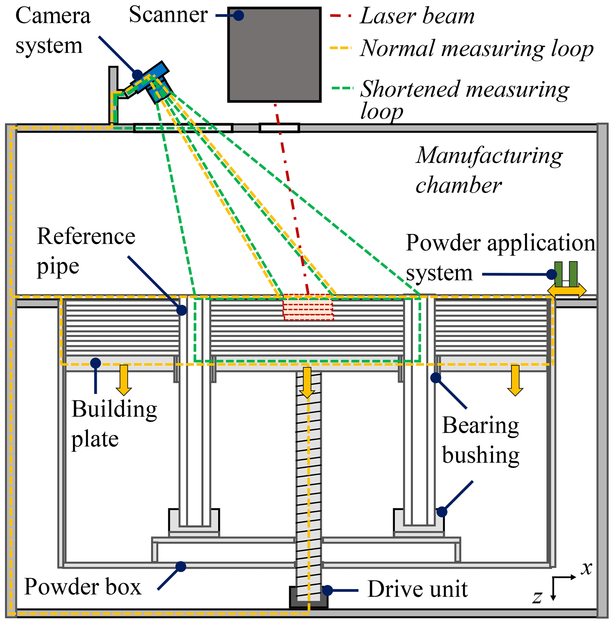
According to Hausotte (2015), the main problems of the existing referencing concepts are numerous measuring influences caused by mechanical and thermal variations along the measuring loop. In the case of LBM, the normal closed measuring loop of Fig. 3 includes the camera system and its tripod, the frame of the manufacturing plant, the drive unit, building plate, powder box with the powder bed and the melting pool. The individual geometric variations (e.g. thermal expansion) of all these connected components of the measuring loop may be influenced by process conditions and affect the overall measurement result (ISO25178-600, 2019).
Even small changes in the length of single components lead to a drift of the measuring system relative to the machine coordinate system (Cooke and Moylan, 2011). Precise measurements in the micrometre range are additionally influenced by mechanical vibrations, which are transferred to the sensitive measuring systems coupled with the manufacturing plant. These are caused by mechanical movements, for example during powder application (Zur Jacobsmühlen et al., 2014).
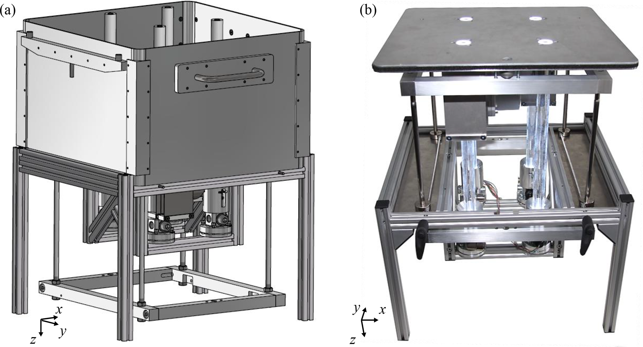
Figure 2Extended EOS P380 powder box: (a) the CAD figure and (b) the real powder box body (without housing) with raised building plate and illuminated reference pipes.
In contrast to conventional referencing concepts in Sect. 2.2 using the frame of the powder box or additionally additive-manufactured reference markers, a new referencing approach is presented. Four low-expansion quartz glass pipes are integrated into the powder bed as illustrated in Figs. 3 and 2. As a result, an area-related closed reference space is created at the corners of the ROI in the observed powder bed plane. A position stable reference system is further characterised by small fluctuations of the reference positions, which are specified in Sect. 5 (ISO17450-4, 2017).
The measuring loop is significantly shortened according to Fig. 3 by the direct optical detection of the reference pipes integrated in the powder bed. Due to the few temperature stable components along the shortened measuring loop, the measurement setup is more invariant, especially with regard to thermal measurement influences. Another advantage for optical monitoring is the smaller measuring field, which only contains the melting pool and powder bed between the reference markers. Thus, a higher pixel resolution in the ROI has been realised, which leads to better results in contour evaluation in Sect. 4.2.2.
3.2 Constructive realisation of the reference system integrated in the powder bed
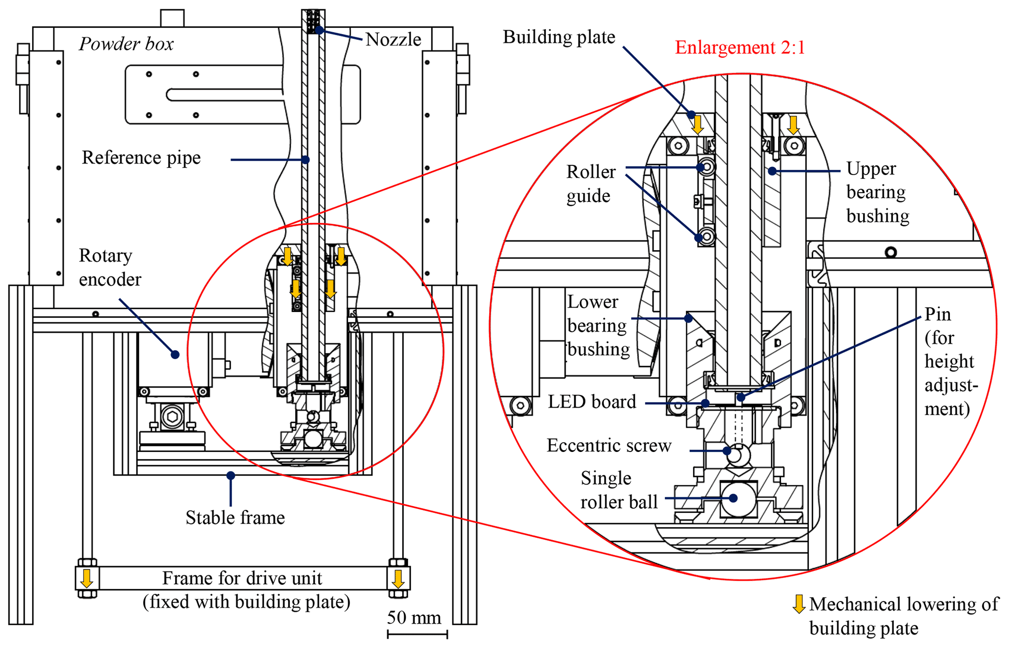
As already mentioned, the constructive realisation of the new referencing concept requires an integration of quartz glass pipes into the building plate. For the present investigations, the powder box of an EOS P380 LBM system has been extended by reference modules, illustrated in Fig. 2. Several holes for the reference pipes are initially required in the building plate at the edges of the construction area. The pipes are inserted into the building plate from above. Lateral guidance is provided by bearing bushing in the building plate with roller guides. In the LBM process, the increasing surrounding powder bed has an additional supporting effect. As shown in the inset of Fig. 4, the reference pipes are inserted into a further bearing bushing mounted on a stable frame at the bottom of the powder box. The pipes are vertically supported on a single roller ball, which ensures a lateral clearance. Only the powder bed together with the building platform determines the lateral position and inclination of the pipes.
The vertical position is further determined by means of an eccentrically mounted, height-adjustable pin. During the AM process, the reference pipes remain constantly at this height. Only the building platform is lowered by the drive unit, which is connected by another mobile frame. An optional measurement of the mechanical lowering is possible by additional rotary encoder systems. These are attached below the building plate. The friction wheel of the rotary encoder rolls on the surface of the quartz pipes. Based on the detected angle of rotation of the friction wheel, the lowering of the building plate can be calculated, which is an indication for the set thickness of the actual powder layer.
Before starting the manufacturing process, the upper ends of the reference pipes are positioned at a vertical distance of 20 µm under the powder application system. This avoids mechanical contact during powder application. At the same time most of the powder residues are removed from the surfaces of the pipes. To ensure complete exposure at the ends of the reference pipes for optical detection, additional suction of individual powder particles through the nozzle and the entire length of the reference pipes is possible.
An additional illumination is provided by LED boards, which are installed below each referencing pipe. The light is guided along the wall of the reference pipes to the powder bed level and left diffusely from the rough front surface of the pipe. The optical contrast to the surrounding white PA 12 powder is improved, which is still necessary for a solid edge detection of image processing.
The optical in situ analysis of the referenced powder bed level requires an image preprocessing of the acquired data layer by layer during the LBM-P process.
4.1 Optical detection of the reference system
The monitoring of the reference system in the powder bed is done by two monochrome, high-resolution 26-megapixel stereovision cameras. The NanoXL-M5100 cameras are mounted outside the process chamber according to Fig. 3 and are aligned with an angle of 18∘ to the powder bed. With a pixel size of 4.5 µm×4.5 µm, a lateral resolution of 27 µm in the ROI is achieved. Images from each production layer are taken, as illustrated in Fig. 5a, which include the illuminated reference pipes in the powder bed. With regard to reduced optical influence of the ambient illumination on edge detection, images are recorded without external illumination as shown in Fig. 5b. Therefore, the additional attached external white-light sources and the radiant heaters are switched off for the short time of image acquisition.
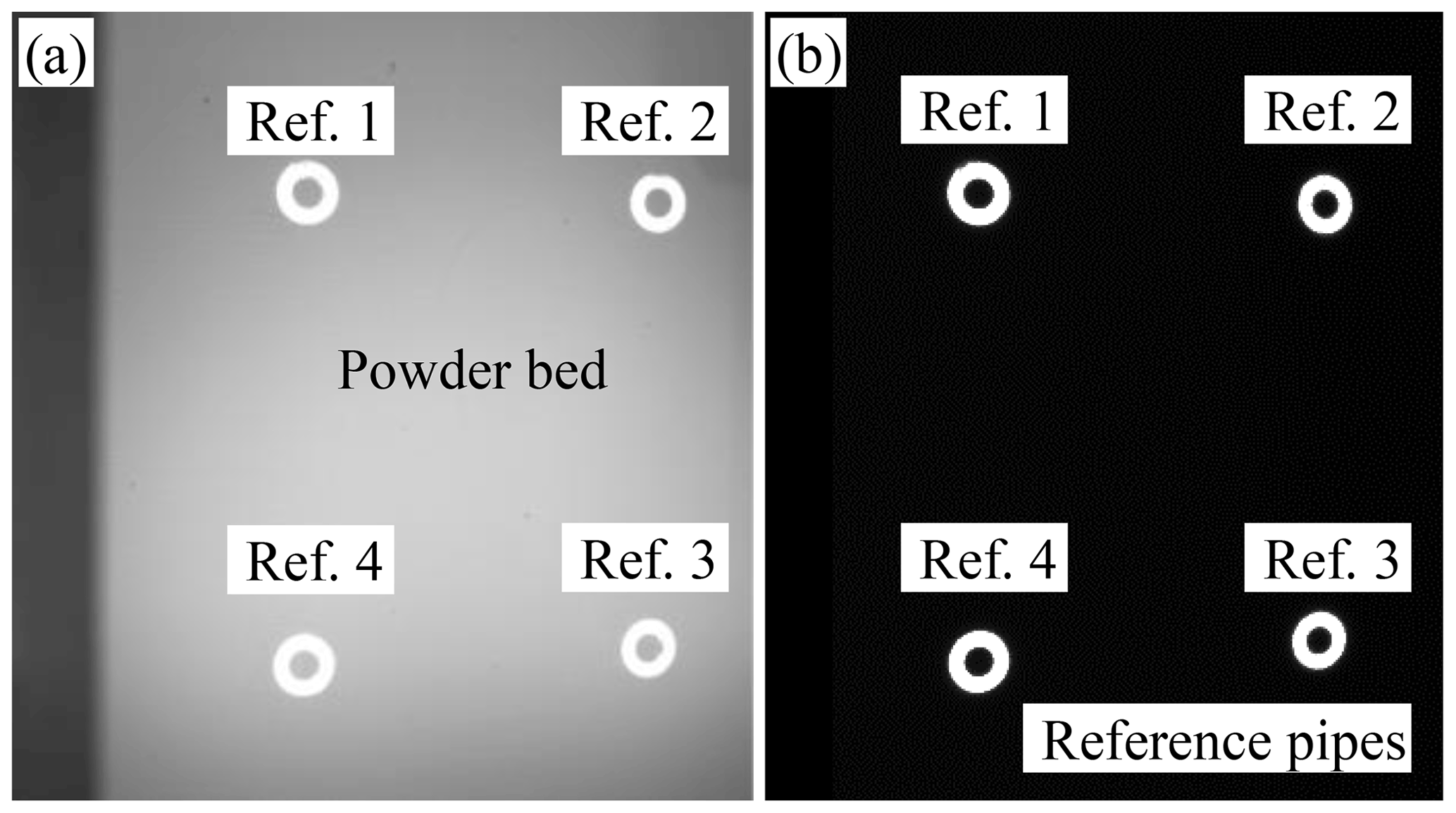
Figure 5Original image of powder bed plane with illuminated referencing pipes, (a) under process conditions and (b) without external illumination.
4.2 Image preprocessing of measurement data
Despite the precise adjustment of the camera and the adapted depth of focus using a tilt shift adapter, image preprocessing of the recorded in situ images is necessary (Scheimpflug, 1904). Important for a reliable edge detection is the following step of undistortion and rectification, which is necessary to get correct length measurements.
4.2.1 Rectification and undistortion
Image deformations result as a consequence of the angled viewing direction of the measuring sensors or optical effects by lens and perspective distortions. Figure 6a shows the deformations of the original image by the drawn, actually rectangular auxiliary lines. Rectification and undistortion steps are essential for a precise determination of the reference world coordinate system and a distance determination referenced to it. Based on the intrinsic and extrinsic parameters of the calibration data, characterising the camera orientation relative to the measuring field, deformation correction is performed by a rectification algorithm on MATLAB (Heikkilä and Silvén, 1997; Zhang, 2000). Each point P (x0,y0) of the original images is transformed into a corresponding deformation-corrected point P (x,y). A non-shape-maintaining transformation of the points in relation to the entire image in Fig. 6b is performed to compensate the perspective image deformation. As a result of the rectification, the edges of the image are bevelled, but the centre of the image is reproduced realistically as if the viewing angle is perpendicular to it (Zur Jacobsmühlen et al., 2016). The last step of image preprocessing includes an area restriction to a smaller measuring field, which is shown in Fig. 6b. This reduces the amount of irrelevant image information limited to a smaller ROI of the investigations between the reference markers.
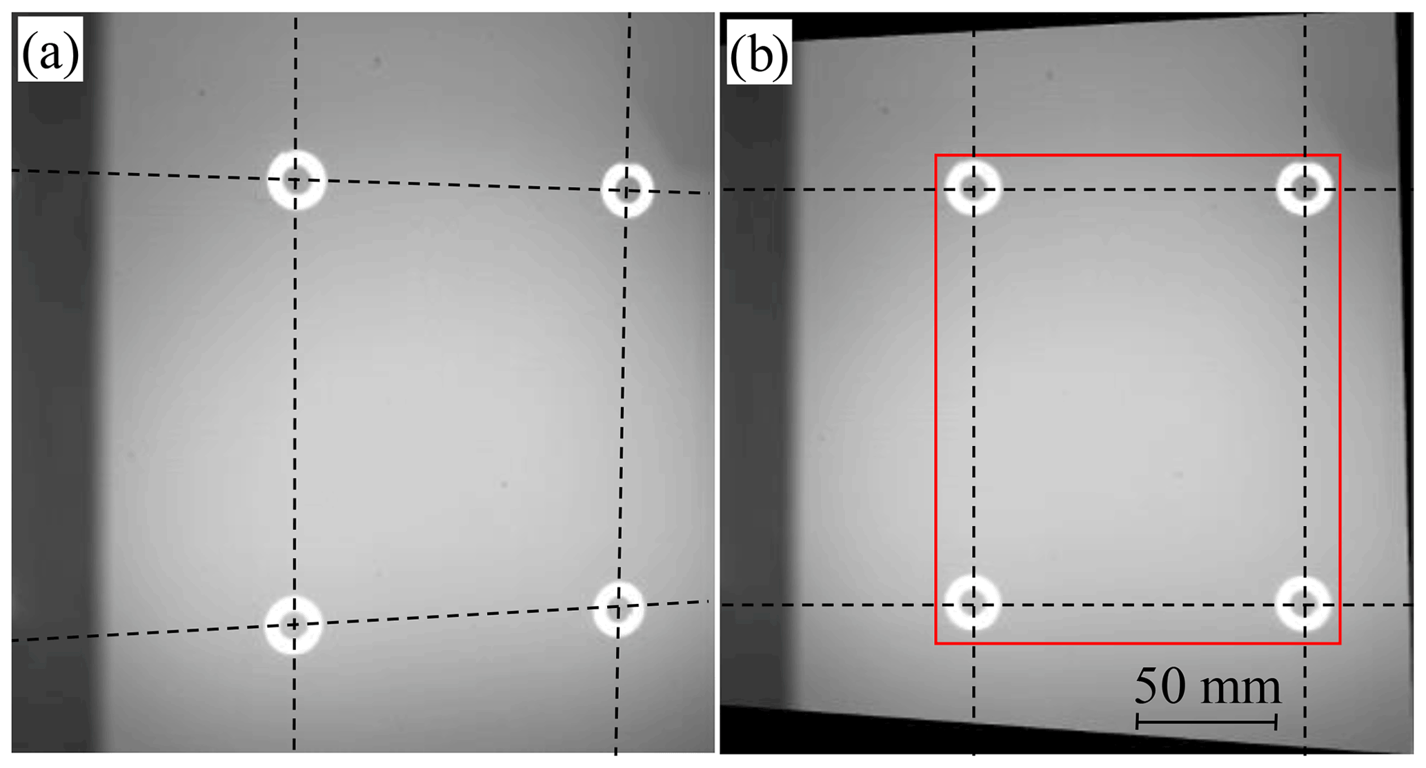
Figure 6Correction of image deformations of the (a) original image to a (b) rectified and undistorted image with subsequent area delimitation of the ROI.
4.2.2 Contour evaluation of reference markers
The actual image evaluation of the inner circles of the referencing pipes in Fig. 7 is performed based on the processed image data sets. The edge detection MATLAB algorithm according to Canny (1986) allows for an accurate and reproducible analysis of reference positions. The recorded, deformation-corrected images are subjected to Gaussian filtering by default. Most ambient noise is suppressed this way, resulting in fewer incorrectly assigned edges. In Canny contour evaluation, the intensity gradients are evaluated by partial derivatives of the filtered grey values in the image. In a next step of non-maximum suppression, the adjacent image points and their gradient directions are compared. Only the largest local maximum of image points is retained. During the actual edge detection, the high-contrast contour is assigned by means of a double-threshold detection. If there is a sufficient contrast difference between contours and background, which manifests in a steep hysteresis transfer function, a stable, reproducible and clear assignment of the reference marker positions is achieved (Canny, 1986; Xiao et al., 2020).

After the individual round reference contours have been determined in each layer, the corresponding centre-of-gravity coordinates are identified. The individual reference positions are combined to a common reference coordinate system origin according to Eqs. (1) and (2).
The averaged centroid Ref. serves as a global reference system origin for the following evaluations. The orientation of the coordinate system results from each image. In the next section it will be analysed whether the positional stability of the combined reference origin and the orientation can be guaranteed in comparison to the individual reference marker positions.
Before the referencing concept is transferred to the actual AM process, the position accuracy of the reference system in the powder bed has to be verified in relation to the camera system and by the variation of the reference points to each other. At first it cannot be differentiated whether the analysed contours really shift in the image section or if the deviations are caused by a thermomechanical drift of the camera system and the long measuring loop. This fact is a motivation for the following partial analyses to specify the influences on the individual components in the measuring loop. Also, in the shortened measuring loop a distance determination is carried out by calculating the six Euclidean distances d (Ref. i, Ref. j) between the four reference pipes according to Eq. (3).
Figure 8 illustrates all conceivable distance combinations of widths W, lengths L and diagonals D between the reference pipes and the ideal distances (Wideal, Lideal) between the drillings of the building plate.

Based on the evaluation of the fluctuation of the determined distances, the position stability of the complete reference system can be assessed for the shortened metrology loop. Beside the analysis of the lateral movements of the reference system in the x and y direction, it is also investigated whether a rotation is caused by the variable processing conditions. The rotational deviations may lead to a rotation of the individual images by the rotation angle δ in the lateral directions according to Eqs. (4) and (5).
The relative displacements of the reference pipes to the camera system Δx and Δy are an essential evaluation criterion for the analysis of the relative rotation of the coordinate system. They can be calculated by the following Eqs. (6)–(9).
In order to minimise optical influences caused by brightness fluctuations during the LBM process on the edge detection of the reference pipe positions, the subsequent analyses are performed without external illuminations. Initially, the position stability under thermal process conditions is checked. The influence of the mechanical powder application on position deviations of the reference system is examined in a further step.
5.1 Verification of thermal drift under process conditions
The thermal influence on the camera and the reference system are analysed through a comparison of the reference positions from room temperature to process conditions in the same monitored layer. As shown in Fig. 9a, the origins of the total reference coordinate system are reproducible, detected in 30 images at room temperature of 23 ∘C. This is expressed by the standard deviations of 1.1 µm in the x direction and 0.4 µm in the y direction, which are comparatively small, even for long-term measurements over 90 min. The positions of the individual reference pipes fluctuate nearly identically to the common coordinate system origin. All distances between the reference pipes of the 30 repeated images at room temperature in Fig. 10a show a low standard deviation <0.7 µm. This fact also indicates reproducible length measurements without major external disturbances.
A comparison of the rotatory components Δxrot and Δyrot in Fig. 11a confirms these observations. The associated standard deviations are 0.4 µm and 0.3 µm and point to an insignificant rotation within the images (with a correlation coefficient r(Δxrot, ). The rotation angles δx and δy are both smaller than rad and negligible. The images are not rotated significantly to each other.
Under approximately homogeneous process conditions of 168 ∘C in Fig. 9b, a reproducible position detection of the reference system is again available. Random measuring deviations of about ±15 µm with standard deviations up to 8.2 µm are observed within the evaluations of the 30 recorded in situ images. Even if short-term and long-term measurements of individual positions of the reference pipes show larger thermal-direction-dependent standard deviations between 10–20 µm, a relatively stable combined reference coordinate origin can still be realised. The averaging of the four reference positions makes the entire system more robust against individual position deviations.
The individual inhomogeneous fluctuations due to thermally induced expansion or air streaks cause slightly increased positional variations of the reference. Thus, the determined distances of Fig. 10b show higher fluctuations with standard deviations of 13.5–19.1 µm compared to the regarded case at room temperature. In comparison to other referencing concepts of lateral shifts of the referenced melting pools known from literature, these deviations between the referencing pipes are small (Zur Jacobsmühlen et al., 2014).
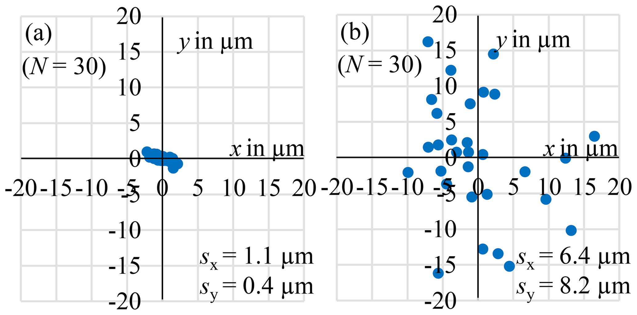
Figure 9Temperature-dependent origin deviations of the total referencing coordinate system at (a) room temperature (∼23 ∘C) and (b) processing temperature (∼168 ∘C).
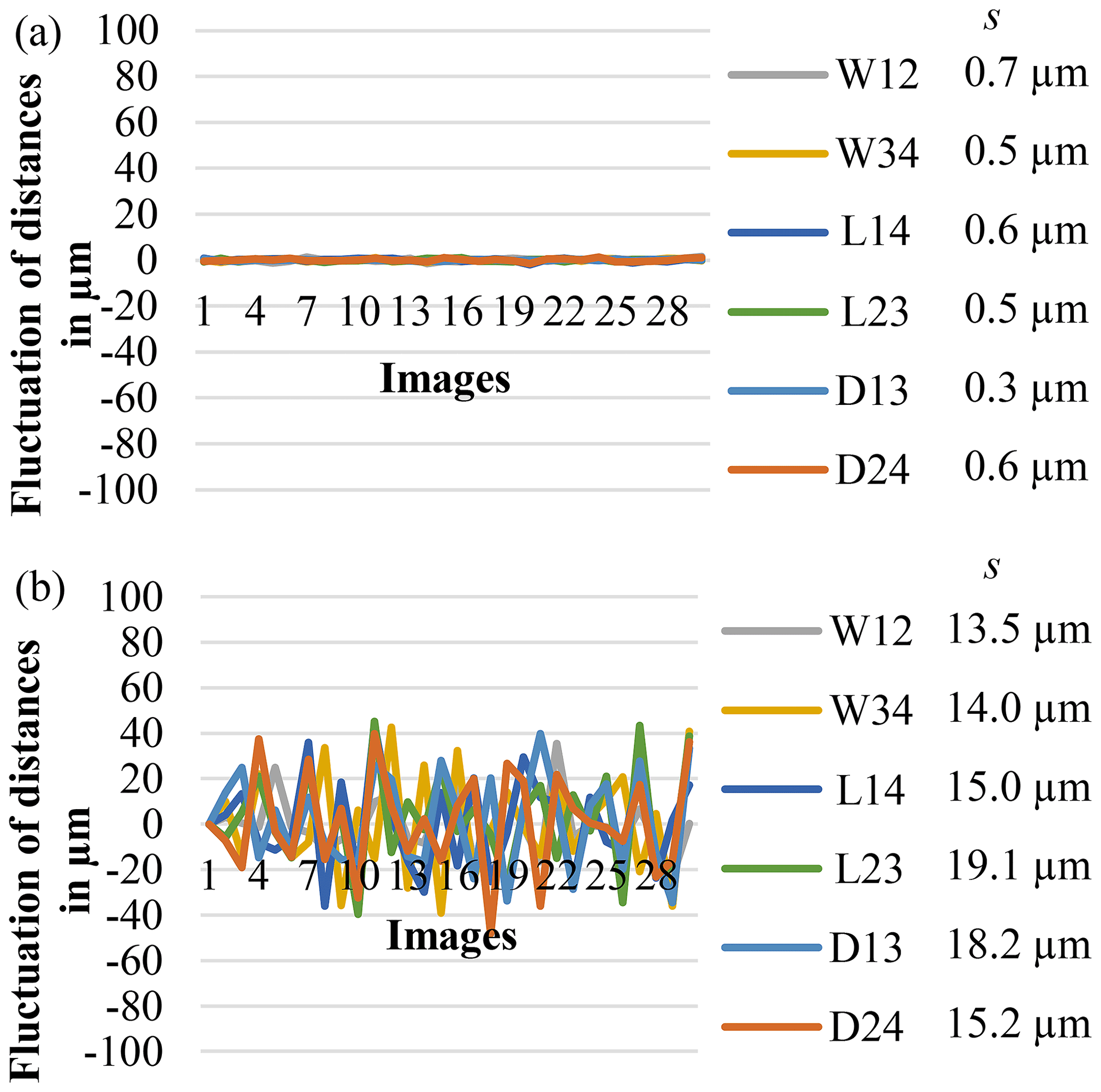
Figure 10Fluctuation of determined distances of the reference pipes at (a) room temperature (∼23 ∘C) and (b) process temperature (∼168 ∘C).
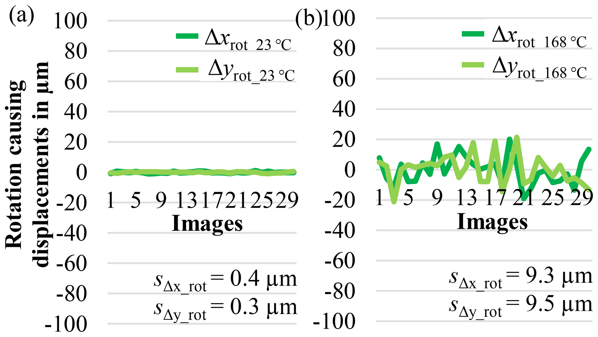
Figure 11Rotation causing displacements of rotatory components Δxrot and Δyrot of the reference pipes at (a) room temperature (∼23 ∘C) and (b) process temperature (∼168 ∘C).
According to Fig. 11b, the rotatory components Δxrot and Δyrot of the analysed 30 images at 168 ∘C have standard deviations of 9.3 µm and 9.5 µm. The rotation angles δx and δy are again negligible with rad. The camera system does not rotate significantly under homogeneous temperature conditions. In total, the new reference system has a good repeatability, with relatively small thermally induced position and rotatory deviations under homogeneous process conditions, and enables reproducible length measurements.
However, the influence of temperature changes on the measuring system cannot be neglected, especially during the heating phase. By analysing the influence of high temperature changes, this effect is obvious. Depending on the material and temperature control of the AM plant, the heating phase usually takes 1.5–2.5 h. Due to the subsequent, controlled preheating of the building chamber, a significant thermal drift of several hundreds of micrometres (µm) of the reference system relative to the camera system (or vice versa) is observed, as illustrated in Fig. 12.
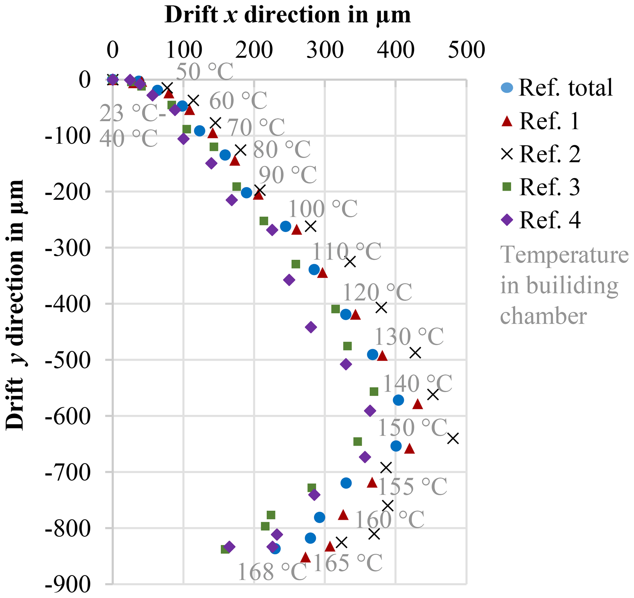
Figure 12Thermal drift of reference system relative to the camera system (or vice versa) during heating phase.
This drift has a significant influence on the calibration file, which is determined at room temperature by default and has to be replaced by a calibration under process conditions. The position changes during heating phase either have to be arithmetically considered or a new camera calibration has to be performed under process conditions. Each component of the long measuring loop may exhibit thermally induced length changes ΔL, which can be calculated individually according to Eq. (10) (ISO14253-2, 2011).
A process-related heating of ΔT=120 K is measured on the quartz glass pipes. Due to the low coefficient of the quartz material with a thermal expansion of αquartz glass = , it can be assumed that the relative thermal length changes ΔL are mainly caused by thermal changes in the length of the aluminium tripod of the camera or other components of the long, orange measuring loop of Fig. 3.
An important indication that the components of the long measuring loop are responsible for the thermally induced deviations is the changes in lateral distances between the individual pipe ends. According to Fig. 13, there is an increased fluctuation of distances with higher temperatures, which is not caused by displacements of the positionally stable, temperature-insensitive referencing system, according to the previous investigations. The deviations in length measurements can be attributed to temperature-related changes in the length of the mounting frame and the mounting of the camera system. Heat flicker due to the heated temperature layers in the installation space can additionally lead to air streaks, which falsifies the optical measurements.
The evaluation of the rotatory components Δxrot and Δyrot between the images in Fig. 14 shows increased rotation causing displacements.
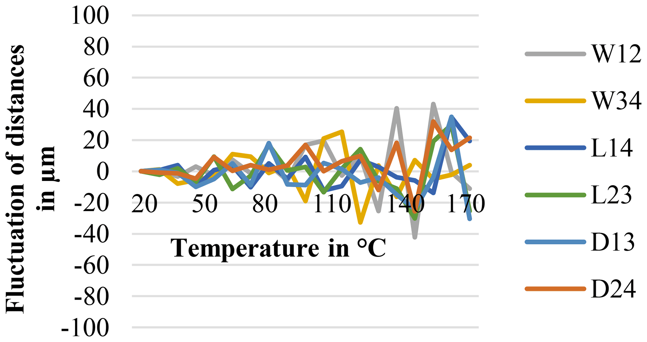
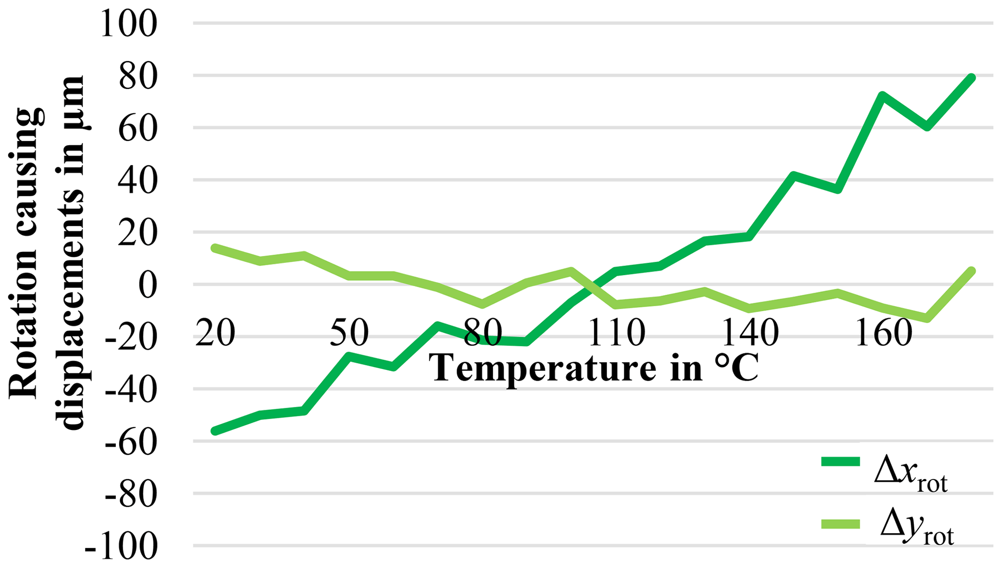
Figure 14Rotation causing displacements of rotatory components Δxrot and Δyrot of the reference pipes during preheating.
In particular, the rotation coefficient in the x direction is drifting with an increasing temperature in comparison to the examined homogeneous conditions. The significance of the observed thermal drift and correlation in the lateral directions can be confirmed by the correlation coefficient r(Δxrot, with a Pearson coefficient of p = 0,1 % < 5 %. In total, the standard deviations of the thermal-influenced distance determination of the shortened, green measuring loop of Fig. 3 and the corresponding evaluations in Fig. 13 show smaller fluctuations compared to the position fluctuations of the unshortened measuring loop determined in Fig. 12. Thus a higher measuring reliability can be achieved with the new referencing concept.
5.2 Verification of mechanical drift caused by powder application
In addition to the thermal influence, the mechanical drift of the reference system by powder application has been investigated under processing conditions of 168 ∘C. It has to be shown whether the force from the powder application system is transferred to the powder bed.
In a preliminary examination without powder on the building plate, it has been confirmed that the powder application system does not influence the detected position of the reference markers. This is an important basis for subsequent comparative tests with a filled powder box under homogeneous process conditions.
Even if no contact between the powder application system and the reference system exists, because of the gap of 20 µm described in Sect. 3.2, regularly alternating position shifts of the single reference pipes and the common coordinate system origin are observed in Fig. 15. This was expected because of the force transmission through the powder, which affects the referencing system coupled to the build platform and the entire powder bed. The single reference position of pipe 2, exemplarily evaluated in Fig. 15a, shows fluctuations of about ± 60 µm, whereas the total origin in Fig. 15b is more robust and only fluctuating in the range of ± 30 µm. In summary, the mechanical displacements of the 20 origins are dominant in the x powder application direction with a standard deviation of 54.1 µm and 30.9 µm for the common reference origin in comparison to its orthogonal y direction.
The distances between the reference pipes are also influenced by this mechanical drift. The standard deviations of the determined lateral distances are increased to 31–56 µm as illustrated in Fig. 16. The reason for this increased fluctuation in measured values is the combination of the thermal influence at 168 ∘C and the observed force effect of the powder application system on the powder bed and the single reference pipes. The rotatory components Δxrot and Δyrot are also influenced in a similar way and show comparable standard deviations of sΔx=27.7 µm and sΔy=24.2 µm according to Fig. 17. Even if the observed lateral fluctuations are dominated by the mechanical influence of the powder application system, a verifiable lateral displacement of the complete powder bed can be proven by the reference system.
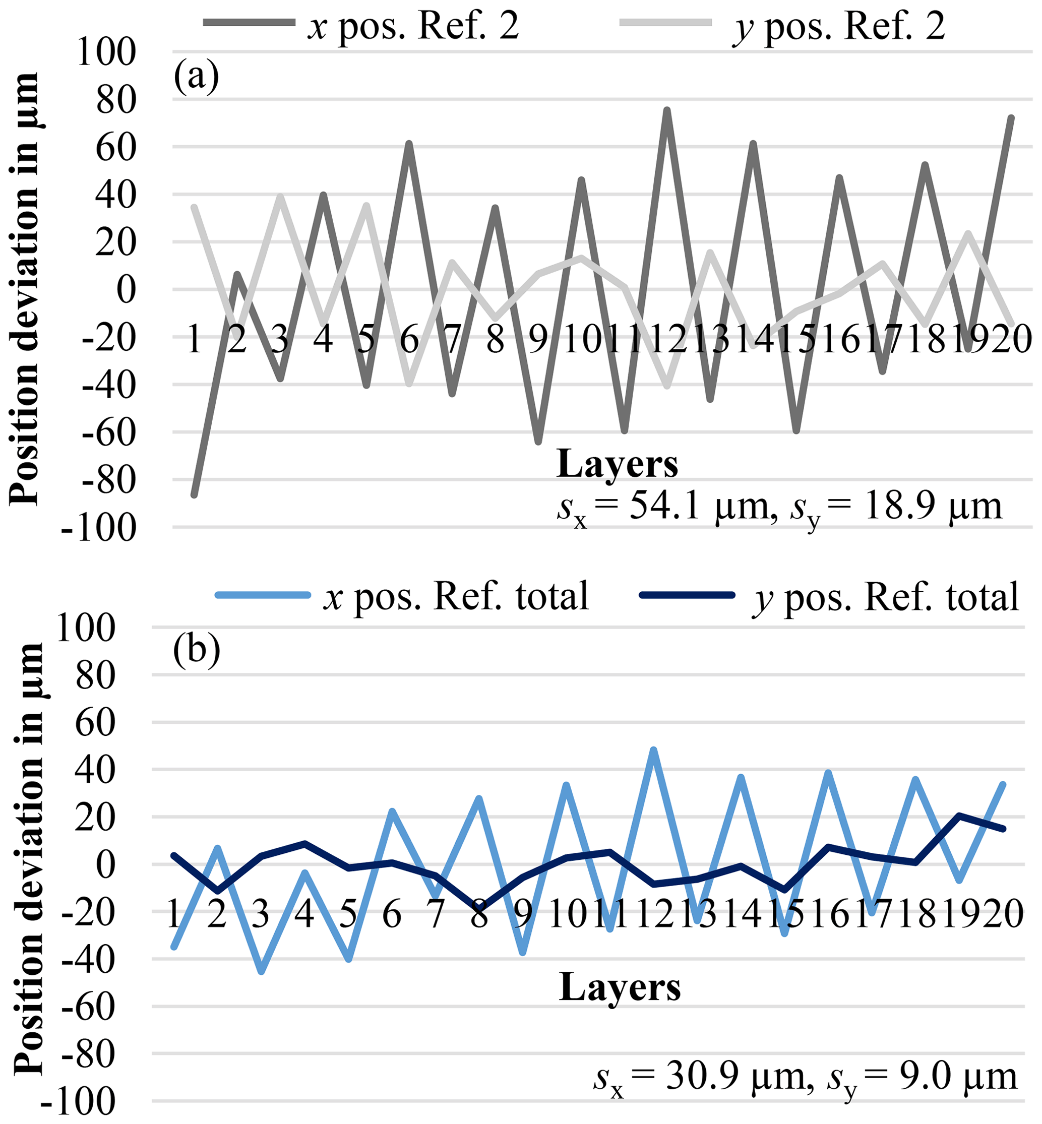
Figure 15Mechanical influence of powder application to the referencing position under process conditions (∼168 ∘C) of (a) the reference pipe 2 and (b) the total reference origin.

Figure 16Fluctuation of determined distances of the reference pipes at process temperature (∼168 ∘C) with the mechanical influence of powder application in the x direction.
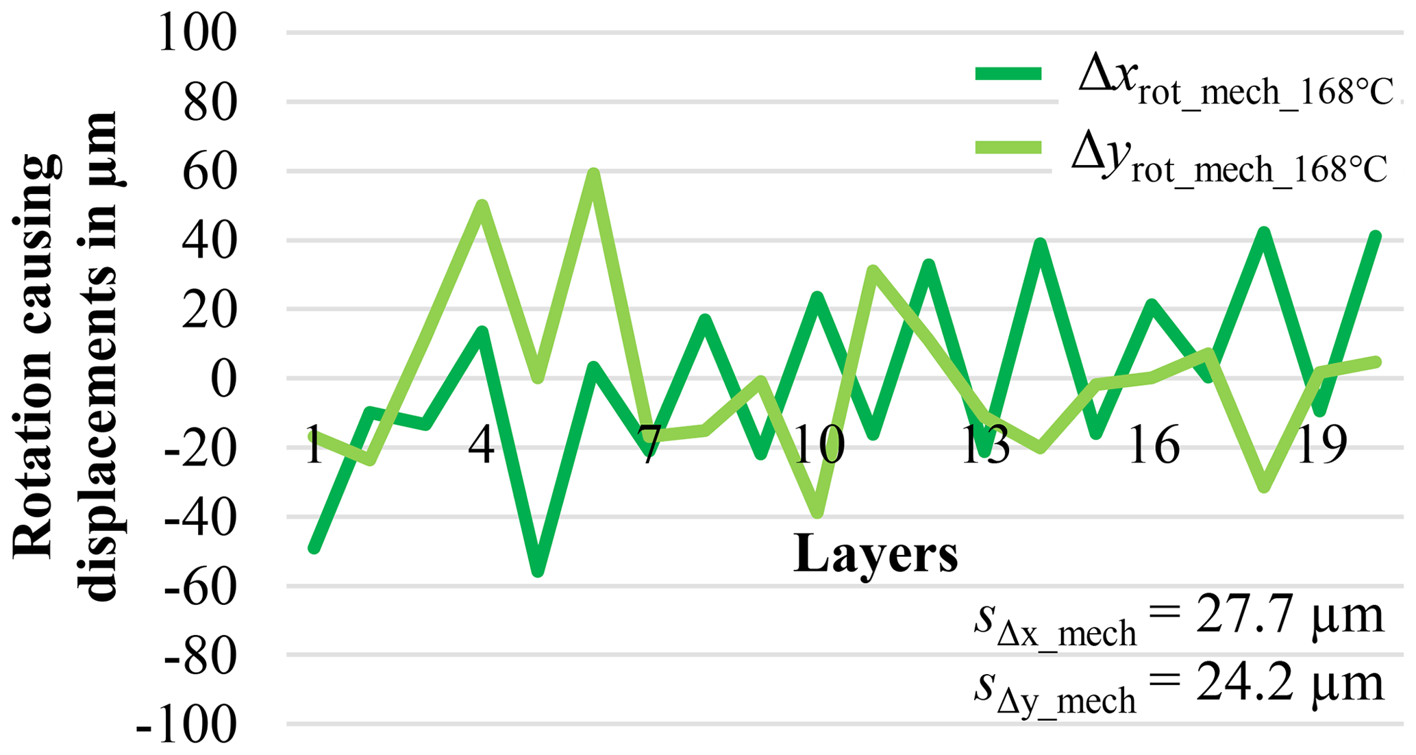
Figure 17Rotation causing displacements of rotatory components Δxrot and Δyrot of the reference pipes at process temperature (∼168 ∘C) with the mechanical influence of powder application in the x direction.
In addition to the presentation of the referencing concept and its accuracy in the powder bed relative to the camera system (or vice versa), further investigations will record referenced melting pool contours layer by layer. A subsequent paper deals with associated methodical approaches for optical in situ contour verification of referenced lateral melting pool displacements (Lerchen et al., 2021).
A first approach is a referenced in situ distance determination of the melting pool directly after the energy input of the laser. Based on small measuring distances for the referenced melting pool contours, realistic evaluations for quality assurance are achieved. The individual positions of the molten contours can directly be compared with each other. This allows for an evaluation of local manufacturing deviations of the scanner and other measuring effects between the layers.
Additionally an assessment of contour displacements is aspired to by comparing the melting pool position before and after powder application. The data acquisition of the powder-covered melting pool contours leads to further challenges in terms of edge detection. A comparison of these data sets provides information layer by layer about the mechanical influence of the powder application system on lateral contour displacements. Here, it will be proven if the entire referenced powder bed including the additive components is systematically shifted as a function of the direction of powder application (Lerchen et al., 2021).
In summary, it has been shown that the presented referencing concept can be used as a stable reference system for process monitoring. By integrating the reference pipes into the ROI of the powder bed, the measuring loop is shortened, and length measurement deviations are reduced. The additional internal illumination of the reference markers allows for an increased contrast to the surrounding powder bed and thus a more robust contour detection. Individual manufacturing and measurement deviations can be specified separately by the referencing concept. The characteristic of low thermal expansion quartz glass material of the reference pipes ensures a comparatively small thermal expansion in relation to the referencing approach with the edges of the powder box. Also, mechanical influence due to the force transmission of the powder application system on the entire powder bed can be characterised. This allows for better knowledge of process-related lateral displacements. In the present case, the directional influence of the powder application system has been identified as the main influence of lateral manufacturing displacements. The reference system remains detectable through all production layers during the AM process. The distance determination within the reference systems shows a further advantage of the shortened measuring loop. Referenced distances to the reference system have an overall lower susceptibility to process-dependent fluctuations, which manifests in reduced standard deviations.
As further improvement approaches, a stiffening of the guide springs of the upper bearing bushing is aimed for in order to increase the lateral guidance and positioning. The restricted resolution of the existing camera system is still considered a disadvantage, which reaches its limits in the evaluation of two-digit lengths in the micrometre range. This is just sufficient to determine trends in length measurement for the present investigations.
The software code used can be made available upon request from the authors.
The raw data used can be made available upon request from the authors.
The supplement related to this article is available online at: https://doi.org/10.5194/jsss-10-247-2021-supplement.
ML led the editing and review process and contributed data curation, formal analysis, investigation, methodology, software, supervision, validation, visualisation and writing of the original draft. JS contributed construction and mechanical implementation. TH was responsible for the project administration and the conceptualisation, methodology, construction process, funding acquisition, analysis, editing and idea for the referencing concept and system. Additionally, TH supported the review process.
The authors declare that they have no conflict of interest.
Publisher's note: Copernicus Publications remains neutral with regard to jurisdictional claims in published maps and institutional affiliations.
The authors want to thank the German Research Foundation (DFG) for funding the Collaborative Research Centre 814 (CRC 814) – Additive Manufacturing. The software adapted for contour detection was further supported by the students Jacob Hornung and Yu Zou (Lerchen et al., 2021).
This research has been supported by the Deutsche Forschungsgemeinschaft (Project-ID 61375930 – subproject C4)
This paper was edited by Rainer Tutsch and reviewed by two anonymous referees.
Caltanissetta, F., Grasso, M., Petrò, S., and Colosimo, B. M.: Characterization of in-situ measurements based on layerwise imaging in laser powder bed fusion, in: Additive Manufacturing, Elsevier publisher B.V., 24, 183–199, https://doi.org/10.1016/j.addma.2018.09.017, 2018. a
Canny, J.: A computational approach to edge detection, in: IEEE Transactions on pattern analysis and machine intelligence, PAMI-8–6, 679–698, https://doi.org/10.1109/TPAMI.1986.4767851, 1986. a, b
Cooke, A. L. and Moylan, S. P.: Process intermittent measurement for powder-bed based additive manufacturing, in: An Additive Manufacturing Conference. Proceedings of the 22nd International SFF Symposium, Austin, Texas, 6–8 August, 8–10, 2011. a, b
Craeghs, T., Clijsters, S., Yasa, E., and Kruth, J.-P.: Online quality control of selective laser melting, in: An Additive Manufacturing Conference. Proceedings of the 22nd International SFF Symposium, 6–8 August, Austin, Texas, 212–226, 2011. a
Deckard, C. R.: Method and apparatus for producing parts by selective sintering, U.S. Patent 4,863,538, University of Texas, Austin, 1989. a
Foster, B. K., Reutzel, E. W., Nassar, A. R., Hall, B. T., Brown, S. W., and Dickman, C. J.: Optical, layerwise monitoring of powder bed fusion, in: 26th international Solid Freeform Fabrication Symposium (SFF), 10–12 August, Austin, Texas, 2015. a
Galovskyi, B., Hausotte, T., Drummer, D., and Harder, R.: In-line layer wise measurements for selective laser sintering process, in: XXI IMEKO World Congress of Measurement in Research and Industry, Praque, 30 August–4 September, 1410–1414, ISSN 978-80-01-05793-3, 2015. a
Gardner, M. R., Lewis, A., Park, J., McElroy, A. B., Estrada, A. D., Fish, S., Beaman, J. J., and Milner, T. E.: In situ process monitoring in selective laser sintering using optical coherence tomography, in: Optical Engineering – SPIE, San Diego, California, 19–23 August, 57–4, 041407–1, https://doi.org/10.1117/1.OE.57.4.041407, 2018. a
Gebhard, A., Kessler, J., and Thurn, L.: 3D printing - Understanding additive manufacturing, vol. 2, Hanser Publisher Munich, ISBN 978-1-56990-702-3, 2019. a
Hausotte, T.: Collaborative Research Center 814 (CRC814) – Additive Manufacturing (SFB 814): Application for continuation – C4: Incremental inline testing for additive manufacturing, vol. 2, Friedrich-Alexander-University, Erlangen-Nuremberg, 2015. a, b
Heikkilä, J. and Silvén, O.: A four-step camera calibration procedure with implicit image correction, in: Proceedings of IEEE Computer Society Conference on Computer Vision and Pattern Recognition, Monterey, California, 27 April–1 May, 1106–1112, https://doi.org/10.1109/CVPR.1997.609468, 1997. a
Imkamp, D., Schmitt, R., and Berthold, J.: The outlook of manufacturing metrology – VDI/VDE-GMA roadmap manufacturing metrology, in: Technisches Messen (tm), Oldenburg publisher, 79–10, 433–439, https://doi.org/10.1524/teme.2012.0251, 2012. a
ISO14253-2: 2018–09, Geometrical product specifications (GPS) – Inspection by measurement of workpieces and measuring equipment – Part 2: Guidance for the estimation of uncertainty in GPS measurement, in calibration of measuring equipment and in product verification, ICS 17.040.40, Beuth publsiher Berlin, Standard, ISO 14253-2, 2011. a
ISO17296-2: 2016–12, Additive manufacturing – General principles – Part 2: Overview of process categories and feedstock, ICS 25.030, Beuth publsiher Berlin, Standard, ISO 17286-2, 2015. a
ISO17450-4: 2018–05, Geometrical product specifications (GPS) – Basic concepts – Part 4: Geometrical characteristics for quantifying GPS deviations, ICS 17.040.40, Beuth publsiher Berlin, Standard, ISO 17450-4, 2017. a
ISO25178-600: 2019–12, Geometrical product specifications (GPS) – Surface texture: Areal – Part 600: Metrological characteristics for areal-topography measuring methods, ICS 17.040.20, Beuth publsiher Berlin, Standard, ISO 25178-600, 2019. a
ISO/ASTM-52900: 2017–06, Additive manufacturing – General principles – terminology, ICS 01.040.25; 25.030, Beuth publsiher Berlin, Standard, ISO 52900, 2015. a
Kruth, J.-P. and Mercelis, P.: Procedure and apparatus for in-situ monitoring and feedback control of selective laser powder processing, patent US20090206065A1, US Patent and Trademark Office, Alexandria, Virginia, 2009. a
Land, W. S., Zhang, B., Ziegert, J., and Davies, A.: In-situ metrology system for laser powder bed fusion additive process, in: Procedia Manufacturing – 43rd Proceedings of the North American Manufacturing Research, 8–12 June, Charlotte, North Carolina, 1, 393–403, https://doi.org/10.1016/j.promfg.2015.09.047, 2015. a
Lerchen, M., Hornung, J., Zou, Y., and Hausotte, T.: Methods and procedure of referenced in situ control of lateral contour displacements in additive manufacturing, J. Sens. Sens. Syst., 10, 219–232, https://doi.org/10.5194/jsss-10-219-2021, 2021 [code and data set]. a, b, c, d
Lott, P., Schleifenbaum, H., Meiners, W., Wissenbach, K., Hinke, C., and Bültmann, J.: Design of an optical system for the in situ process monitoring of selective laser melting (SLM), in: Physics Procedia – Lasers in Manufacturing Conference (LiM), 23–26 May, Munich, 12, 683–690, https://doi.org/10.1016/j.phpro.2011.03.085, 2011. a, b
Purtonen, T., Kalliosaari, A., and Salminen, A.: Monitoring and adaptive control of laser processes, in: Physics Procedia – 8th International Conference on Photonic Technologies (LANE), Fuerth, Germany, 8–11 September, 56, 1218–1231, https://doi.org/10.1016/j.phpro.2014.08.038, 2014. a, b, c
Salmi, M., Paloheimo, K.-S., Toumi, J., Wolff, J., and Mäkitie, A.: Accuracy of medical models made by additive manufacturing (rapid manufacturing), J. Cranio Maxill. Surg., 41, 603–609, https://doi.org/10.1016/j.jcms.2012.11.041, 2013. a
Scheimpflug, T.: Improved method and apparatus for the systematic alteration or distortion of plane pictures and images by means of lenses and mirrors for photography and for other purposes, GB Patent No. 1196, Intellectual Property Office, Newport, South Wales, 1904. a
Schmidt, M., Merklein, M., Bourell, D., Dimitrov, D., Tino, H., Wegener, K., Overmeyer, L., Vollertsen, F., and Levy, G. N.: Laser based additive manufacturing in industry and academia, in: CIRP Annals – Manufacturing Technology, Elsevier publisher Ltd., 66–2, 561–583, https://doi.org/10.1016/j.cirp.2017.05.011, 2017. a
Schmitt, R. and Damm, B. E.: Prüfen und Messen im Takt – Wie Sie mit inline-Messtechnik ihre Wertschöpfung maximieren (Testing and measuring in strict time – How to maximize your added value with inline measurement technology), in: Qualität und Zuverlässigkeit (QZ), Hanser publisher, Munich, 53–9, 57–59, 2008. a
VDI3405: 2014–12, Additive manufacturing processes, rapid manufacturing – Basics, definitions, processes, ICS 25.020, Beuth publsiher Berlin, Standard (VDI 3405, 2014). a
Xiao, Z., Zou, Y., and Wang, Z.: An improved dynamic double threshold Canny edge detection algorithm, in: Proceedings of 11th Symposium on Mulitspectral Image Processing and Pattern Recognition (SPIE - MIPPR2019), 2–3 November, Wuhan, China, 11430, 1143 016–1–8, https://doi.org/10.1117/12.2539300, 2020. a
Zhang, B., Ziegert, J., Farahi, F., and Davies, A.: In situ surface topography of laser powder bed fusion using fringe projection, Additive Manufacturing, 12, 100–107, https://doi.org/10.1016/j.addma.2016.08.001, 2016. a
Zhang, Z.: A flexible new technique for camera calibration, in: IEEE Transactions on pattern analysis and machine intelligence, 10–13 September, New York, 22, 1–21, https://doi.org/10.1109/34.888718, 2000. a
Zur Jacobsmühlen, J., Kleszczynski, S., Witt, G., and Merhof, D.: Robustness analysis of imaging system for inspection of laser beam melting systems, in: Proceedings to the 19th IEEE Conference on Emerging Technology and Factory Automation (ETFA), Barcelona, Spain, 16–19 September, 1–4, https://doi.org/10.1109/ETFA.2014.7005262, 2014. a, b, c
Zur Jacobsmühlen, J., Achterhold, J., Kleszczynski, S., Witt, G., and Merhof, D.: Robust calibration marker detection in powder bed images from laser beam melting processes, in: IEEE International Conference on Industrial Technology (ICIT), Taipei, Taiwan, 14–17 March, 910–915, https://doi.org/10.1109/ICIT.2016.7474873, 2016. a, b
- Abstract
- Introduction
- State of the art
- Development and realisation of referencing concept
- Image processing
- Position accuracy of the reference system in relation to the camera system
- Outlook to referenced in situ verification of lateral melting pool displacements layer by layer
- Conclusions
- Code availability
- Data availability
- Author contributions
- Competing interests
- Disclaimer
- Acknowledgements
- Financial support
- Review statement
- References
- Supplement