the Creative Commons Attribution 4.0 License.
the Creative Commons Attribution 4.0 License.
 | 20 Nov 2018
Static behavior of weighing cells
Maximilian Darnieder
Markus Pabst
Ronny Wenig
Lena Zentner
René Theska
Thomas Fröhlich
Compliant mechanisms in precision weighing technology are highly sensitive mechanical systems with continuously rising demands for performance in terms of resolution and measurement uncertainty. The systematic combination of adjustment measures represents a promising option for the enhancement of weighing cells which is not yet fully exhausted. A novel adjustment concept for electromagnetic force compensated weighing cells designed for 1 kg mass standards is introduced. The effect on the mechanical behavior is analyzed in detail using a planar compliant mechanism with semi-circular flexure hinges. Design equations for a first layout of the mechanical system are derived from a linearized rigid body model. Existing adjustment concepts for the stiffness characteristic and the sensitivity to quasi-static ground tilt are included. They are extended by the novel approach to attach trim weights to the levers of the linear guide. Based on this concept, an optimal design for the weighing cell is determined. The comparison with a finite element model reveals further effects given by the more precise description of the mechanical behavior. By parametric studies of the adjustment parameters in the mechanical models, it is shown that the stiffness and tilt sensitivity can be reduced significantly compared to the non-adjusted weighing cell. The principal correlation of the trim weights and their effect on the mechanical properties is experimentally verified using a commercially available weighing cell.
- Article
(1229 KB) - Full-text XML
- BibTeX
- EndNote


Precision weighing technology is a research area of persisting importance for science and economy. The reference of the unit of mass in the International System of Units (SI) presently depends on the performance of mass comparators (Gläser and Borys, 2009). High-resolution mass measurements are necessary to compare mass standards at the top end of the dissemination chain with highest resolution and least measurement uncertainty. The measurements are conducted in a few places of the world including the Bureau International des Poids et Measures (BIPM) and National Metrological Institutes (NMI) (Kochsiek and Gläser, 2000). Repeatability of the mass comparisons as low as 0.5 µg have been measured during a recent mass comparison campaign (Stock et al., 2015). This performance can only be achieved by compliant mechanisms adjusted to specific properties and a design insensitive to environmental disturbances.
Besides the dissemination of the present international definition of the unit of mass, mass comparators are an integral part of research activities in preparation for the upcoming redefinition of the kilogram and the revision of the SI system of units (Richard et al., 2016). With the new definition of the kilogram based on the Planck constant, device concepts like the Kibble balance (Baumann et al., 2013) or the so-called Planck balance could replace traditional mass comparators (Hilbrunner et al., 2017; Rothleitner et al., 2018). However, these device concepts also require compliant mechanisms with comparable mechanical requirements like weighing cells.
The mechanical system of mass comparators consists of a mechanism based on concentrated compliance in the form of flexure hinges, a fixed counterweight and an electromagnetic force compensation (EMFC; see Fig. 1). The sensitive measurement device is often shielded from the environment by placing it inside pressure-tight enclosures. A complete monolithic realization of the mechanism can significantly reduce manufacturing and mounting deviations. Monolithic, in this context, refers to a mechanism that is manufactured from a single piece of material and excludes mechanical interfaces like form- and force-fitted flexure strips.
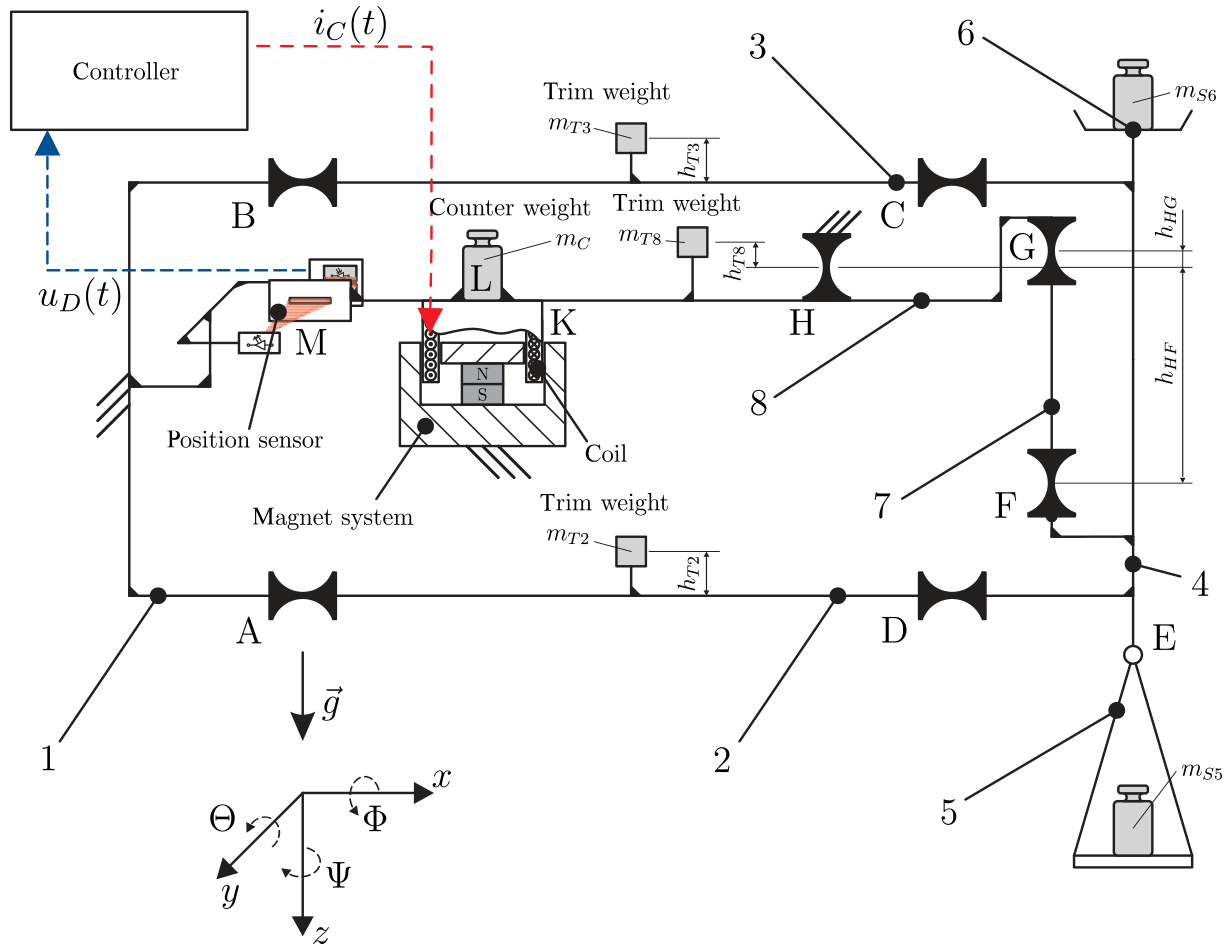
Figure 1Monolithic EMFC weighing cell with flexure hinges and typical joint orientation. 1 – base, 2 – lower lever, 3 – upper lever, 4 – load carrier, 5 – lower weighing pan, 6 – upper weighing pan, 7 – coupling element, 8 – transmission lever.
The sensitivity of the properties of the mechanism to manufacturing tolerances necessitates adjustment measures. This is common practice for all kinds of precision balances, but in contrast to equal arm beam balances (Conrady, 1922; Quinn, 1992; Speake, 1987), adjustment measures to EMFC-weighing cells are largely based on empirical knowledge and lack a comprehensive theory for design and adjustment. For EMFC-weighing cells few publications about the mechanical behavior can be found in the literature. In Marangoni et al. (2017) a static mechanical model of a monolithic weighing cell is derived. A novel extended adjustment concept is introduced that is capable of increasing the sensitivity with a simultaneous reduction of the tilt sensitivity to zero. The term that was coined for this adjustment state of equal arm beam balances is the autostatic state. In comparison to equal arm balances with autostatic adjustment (Conrady, 1922; Speake, 1987), this principle enables higher sensitivities which are only restricted by the adjustment resolution.
Extensive work on the dynamic behavior of EMFC-weighing cells and their optimization is presented in Hilbrunner et al. (2014). The modeling approach for the mechanical system of the weighing cell is varied, from a rigid body model in Baumgartl et al. (2010) to a three-dimensional finite element model in Hilbrunner et al. (2012). The periphery of the precision weighing cell, like different load changer concepts, is investigated in Hilbrunner et al. (2010).
The present work focuses on the static behavior of the mechanical structure of an EMFC-weighing cell. It aims to advance the understanding of the mechanical properties and their enhancement by means of targeted adjustments. This includes the improvement of the sensitivity of the overall system with a simultaneous reduction of its sensitivity to environmental disturbances.
The general scheme of an EMFC-weighing cell is presented in Fig. 1. The mechanism based on flexure hinges represents the core component of the weighing cell. The kinematic structure can either be described by a planar mechanism in the x–z plane or is extended in the third dimension (y direction) to a three-dimensional mechanism. The mechanical system can be divided into two main functional groups, the linear guiding system and the transmission lever. The linear guiding system is a monolithic realization of a parallelogram linkage including the base (1) and parts (2), (3) and (4); see Fig. 1. The weighing pans (5, 6) are attached to part (4). The gimbal mount (E) of the lower weighing pan (5) marks the determining difference to the fixed upper weighing pan (6). The transmission lever (8) is a simple beam suspended by a flexure hinge. These subsystems are coupled by a coupling element (7). The present modeling approach is restricted to planar systems and focuses on the mechanical system. Actuators, sensors and the controller are strongly simplified as forces or displacement constraints.
Employing the principle of electromagnetic force compensation, the mechanism of EMFC balances is quasi not deflected during operation. Residual deflections result from deviations of the position controller and elastic deformations of the structure itself. This excludes deflection-dependent geometrical nonlinearities and anelastic effects of the material to a large extent. Besides the intrinsic error sources, major disturbances arise from the environmental surroundings of the precision weighing device. Factors such as temperature, humidity, and air pressure are of high relevance, as well as turbulence and electric and magnetic fields (Gläser and Borys, 2009).
Quasi-static ground tilt and ground vibrations slightly move the base of the weighing cell (Kühnel et al., 2018) and result in measurement uncertainties that need to be addressed to allow more precise mass measurements. The error from ground tilts can be minimized for EMFC balances through adjustment of its mechanical system. For beam balances the autostatic adjustment is described in Conrady (1922) and Speake (1987). An extended concept for even higher sensitivities, while keeping the tilt influences close to zero, is introduced and investigated in (Darnieder et al., 2017; Marangoni et al., 2017) and is included in the mechanical model of this work.
The modeling of the monolithic mechanism of the EMFC-weighing cell is divided into two stages which can be differentiated by their modeling assumptions and applied methods. The first model, the linearized rigid body (RB) model, is based on strongly simplifying modeling assumptions; see Fig. 2. The thin flexure hinges are treated as idealized joints with a fixed rotational axis and a constant rotational stiffness. All other structural parts are rigid.
In contrast, the finite element analysis (FEA) is capable of considering elastic deformations of the mechanism; thus, non-ideal deflections of the flexure hinges are included. Thus, the comparison between the RB and FEA models reveals the limitations of the RB model and the influence of elastic deformations. The adjustment concept presented in Sect. 3.1 is intended to compensate for all effects considered in the models.
3.1 Adjustment concept and mechanical models
Weighing cells with high resolution rely on very thin flexure hinges as rotational joints to obtain a high sensitivity. The minimum thickness of the joints is technologically limited to about 50 µm (Bacher et al., 2002; Henein et al., 1999), which results in a rotational stiffness of about 0.018 Nm rad−1 for the geometrical dimensions presented in Table 2. Adjustments are essential since the stiffness of a manufactured and assembled weighing cell is highly sensitive to manufacturing and mounting deviations. Material properties like Young's modulus are generally not known precisely enough to enable a design without further adjustments (Smith and Chetwynd, 1992). Consequently, weighing cells require adjustments prior to their application. The adjustment measures are intended to set a specific value for the mechanical stiffness to define the sensitivity of the sensor system. This has to be accomplished with a simultaneous reduction of the sensitivity to ground tilt.
Figure 2 presents the RB model of the weighing cell. The parameters incorporated in the adjustment concept are highlighted in blue.
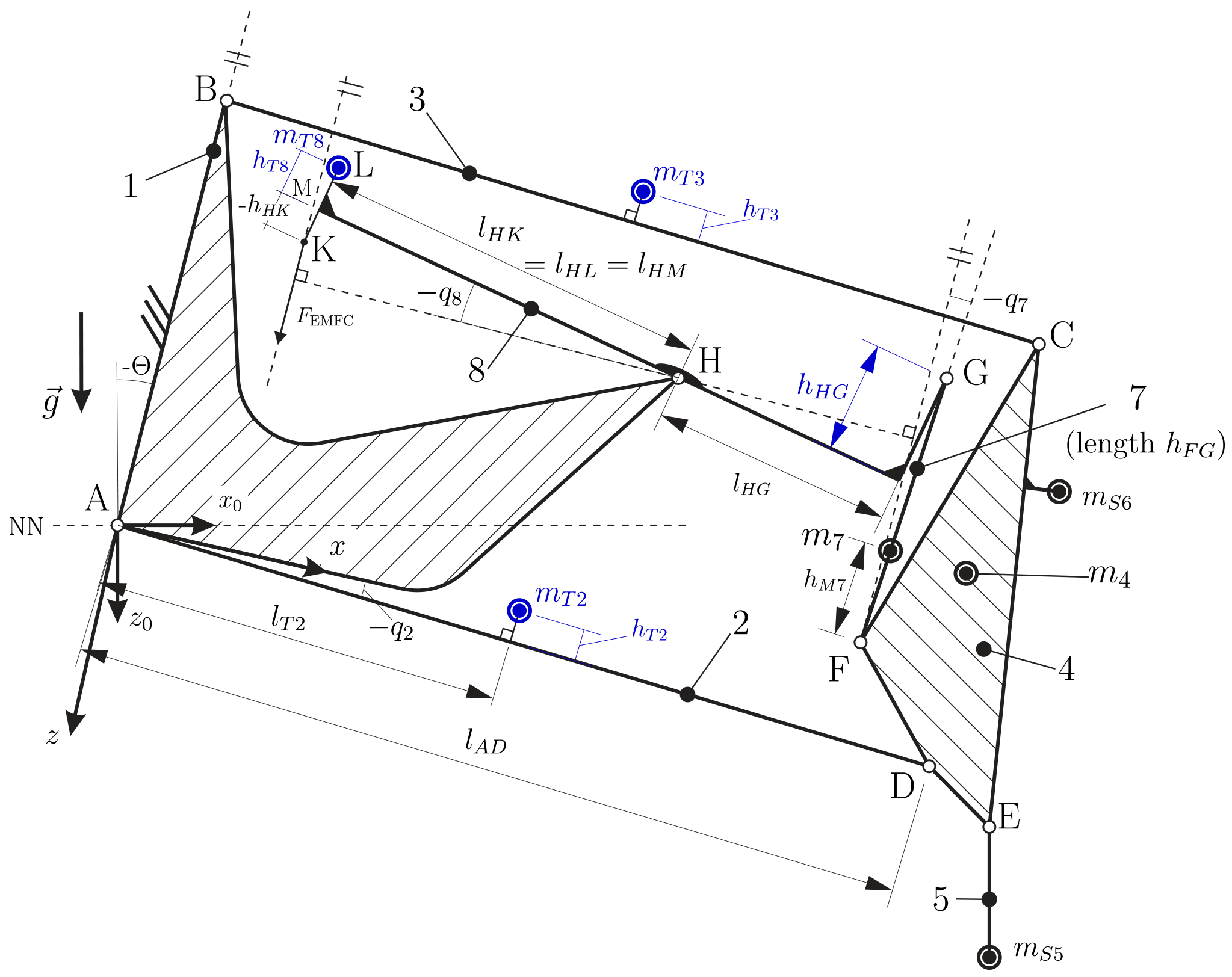
Figure 2Rigid body model of the deflected weighing cell (q8) with a tilted base (body 1) with respect to g (Θ). Body 6 is a sample weight on the upper weighing pan (mS6) rigidly coupled to body 4. The three adjustable parameters hT2=hT3, hT8 and hHG are highlighted in blue.
The adjustment measures include the adjustment of the centers of mass of parts in the kinematic system by displacing small trim weights (hT2=hT3, hT8). In addition, the vertical distance hHG between joints H and G is introduced to destabilize the mechanism without an increase in tilt sensitivity.
Two modeling stages are used to investigate the behavior of the weighing cell structure. The mechanical models of the weighing cell include all adjustment parameters (see Fig. 2) to determine their optimal values. A RB model with idealized rotational joint is derived in the first modeling stage.
3.2 Rigid body model
The mechanical model of the monolithic mechanism is simplified based on the following assumptions: the compliant mechanism has concentrated compliance (semi-circular flexure hinges). All other parts are modeled as rigid bodies with lumped masses. The flexure hinges are modeled as perfect rotational joints with a fixed rotational axis and a constant rotational stiffness. All flexure hinges in the mechanism are modeled with equal geometric parameters and rotational stiffness. Frictional losses in the joints are not considered. The coupling element between the subsystems is modeled as a deflection-dependent transmission ratio between the deflection angles q2 (linear guide) and q8 (transmission lever); see Fig. 2. With this constraint, the degree of freedom of the RB mechanism is f=1. The system equation for the static equilibrium is derived using Lagrange's equations of the second kind:
Here, j represents the number of the independent system variables, Qj the generalized forces and f the degree of freedom of the mechanical system. Angle q8 of the transmission lever is designated as the independent system variable. The system is conservative, except for the force applied to the transmission lever (QEMFC):
For a quasi-static consideration, the kinetic energy T is zero and Eq. (2) simplifies to
The potential energy U of the weighing cell is formulated in with the position vectors . The potential energy Um of the point masses and the elastic potential Uel of the joints yields
To treat the system in a straightforward manner, a simplification concerning the kinematic coupling between the two subsystems is introduced. For this purpose a kinematically equivalent system of the weighing cell is derived in Fig. 3. Since the motion paths of C, D and F are equal, the kinematic of the parallelogram guide can be represented by the lower lever only. For q8→0 the velocity vectors of points D and G become equal, which means that points D and G travel the same vertical distance; see Fig. 3. This approximation is justified, since the weighing cell is practically not deflected () during its operation.

Hence, δD is equated with δG, resulting in Eq. (7).
The trigonometric functions in Eq. (7) can be replaced by their respective Maclaurin series truncated after the second term: . This results in Eq. (8) for the transmission ratio i of the subsystems transmission lever and linear guide:
The angle of the coupling element q7 is approximated by
Equation (3) then yields
The generalized force for the electromagnetic force of the moving coil actuator FEMFC is given by
The linearization of Eq. (10) leads to a rather simple equation that can be sorted according to q8 and Θ by partial differentiation. This clear structure provides a good overview of the main factors that influence the stiffness and the tilt sensitivity. It becomes obvious that a combination of the highlighted adjustment parameters in Fig. 2 can be used to minimize stiffness C and tilt sensitivity D. The optimal system configuration is fulfilled if the following conditions with are met:
The linear equation system Eqs. (12) to (14) includes the relevant properties of the weighing cell, stiffness C, tilt sensitivity D and equilibrium condition of the non-deflected system – B. The sign of the tilt sensitivity terms in Eq. (13) corresponds to the sign of an equivalent mass change ΔmS5,ΔmS6 on the weighing pans. A weighing cell for use in a mass comparator should be designed to comply with the solution of the equation system.
The tilt sensitivity D of the rigid body model in Eq. (13) covers the effect of eccentric mass points relative to the rotational centers of the bodies. The comparison with the results from the geometrically nonlinear FEA model suggests that elastic deformation leads to additional effects.
3.3 Finite element model
The FEA model is created using ANSYS Mechanical APDL®. The structural parts are meshed with SOLID186 elements based on quadratic displacement functions. The structure consists of several components that are linked by flexure hinges.
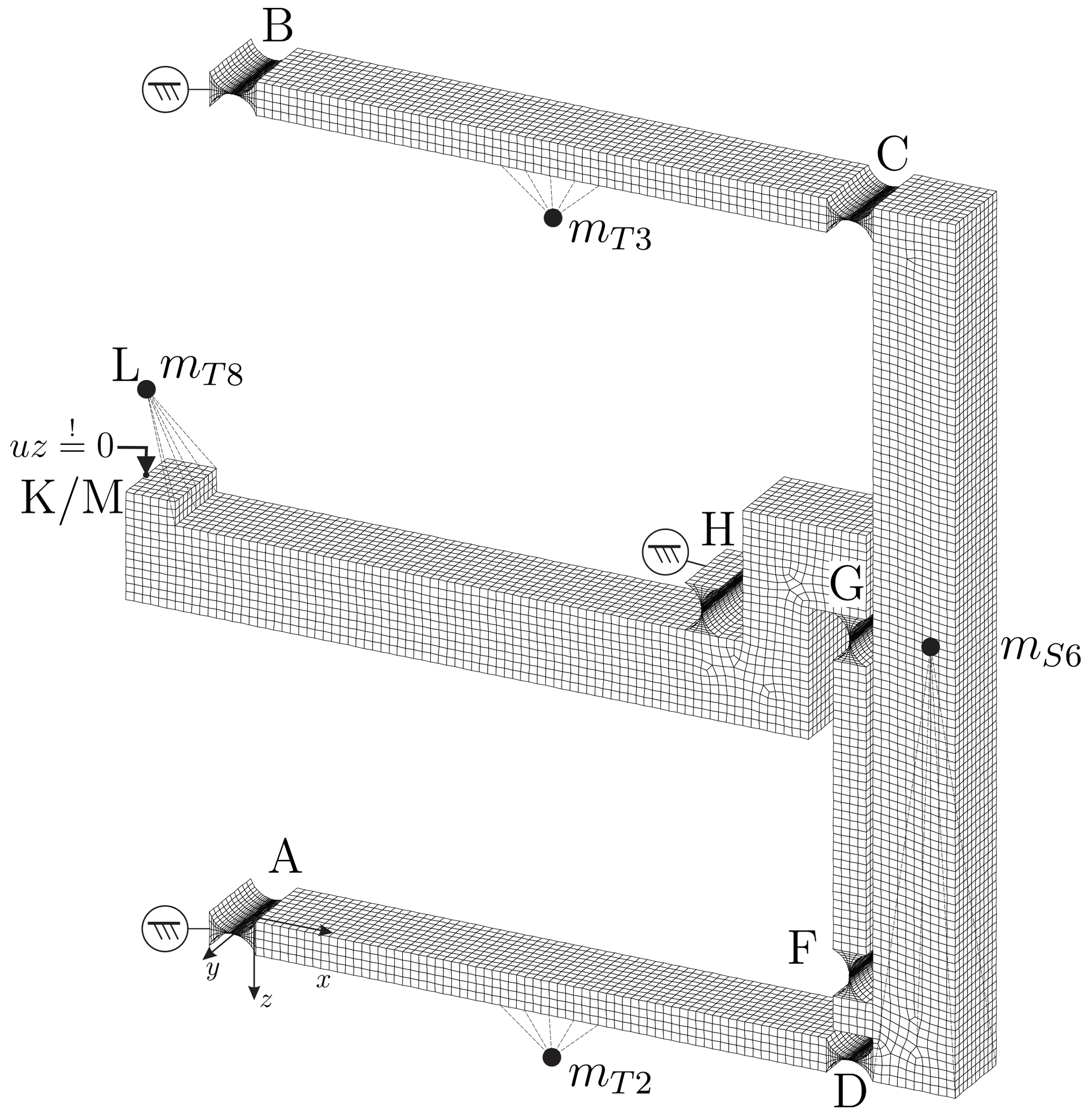
Figure 4Finite element model of the weighing cell structure with flexure hinges. The point masses attached to the structure are displayed as •. The contact with the surface nodes is indicated by dashed lines. The displacement constraint is applied to a pilot node connected to the left side of the transmission lever (8) by multi-point constraints.
The volume is assigned with linear elastic material properties of aluminum alloy, which is commonly in use for precision weighing cells (Gläser and Borys, 2009). The FEA model is chosen to be three-dimensional as shown in Fig. 4. The geometrical parameters are adopted from Table 2. In the FEA model, the base of the weighing cell is fixed and g is rotated about the y axis to determine the tilt sensitivity D. The sample weight (mS6), the mass (mT8) and the lever masses (mT2, mT3) are modeled as point masses coupled by contact elements using internal multi-point constraints. The density of the material is set to zero to keep the FEA model comparable to the rigid body model. A z displacement constraint is exerted on a pilot node that is attached to the left end of the transmission lever. This way an ideal position control by the EMFC system is modeled. The required force to keep the balance in static equilibrium is given by the reaction force of the constrained node (FEMFC).
Table 2Model parameters.
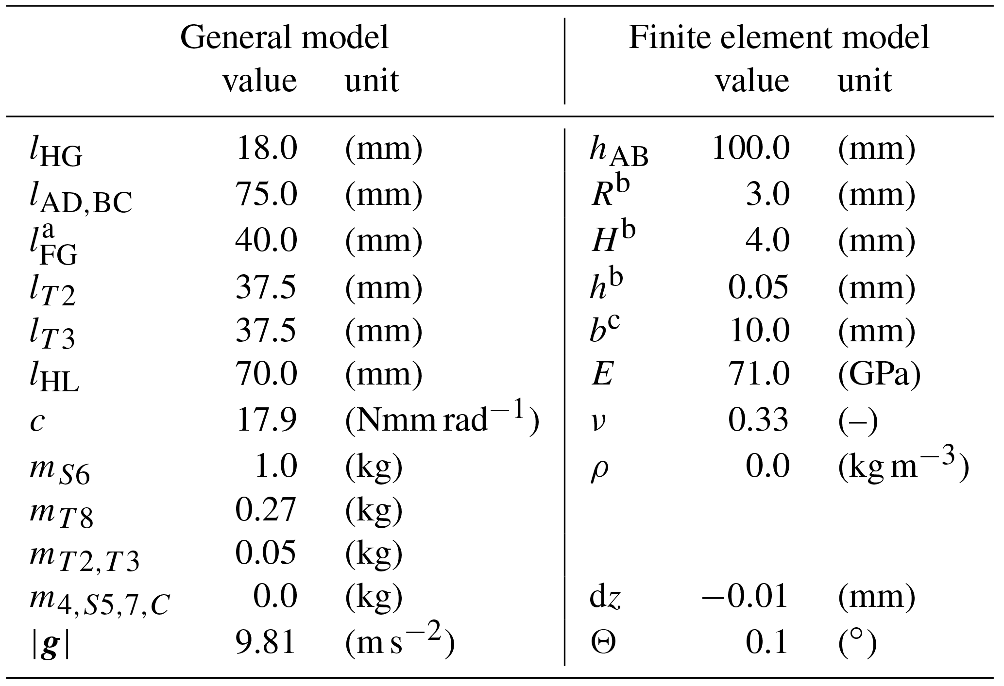
a For hHG=0. b Flexure hinge: R radius, H total height, h minimal notch height. c Depth of the structure.
The setup of the model enables the alteration of several parameters. The most influential parameters for the properties of the structure with respect to its application in precision weighing are the centers of rotation and centers of mass. Their influence on the properties of the total structure is determined by parametric studies.
Figure 4 shows the mesh of the weighing cell structure with the loading condition of mS6=1 kg and mass on the transmission lever of mT8=0.27 kg. The displacement constraint in the z direction is applied to the left end on the transmission lever with no vertical distance to the initial position of joint H. For the determination of the stiffness, the constrained node is slightly displaced in the z direction by mm. The difference of the reaction forces is used to calculate the stiffness C of the monolithic mechanism close to its zero position. The model considers geometric nonlinearities with respect to the large rotations of the structure.
The computational results from the modeling approaches are presented and compared. From this juxtaposition, consequences for the applicability ranges of linear model equations are derived.
4.1 Limitation of the derived rigid body model
Investigations on flexure hinges reveal that flexures do not show pure rotations due to a shift of the rotational axis during their deflection (Linß et al., 2017). EMFC-weighing cells are operated very closely around the zero deflection position, leading to the assumption that these effects are negligible. Apart from this, parasitic force components on the hinges may have a pronounced effect on the characteristic of the total mechanism. Especially for a non-perfectly aligned weighing cell (Θ≠0), the lateral force components result in an s-shaped deformation of the hinges and additional parasitic torques on the connected parts. This effect was considered for the development of the FB-2 equal arm balance of BIPM (Quinn et al., 1986; Speake, 1987).
The joint orientation, which proves to be relevant in other fields (Gräser et al., 2017), is completely neglected in the rigid body model. Due to the pronounced directional dependence of the compliance in the spatial directions, this is a relevant aspect especially for joints A to D in the case of additional trim weights on the levers (mT2, mT3).
Another aspect is the change in rotational stiffness of the joint due to the static axial load (Eastman, 1937). This is especially relevant for joint H that suspends the largest amount of the total mass of the structure, including the sample weight on the weighing pan mS6 and the mass mT8.
The geometrically nonlinear FEA model reveals the limited validity of the linearized rigid body model. This can be shown in the case of the modeling of the coupling element. According to the model Eq. (12), the adjustment of hHG has a pronounced and linear effect on the stiffness characteristic of the system. This is valid only for a certain range and for a sufficient length of the coupling element hFG, as the parameter variation within the FEA model in Fig. 5 shows.
.
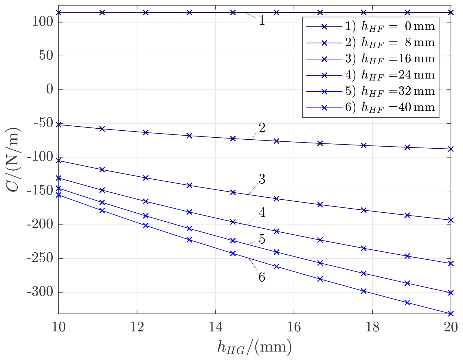
Figure 5The destabilizing effect of the hHG-adjustment decays with a decreasing distance between joint F and joint H. In case hHF becomes negative, the stiffness even increases slightly. For hHG and hHF, see Fig. 1
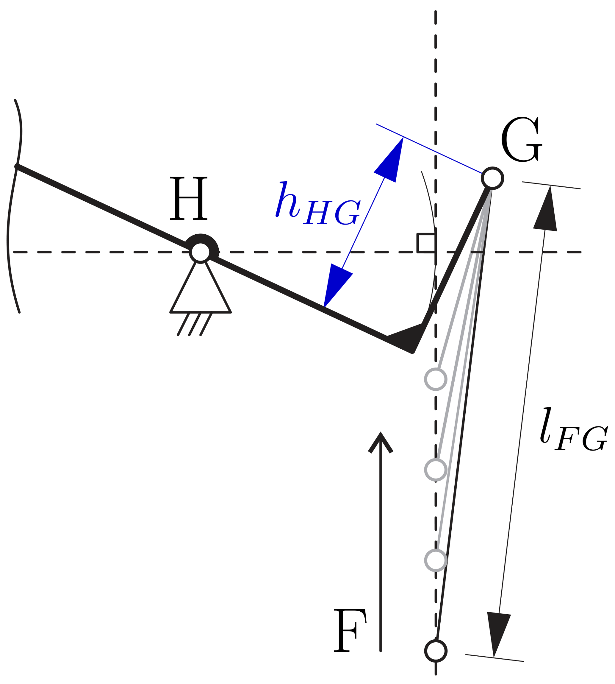
Figure 6Visualization of the angles of the coupling element for a deflected state of the weighing cell. The adjustment parameter hHG is kept constant. If joint F is shifted upwards, the stiffness reduction effect of the parameter hHG is decreased.
In Fig. 6 one can observe how the position of joint F and thus the length of the coupling element hFG changes the angle of the coupling element in a deflection state of the weighing cell. For the effect of stiffness compensation it is advantageous if the joint F is located well below the center of rotation of joint H. It can be observed that for a specific z position of joint F close to the z position of point H the destabilizing effect of hHG>0 is no longer present. This is due to the angular deflection of the coupling element and the resulting angular force on joint G on the transmission lever; see Fig. 6.
4.2 Compensation of restoring forces
The compensation of restoring forces of the compliant mechanism can be equated with the destabilization of the system. The stiffness C decreases and thus the stability of the mechanism is reduced. As Eq. (12) shows, there are two options available to compensate for the restoring forces. The vertical shift of the center of mass of a part above the respective center of rotation is one option, with the downside of increasing the tilt sensitivity. As an alternative, the height of the adjoining hinges on the transmission lever can be adjusted vertically with respect to its center of rotation (e.g., hHG). This adjustment leads to a minor change in tilt sensitivity but a major change in the overall stiffness; see Fig. 7.
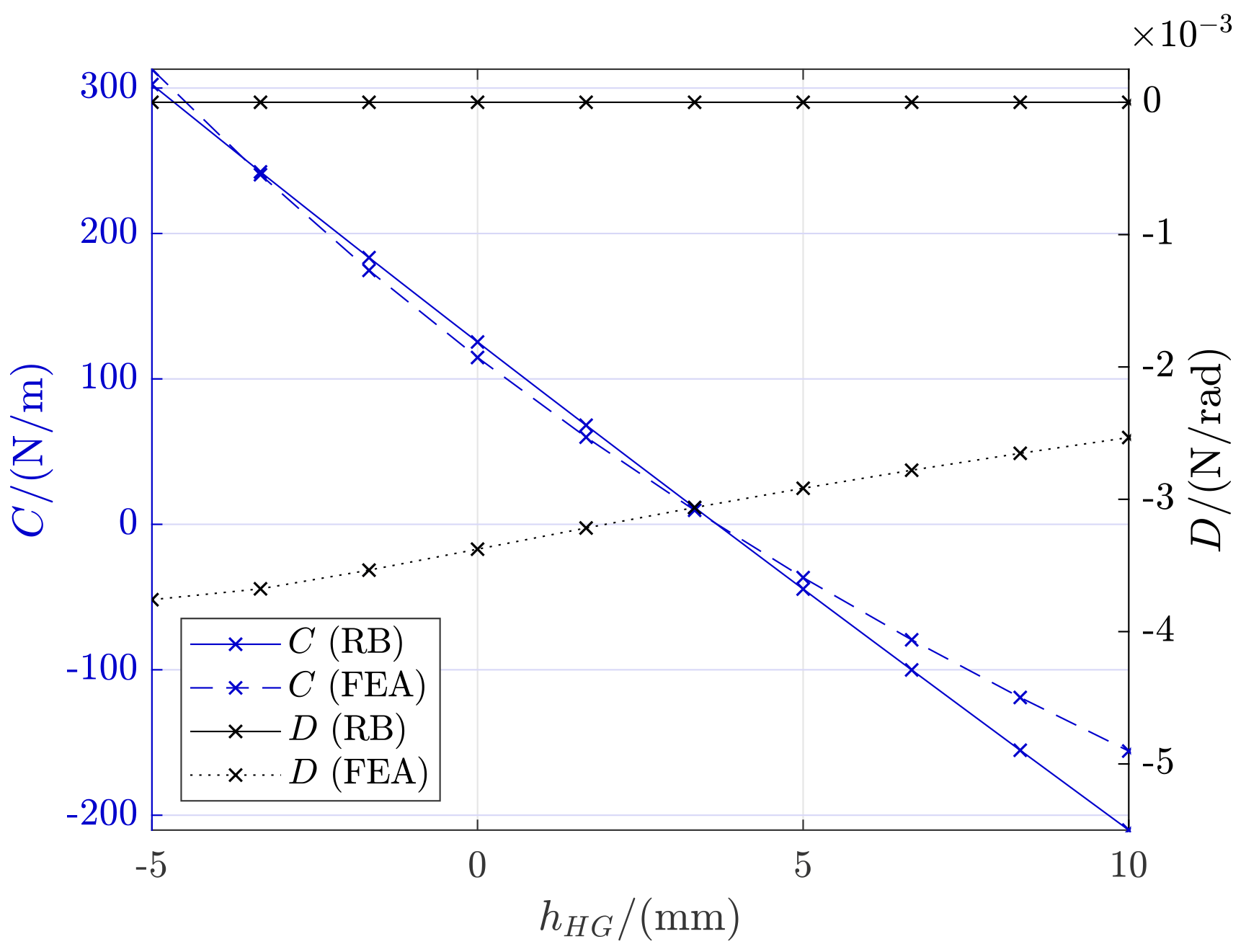
Figure 7Variation of hHG in combination with a probe mass of mS6=1 kg compensates for the stiffness from restoring forces of the flexure hinges. The comparison with the rigid body model shows that the linearization is an approximation of the true behavior. This is especially relevant if hHF approaches zero; see Fig. 5.
It involves the downside of being dependent on the mass of the sample weight that is placed on the weighing pan, as can be observed in Fig. 8. Depending on mS6, hHG can be an influential adjustment parameter to minimize the stiffness in a mass comparator with a close to constant loading situation (Speake, 1987). In the case of a nominal load of 1 kg, an adjustment of mm compensates for the entire stiffness of the weighing cell.

Figure 8Linear load dependency of the stiffness C due to the hHG adjustment restricts the applicability of the adjustment to mass comparators with small weighing ranges.
4.3 Adjustment to minimize stiffness and tilt sensitivity
The parameter variation is limited to the highlighted adjustment parameters in Fig. 2. The adjustment parameter hHG has to be chosen prior to the manufacturing of the weighing cell, whereas the adjustments hT2, hT3 and hT8 can be realized by additional trim weights. The following adjustment strategy of three steps is used to find the optimum in the three-dimensional parameter space.
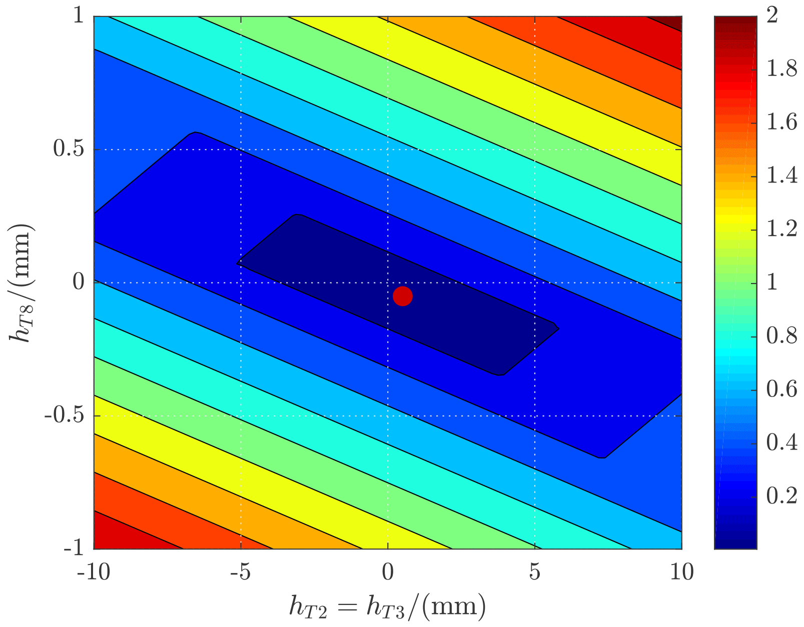
Figure 9FEA results of the function in step 3 with mm (matrices for C and D normalized). The red dot indicates the optimal adjustment with mm and mm.
-
adjustment of hHG to compensate the restoring forces (see the zero crossing of C in Fig. 7):
; -
parameter variation of hT2=hT3 and hT8;
approximation of
and ; -
determine minimum:
→ , , .
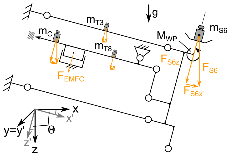
The optimal adjustment configuration of the weighing cell is shown in Fig. 9 (red dot). It is the minimum of the function . The enhancement of the properties' stiffness and tilt sensitivity is presented in Table 3. The reader is urged to rather place the focus on the proof of principle than on absolute values for the adjustment parameters, since they are dependent on a large number of parameters.
Table 3Adjustments of the FEA model.
* Note that location of the optimum () is dependent on the choice of .
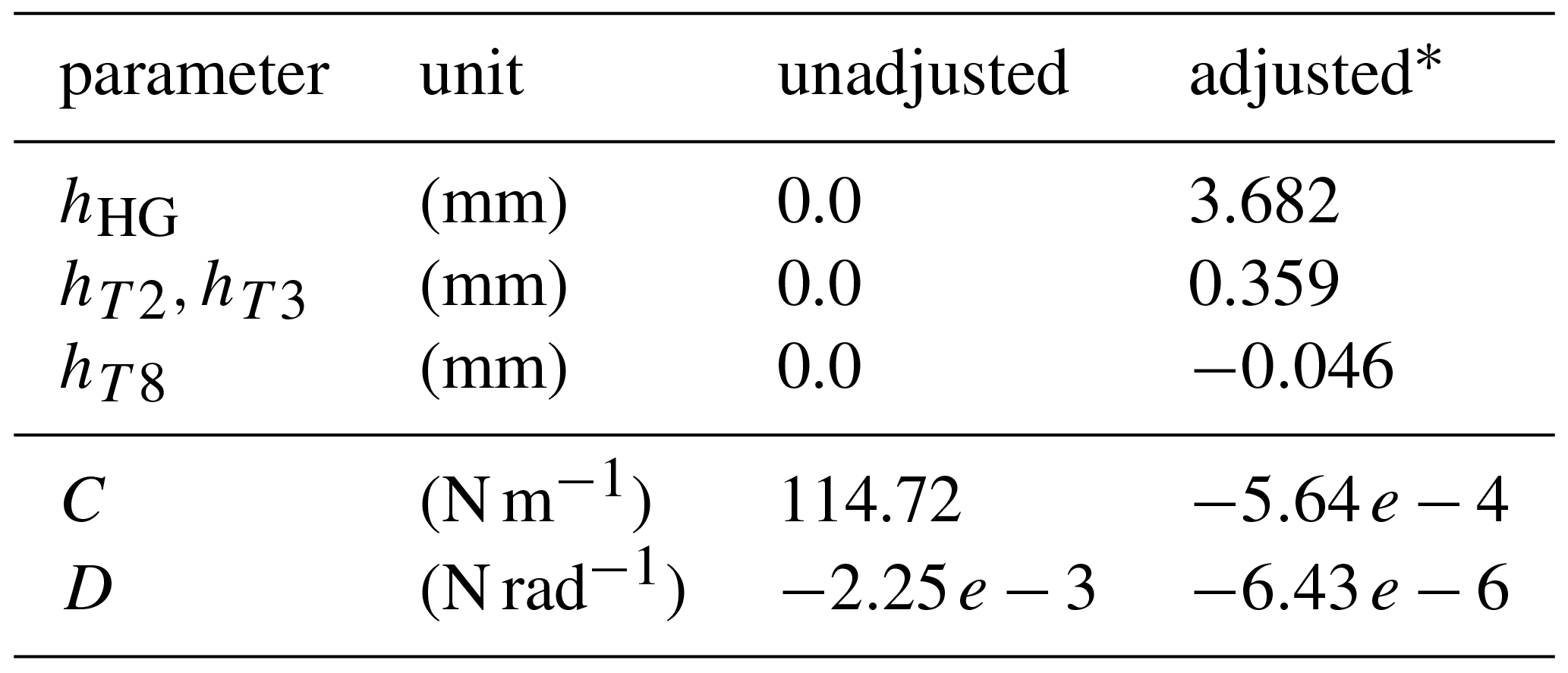
For the experimental setup, the weighing cell of commercially available mass comparator MCM1005 was set up on top of the precision tilt table (Kühnel et al., 2014) (see Fig. 10). The setup is placed on a weighing stone with its own, separated foundation in the basement of the building. The tilt table can tilt both horizontal axes independently by ±17.6 mrad with a reproducibility of 0.351 µrad (Kühnel et al., 2014).
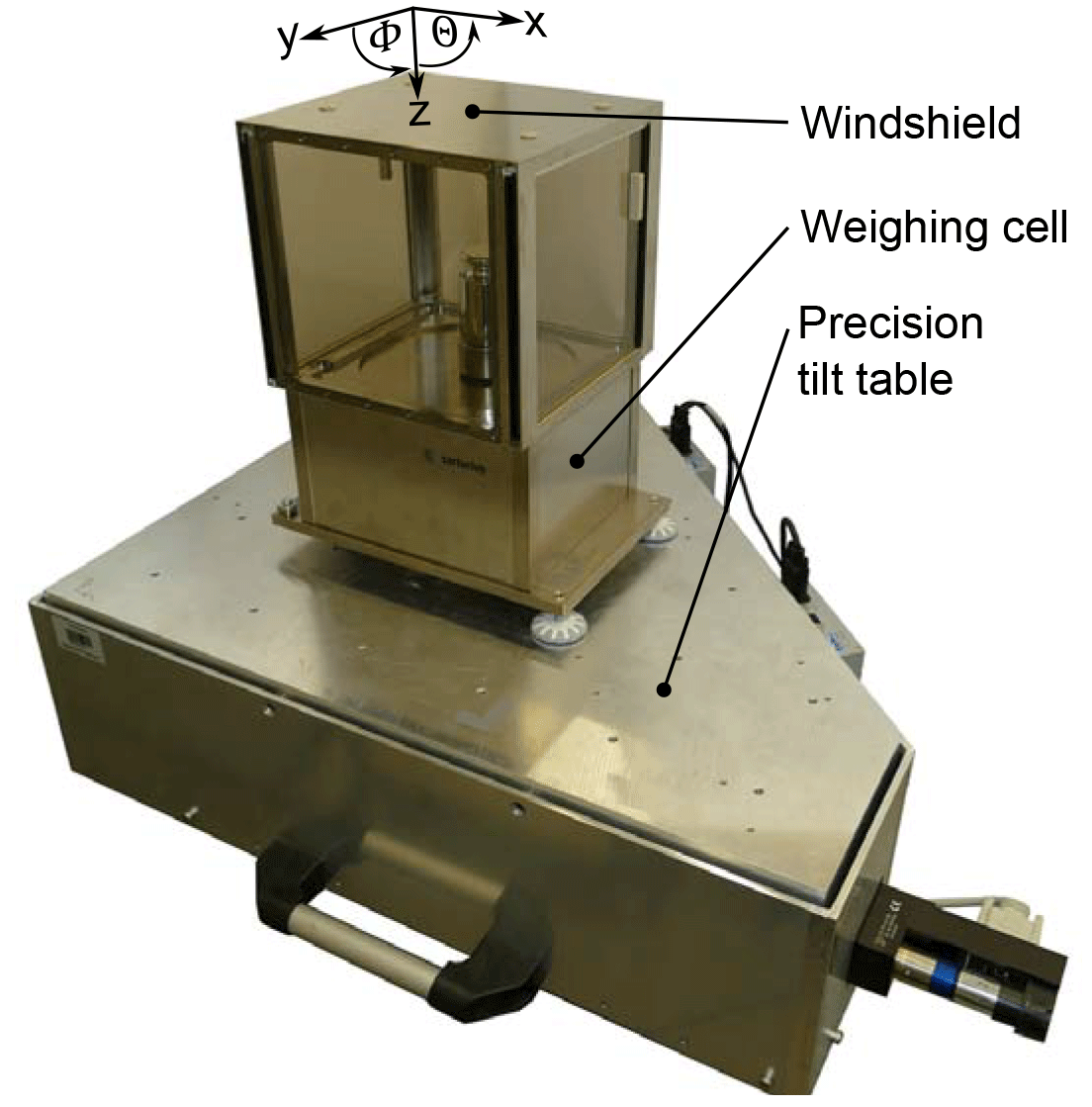
Figure 10Experimental setup for the determination of tilt sensitivities with the EMFC-weighing cell based on the mass comparator MCM1005.
The measurement results of weighing systems are sensitive for tilt. If the weighing cell is not horizontally aligned, as shown in Fig. 11, the gravity vector g is not parallel to the z axis of the weighing cell. This results in a separation of the force FS6 into its spatial components, of which only the z component is measured. This leads to a cosine deviation of the weighing result for both tilt axes and proportional to the force of the actuator (Darnieder et al., 2018):
The cosine deviation in Eq. (15) is overlaid by a larger linear component for tilts about the y axis (Θ) depending on the vertical distance of the respective centers of mass to their center of rotation. The additional deviation through tilt about the x axis (Φ) is unknown. If the structure was perfectly symmetric, without material defects, elastic deformations and manufacturing deviations, there would be no additional influence. In theory the parallel guide prevents movements in y direction or tilts about the x axis. Due to imperfections in the real mechanical structure and elastic deformations, tiltings of the base induce measurement uncertainties.
5.1 Experimental results
After calibration of the weighing cell by use of an interferometer and an E2-calibration weight, the setup is prepared for the measurement of tilt sensitivities. For a first overview the controller, operating in normal mode, keeps the transmission lever in its undeflected position while the tilt table approaches different stages of tilt. Once at the beginning, in the middle and at the end of each measurement the tilt table is returned to its zero position (), to avoid influences of linear drift. Once a certain tilt stage is reached and settled, the table holds the position in a quasistatic state to determine the tilt reaction. For the fist measurement, the weighing cell is tilted in several steps between ±15 mrad independently for both axes exemplarily shown in Figs. 12 and 13.

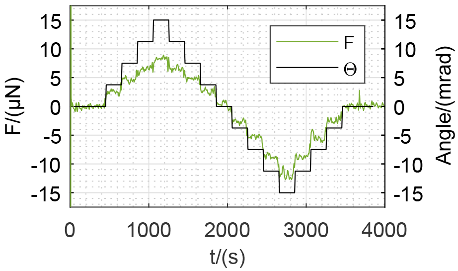
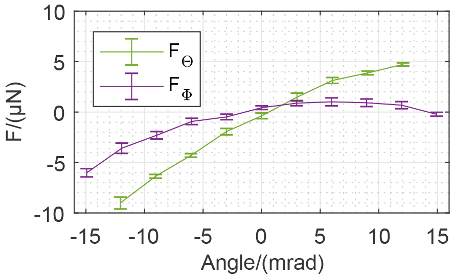
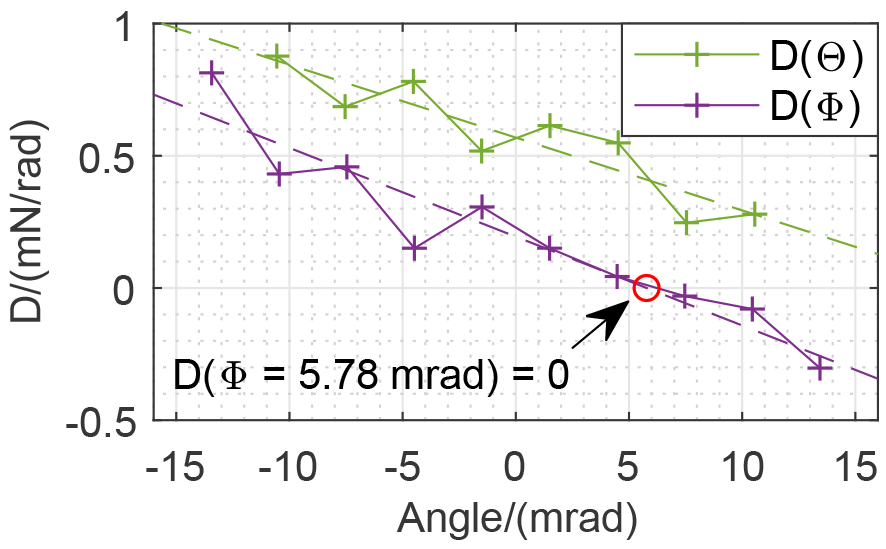
The results of the measurements are calculated based on the continuous measurement signal of the weighing cell during the static states of the tilt table. The measured tilt reactions are correlated with the respective tilt angles as presented in Fig. 14. The results of the investigation are in accordance with the theoretical behavior of the FEA model described earlier. As expected, there is a linear influence overlapped by the cosine deviation concerning the signal during tilt of the y axis (Θ). Tilting about the x axis (Φ) shows the cosine deviation in addition to a linear dependence with unknown origin. The results of the investigation provide tilt sensitivities (D) about the zero position for both horizontal axes:
For larger angles up to ( mrad) the tilt sensitivities were also calculated and are presented in Fig. 15. It shows a linear correlation between tilt angle and tilt sensitivity for both axes.
With this effective and automated method to measure the tilt dependencies in predefined tilt positions, the influence of adjusting parameters such as additional trim weights on the upper lever (3) or the transmission lever (8) can be investigated in dependence of tilt.
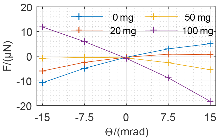
Figure 16Influence of the trim weight (mT8) on the tilt sensitivity of the weighing cell close to DΘ=0.
The investigation was continued by adding small trim weights on the transmission lever (as shown in Fig. 11). Therefore, the method for measuring the tilt sensitivity in dependence of the tilt angle was repeated for different trim weights (mT3 and mT8; see Fig. 2 and Table 1) while the conditions in the laboratory were kept constant. The measurements show that the tilt sensitivity of the weighing cell can be influenced as presented in Fig. 16. Commercially available weighing cells are already trimmed to minimize the influence of tilt on the measurements, so for the first investigation small E2 weights from 20 to 100 mg were used for measurements of the influence of mT8 close to DΘ=0 (compare Fig. 16). To cover up a larger range and for a better comparison of the measurements with the model, E2 weights up to 5 g were placed on the transmission lever. Figure 17 shows that the results are in correspondence to the model.

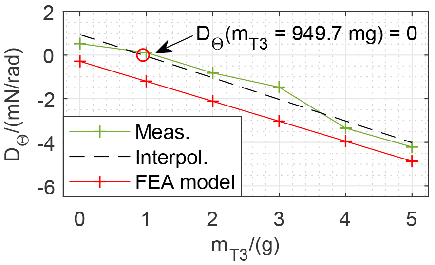
Figure 18Influence of the trim weight at the lever (mT3) on the tilt sensitivity of the weighing cell.
The influence of trim weights on tilt sensitivity shows a linear relationship with DΘ=0 for mT8=64.4 mg. The same method was applied for measurements of the influence of trim weights on the upper lever (3) (results shown in Fig. 18). Here, the influence is estimated to be clearly smaller due to the ratio of the transmission lever (compare Fig. 11). The advantage is a higher resolution in adjusting the tilt sensitivity . Here the influences of trim weights have a linear relationship as expected. For DΘ=0 the mass mT3 is approximated to 949.7 mg.
Modeling aspects of high-precision monolithic weighing cells based on quasi-static mechanical models are discussed. A linear equation system is introduced, presenting the most relevant mechanical properties of the weighing cell at a glance. The solution of the equation system, involving adjustable parameters, provides a foundation for a preliminary design definition of a weighing cell based on geometry, lumped masses and joint stiffness.
The comparison with a geometric nonlinear FEA model reveals the limitations of the linear RB model and stresses the need for advanced models to refine the design. The two models show good correspondence in terms of stiffness in the relevant range and for a sufficient length of the coupling element (hFG). The load dependency of the stiffness C(mS6) for hHG≠0 but also for hHG=0 was shown in the FEA model. The latter clearly shows the influence of the elastic deformations within the compliant mechanism, which is relevant for the tilt behavior as well. With all adjustment parameters set to zero in the models, the rigid body model predicts zero tilt reactions, whereas the FEA model reveals non-zero tilt reactions. This suggests that parasitic deformations of the compliant mechanism are a major source of tilt reactions. They occur in the assumed rigid connective parts and predominantly in the thin flexure hinges. By considering these elements as beams, the rigid body model can be extended and improved. A further influencing quantity is given by the initial deflection of the parallelogram linkage (q8=0, q2>0) due to the elongation of the coupling element and the bending deformation of the transmission lever. This results in an increase in sensitivity to lateral force components (e.g., tilt, pan swing Quinn, 1992).
All the mentioned effects are covered by the FEA model and, as Sect. 4.3 shows, stiffness and tilt sensitivity can be minimized by adjustment. Using the geometrically nonlinear FEA model, it is concluded that very low values for the stiffness as well as the tilt sensitivity can be obtained by combining the adjustments. Compared to the non-adjusted weighing cell, the stiffness and tilt sensitivity can be reduced significantly. Parasitic torques resulting from elastic deformations can thus be compensated by the presented adjustments as long as the deflections of the structure stay small. This way the sensitivity of monolithic weighing cells can be significantly increased while simultaneously reducing the tilt sensitivity. The conducted measurements with additional trim weights in different positions verify the results of the FEA model with small deviations. This is due to the missing precise knowledge of the exact locations of the centers of mass in the commercial weighing cell. The viability of the adjustment concept is confirmed in principle. The true potential of the presented adjustment concept will be revealed by future experiments with self-developed monolithic prototype weighing cells. It is expected that effects like out-of-plane loads, manufacturing deviations and anelastic material behavior will be further limiting factors for the performance. These topics as well as further refinement of the mechanical models and a consideration of dynamic effects are part of the ongoing work.
The underlying measurement data and software codes are not publicly available and can be requested from the authors if required.
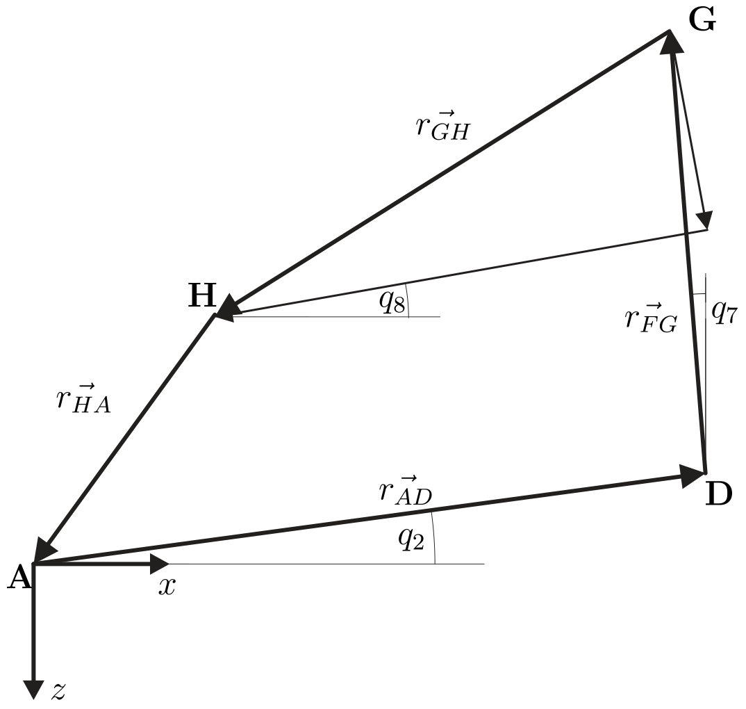
Figure A1Closed vector loop derived from Fig. 3 as the basis for the derivation of the nonlinear equations.
The simplified kinematic structure shown in Fig. 3 can be analyzed by the formulation of a closed vector loop along the bodies of the mechanism; see Fig. A1 and Eq. (A1).
The resulting nonlinear equations for the spatial directions are presented in Eqs. (A2) and (A3).
The equation system can be solved numerically to compare the solution to the proposed transmission ratio presented in this paper – Eq. (8). The deviation is calculated in the relevant range ( mm; ). The relative error due to the introduced simplification at the coupling amounts to a maximum of 0.017 %. In view of even smaller deflection angles during operation, the use of the simplified equation is justified.
The mesh of the thin flexure hinges in the FEA model is crucial for the overall accuracy of the computation covering the entire mechanism. The convergence in terms of bending stress is determined for a single flexure hinge.
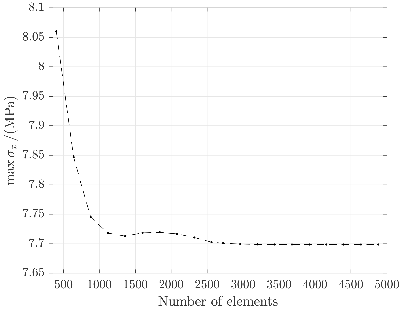
Figure B1 reveals that the mesh is sufficiently refined with an element number of 3280 for each flexure hinge. This mesh configuration is used for the flexure hinges throughout the FEA calculations.
MD and MP wrote the initial draft of the paper. MD elaborated the mechanical models, whereas MP conducted the measurements. TF and RT conceptualized the research and raised the funds. TF, RT, RW and LZ were involved in reviewing and editing the paper.
The authors declare that they have no conflict of interest.
The authors would like to thank the German Research Foundation (DFG) for the
financial support of the project with grant nos. TH 845/7-1 and FR 2779/6-1.
Edited by: Bernhard Jakoby
Reviewed by: three anonymous referees
Bacher, J.-P., Joseph, C., and Clavel, R.: Flexures for high precision robotics, Ind. Robot, 29, 349–353, https://doi.org/10.1108/01439910210432911, 2002. a
Baumann, H., Eichenberger, A., Cosandier, F., Jeckelmann, B., Clavel, R., Reber, D., and Tommasini, D.: Design of the new METAS watt balance experiment Mark II, Metrologia, 50, 235–242, https://doi.org/10.1088/0026-1394/50/3/235, 2013. a
Baumgartl, H., Hilbrunner, F., Fröhlich, T., and Jäger, G.: Parametric mechatronic model of a load cell with electromagnetic force compensation, IMEKO TC3 & TC5 & TC22 International Conference: [IMEKO 2010 held in Pattaya, Thailand from 21 to 25 November 2010; Metrology in modern context], 29–32, 2010. a
Conrady, A. E.: A Study of the Balance, P. R. Soc. A, 101, 211–224, 1922. a, b, c
Darnieder, M., Theska, R., Fröhlich, T., Pabst, M., Wenig, R., and Hilbrunner, F.: Design of high-precision weighing cells based on static analysis, Engineering for a changing world: 59th IWK, Ilmenau Scientific Colloquium, Technische Universität Ilmenau, 11–15 September 2017: proceedings, 2017. a
Darnieder, M., Fröhlich, T., and Theska, R.: Tilt sensitivity modeling of a monolithic weighing cell structure, in: Interdisciplinary Applications of Kinematics, edited by: Kecskeméthy, A. and Geu Flores, F., Springer International Publishing, 2018. a
Eastman, F. S.: The Design of Flexure Pivots, J. Aeronaut. Sci., 5, 16–21, https://doi.org/10.2514/8.499, 1937. a
Gläser, M. and Borys, M.: Precision mass measurements, Rep. Prog. Phys., 72, 126101, https://doi.org/10.1088/0034-4885/72/12/126101, 2009. a, b, c
Gräser, P., Linß, S., Zentner, L., and Theska, R.: On the influence of the flexure hinge orientation in planar compliant mechanisms for ultra-precision applications, Engineering for a changing world: 59th IWK, Ilmenau Scientific Colloquium, Technische Universität Ilmenau, 11–15 September 2017: proceedings, 2017. a
Henein, S., Aymon, C., Bottinelli, S., and Clavel, R.: Fatigue failure of thin wire-electrodischarge-machined flexure hinges, in: Proc. SPIE 3834, Microrobotics and Microassembly, edited by: Nelson, B. J. and Breguet, J.-M., SPIE Proceedings, 110–121, SPIE, https://doi.org/10.1117/12.357815, 1999. a
Hilbrunner, F., Baumgartl, H., Fröhlich, T., and Jäger, G.: Comparison of different load changers for EMFC-balances, IMEKO TC3 & TC5 & TC22 International Conference: [IMEKO 2010 held in Pattaya, Thailand from 21st to 25th November 2010; Metrology in modern context], 65–68, 2010. a
Hilbrunner, F., Baumgartl, H., Petzold, R., Fröhlich, T., and Jäger, G.: Investigation on the impedance-frequency-response for a dynamic behaviour description of elecromagnetic force compensated load-cells, Proceedings of XX IMEKO World Congress: 9–14 September 2012, Bexco, Busan, Republic of Korea, 2012. a
Hilbrunner, F., Weis, H., and Fröhlich, T.: Parameterization and optimisation of EMC balances based on the frequency response of the impedance, Measurement, 51, 349–355, https://doi.org/10.1016/j.measurement.2014.01.032, 2014. a
Hilbrunner, F., Rahneberg, I., and Fröhlich, T.: Watt balance with lever transmission based on commercial EMFC load cell, Tech. Mess., 85, 658–679, https://doi.org/10.1515/teme-2017-0065, 2017. a
Kochsiek, M. and Gläser, M.: Comprehensive mass metrology, Wiley-VCH, Weinheim and New York, https://doi.org/10.1002/3527602992, 2000. a
Kühnel, M., Rivero, M., Diethold, C., Hilbrunner, F., and Fröhlich, T.: Dual axis tiltmeter with nanorad resolution based on commercial force compensation weigh cells, Shaping the future by engineering: 58th IWK, Ilmenau Scientific Colloquium, Technische Universität Ilmenau, 8–12 September 2014; proceedings, 2014. a, b
Kühnel, M., Fern, F., and Fröhlich, T.: Novel monolithic pendulum tiltmeter with Nanorad resolution, Tech. Mess., 85, 244–251, https://doi.org/10.1515/teme-2017-0097, 2018. a
Linß, S., Schorr, P., and Zentner, L.: General design equations for the rotational stiffness, maximal angular deflection and rotational precision of various notch flexure hinges, Mech. Sci., 8, 29–49, https://doi.org/10.5194/ms-8-29-2017, 2017. a
Marangoni, R. R., Rahneberg, I., Hilbrunner, F., Theska, R., and Fröhlich, T.: Analysis of weighing cells based on the principle of electromagnetic force compensation, Meas. Sci. Technol., 28, 75101, https://doi.org/10.1088/1361-6501/aa6bcd, 2017. a, b
Quinn, T. J.: The beam balance as an instrument for very precise weighing, Meas. Sci. Technol., 3, 141–159, https://doi.org/10.1088/0957-0233/3/2/001, 1992. a, b
Quinn, T. J., Speake, C. C., and Davis, R. S.: A 1 kg Mass Comparator Using Flexure-Strip Suspensions: Preliminary Results, Metrologia, 23, 87, https://doi.org/10.1088/0026-1394/23/2/002, 1986. a
Richard, P., Fang, H., and Davis, R.: Foundation for the redefinition of the kilogram, Metrologia, 53, A6–A11, https://doi.org/10.1088/0026-1394/53/5/A6, 2016. a
Rothleitner, C., Schleichert, J., Rogge, N., Günther, L., Vasilyan, S., Hilbrunner, F., Knopf, D., Fröhlich, T., and Härtig, F.: The Planck-Balance–using a fixed value of the Planck constant to calibrate E1/E2-weights, Meas. Sci. Technol., 29, 074003, https://doi.org/10.1088/1361-6501/aabc9e, 2018. a
Smith, S. T. and Chetwynd, D. G.: Foundations of ultraprecision mechanism design, vol. v. 2 of Developments in nanotechnology, Gordon and Breach Science Publishers, Yverdon, Switzerland, 1992. a
Speake, C. C.: Fundamental Limits to Mass Comparison by Means of a Beam Balance, P. R. Soc. A, 414, 333–358, https://doi.org/10.1098/rspa.1987.0147, 1987. a, b, c, d, e
Stock, M., Barat, P., Davis, R. S., Picard, A., and Milton, M. J. T.: Calibration campaign against the international prototype of the kilogram in anticipation of the redefinition of the kilogram part I: Comparison of the international prototype with its official copies, Metrologia, 52, 310–316, https://doi.org/10.1088/0026-1394/52/2/310, 2015. a
- Abstract
- Introduction
- Characterization of the system
- Modeling
- Modeling results
- Experimental setup
- Conclusions
- Code and data availability
- Appendix A: Verification of the derived transmission ratio
- Appendix B: Convergence flexure hinge
- Author contributions
- Competing interests
- Acknowledgements
- References