Articles | Volume 8, issue 2
https://doi.org/10.5194/jsss-8-329-2019
Regular research article
 | 
18 Dec 2019
Regular research article |  | 18 Dec 2019

AC characteristics of low-ohmic foil shunts influenced by eddy currents in the mounting body

Mario Schönecker-Baußmann
Abstract

The requirements for precision current-sensing shunts are getting more sophisticated due to further development of fast switch-mode converters and other high-frequency applications. Good AC characteristics are important both for industrial applications and for calibration standard purposes. Low-ohmic foil shunts show excellent DC behavior, but the AC characteristics could be improved. The optimization of foil shunts towards better temperature independency and load stability in the range of a few parts per million per kelvin can lead to significant weaker AC performance. In this work, eddy currents in the mounting body are identified as a cause of the increasing real part of the shunt impedance at higher frequencies by means of a numerical field simulation.

1 Introduction

The requirements for low-ohmic current shunts, used as precision current-sensing resistors in measuring instruments, are getting more sophisticated due to further development of fast switch-mode converters and other high-frequency applications. The current sensing in diverse industrial applications requires broadband shunts with good AC characteristics too. Excellent AC characteristics, in both magnitude and phase, are the basis for accurate current and active power measurements.

For example in the development of measurement systems operating with foil shunts, we observed an increase in the shunt resistance at higher frequencies, which can not be attributed to the skin effect because of its different dependence from the signal frequency. The phase relation of this voltage drop shows in principle a rising real component at higher frequencies almost without phase shift. The inseparability of shunt foil and mounting body does not allow the cause of this frequency behavior to be determined via measurements, so we decided to utilize simulations with the numerical field simulation program Fast Henry (Kamon et al.1996).

Foil shunts show excellent DC behavior, long-term stability, temperature stability and load coefficient as a result of good cooling capability and a solid and pure resistive material. Changing resistance due to temperature increases or decreases can be offset by mechanical stretching caused by a carrier plate with an appropriate thermal coefficient of expansion. The utilization of this strain gauge effect is an elegant way to compensate for part of the temperature coefficient of the resistive material (Szwarc2012 and Zandman and Szwarc2013).

This approach often leads to choosing a conductive carrier plate made of metal. With a very low distance between the resistive foil and the conductive carrier plate, eddy currents are induced in the carrier plate as well as in the mounting body. The losses produced by these eddy currents in the mounting material lead to an increase in the real part of the shunt resistance.

2 Software-based simulation of electromagnetic fields and current density in a 5 mΩ foil shunt

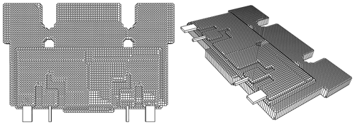
We will take a closer look at a 5 mΩ foil shunt with a resistive foil made of CuMn7Sn, Zeranin 30® (Isabellenhütte2014). The chemical composition of this resistive material in mass percentages is as follows: Mn 7 %, Sn 2.3 %, Cu (rest). The specific conductivity is: σ=3.448Ω-1 mm−2 m. The temperature coefficient in the temperature range of 20 to 60 C is max. ±3 ppm K−1. This resistive foil is glued to a 0.5 mm thick carrier plate and the carrier plate to a 2 mm thick mounting body, both made of aluminum; see Fig. 1. The thickness of the glue layers amounts to a few microns, but this additional distance is negligible compared to the thickness of carrier plate and mounting body.

https://www.j-sens-sens-syst.net/8/329/2019/jsss-8-329-2019-f01

Figure 1Fast Henry (Kamon et al.1996) 3-D simulation model of a typical 5 mΩ foil shunt with resistance foil, carrier plate and mounting body.

The numerical field simulation program Fast Henry (Kamon et al.1996) from the Fast-Field-Solvers bundle calculates the frequency-dependent self-inductance, mutual inductance, resistance, reactance and the current distribution of complex conductor geometries. The simulation scripts are available in Schönecker-Baußmann (2019) and take into account the current displacement due to proximity effect, skin effect and other eddy currents. Fast Henry is a field solver that is able to solve Maxwell's equations for the magnetic field in the quasi-static domain. Saturation is not considered in this simulation, because ferromagnetic materials are not supported. The simulation assumes the system has settled at each frequency and has reached a steady state. The frequency response of the shunt for distorted waveforms can be extrapolated by considering each frequency component separately and adding the partial results in a linear and time-invariant system. The graphical representation is created using Gnu Octave (Eaton et al.2011).

3 Current distribution and eddy currents

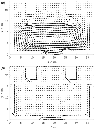
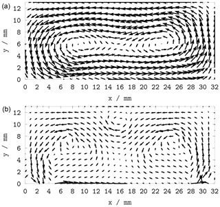
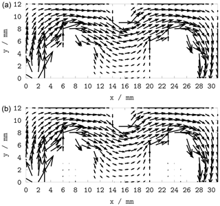
For qualitative consideration, the simulation of the current distribution in Figs. 24 is done at 10 Hz and 100 kHz. The signal frequency 10 Hz represents the low-frequency behavior and 100 kHz is considered as the useful maximum bandwidth of this foil shunt.

https://www.j-sens-sens-syst.net/8/329/2019/jsss-8-329-2019-f02

Figure 2Eddy currents in the mounting body at the signal frequency 10 Hz (a) and 100 kHz (b).

Download

https://www.j-sens-sens-syst.net/8/329/2019/jsss-8-329-2019-f03

Figure 3Eddy currents in the carrier plate at the signal frequency 10 Hz (a) and 100 kHz (b).

Download

https://www.j-sens-sens-syst.net/8/329/2019/jsss-8-329-2019-f04

Figure 4Current distribution in the resistive element at the signal frequency 10 Hz (a) and 100 kHz (b).

Download

No significant difference in the current distribution of the signal current in the resistive element was detected between the signal frequency of 10 Hz and 100 kHz; see Fig. 4. Figures 2 and 3 show that in the carrier plate as well as in the mounting body the induced eddy currents are strongly frequency dependent.

4 Effective resistance and reactance of the shunt versus the signal frequency

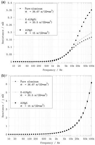
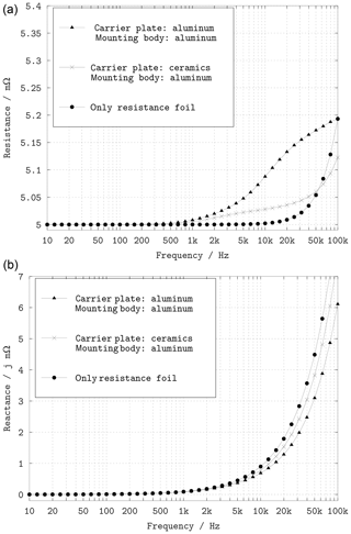
The effective resistance R and the electrical reactance X is analyzed over the frequency from lower frequencies to up to 100 kHz for the quantitative representation in the impedance plots in Figs. 57.

https://www.j-sens-sens-syst.net/8/329/2019/jsss-8-329-2019-f05

Figure 5Simulation of the shunt resistance (the real part in a) and the shunt reactance (the imaginary part in b) with different conductance values of the aluminum mounting body and carrier plate.

Download

https://www.j-sens-sens-syst.net/8/329/2019/jsss-8-329-2019-f06

Figure 6Simulation of the shunt resistance (the real part in a) and the shunt reactance (the imaginary part in b) with variation in the assembly of the shunt: carrier plate made of aluminum or ceramics and the resistive foil itself without carrier plate and mounting body.

Download

Two main parameters were varied and the behavior of the foil shunt examined:

  1. the electrical conductivity of the carrier plate and mounting body made of () pure aluminum, (×) E-AlMgSi and () an aluminum material with a relative low conductivity AlMg5 (the conductivity values of different aluminum alloys are taken from GDA1999, chap. 2.2.1, Table 5);

  2. the structure of the foil shunt: () complete stackup with a carrier plate and the mounting body made of E-AlMgSi and alternatively (×) the carrier plate made of non-conductive ceramics and () the resistive foil itself without carrier plate and mounting body used for comparison.

Figure 5 shows in a very visual way that with a lower conductivity of different aluminum alloys the eddy current losses and thus the effective shunt resistance increase. The inductance of this setup corresponds to approximately 14.3 nH at low frequency, decreasing to 9.7 nH at 100 kHz, and is almost independent of the aluminum conductivity.

The dependency of the high-frequency shunt resistance in Fig. 6 on shunt structure shows a significant improvement through the exchange of the carrier plate with a non-conductive ceramic version. Eddy currents are also induced in the mounting body with its slightly higher distance to the resistive foil, so removing this mounting body in the simulation leads to a nearly perfect frequency response of the resistance up to 10 kHz. Self-evidently the voltage drop at the shunt increases due to its inductance, but different from the increasing real part of the resistor, the imaginary part of the shunt impedance can be compensated for through a variety of circuitry measures without adverse effects. By way of example an analog resistor–capacitor (RC) low pass filter or a correspondent digital filter can be used to compensate the parasitic inductance of the shunt. Even an arrangement of several resistors in coaxial structure reduces the inductance and improves the frequency response, as originally demonstrated for precision wideband shunts in Budovsky (2009) and previous reports from Budovsky and furthermore enhanced by Bosco et al. (2011), Bergsten and Rydler (2019), and Lind et al. (2008). However, even without a conductive mounting plate the shunt resistance rises at higher frequencies.

https://www.j-sens-sens-syst.net/8/329/2019/jsss-8-329-2019-f07

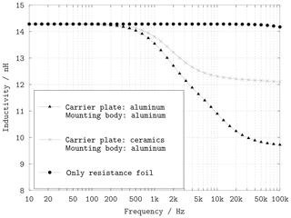
Figure 7Simulation of the shunt inductance with variation in the assembly of the shunt: carrier plate made of aluminum or ceramics and the resistive foil itself.

Download

The slightly lower inductance at higher frequencies of the complete shunt, including the carrier plate and the mounting body made of aluminum in Fig. 6, seems to be favorable compared with the single resistive foil. Figure 7, however, shows the frequency dependence of the inductance. Whereas lower shunt inductance is preferable in general, a nearly constant inductance over frequency is advantageous for effective compensation measures. Here, as well, the closer conductive material is to the resistive foil, the worse the AC characteristics are.

5 Conclusions

Essentially, a “perfect” shunt for DC applications and a shunt optimized for AC applications are to a certain degree mutually exclusive. High-precision foil shunts with a high stability, a good temperature coefficient and low self heating are a good choice for special calibration purposes with an additional compensation of the frequency response. Due to the suboptimal AC behavior, the use of low-ohmic high-precision foil shunts is restricted to measuring instruments with a limited bandwidth. At the expense of shunt production cost and complexity the AC characteristics of foil shunts could be improved by the use of non-conductive carrier materials.

Code availability

The simulation scripts, models and all necessary tools for reproducing the simulations are available at https://doi.org/10.5281/zenodo.3369544 (Schönecker-Baußmann2019). All simulations were run using free software: Fast Henry (https://github.com/ediloren/FastHenry2/tree/WRCad; Kamon et al.1996), Gnu Octave (http://www.gnu.org/software/octave/octave.pdf; Eaton et al.2011) and shell scripts for Linux.

Competing interests

The author declares that there is no conflict of interest.

Acknowledgements

The author would like to thank all colleagues at ZES ZIMMER Electronic Systems GmbH, with special thanks to Bernd Neuner, Matthias Schmidt from PTB, the National Metrology Institute of Germany and Meinhard Schilling from the Technische Universität Braunschweig for the excellent cooperation.

Review statement

This paper was edited by Ravibabu Mulaveesala and reviewed by two anonymous referees.

References

Bergsten, T. and Rydler, K.-E.: Realization of Absolute Phase and AC Resistance of Current Shunts by Ratio Measurements, IEEE T. Instrument. Meas., 68, 2041–2046, https://doi.org/10.1109/TIM.2018.2882927, 2019. a

Bosco, G. C., Garcocz, M., Lind, K., Pogliano, U., Rietveld, G., Tarasso, V., Voljč, B., and Zachovalová, V. N.: Phase Comparison of High Current Shunts up to 100 kHz, IEEE T. Instrument. Meas., 60, 2359–2365, https://doi.org/10.1109/TIM.2011.2108553, 2011. a

Budovsky, I.: Standard of Electrical Power at Frequencies Up to 200 kHz, IEEE T. Instrument. Meas., 58, 1010–1016, https://doi.org/10.1109/TIM.2008.2012376, 2009. a

Eaton, J. W., Bateman, D., Hauberg, S., and Wehbring, R.: GNU Octave, 3rd Edn., available at: http://www.gnu.org/software/octave/octave.pdf (last access: 17 December 2019), 2011. a, b

GDA: Aluminium in der Elektrotechnik und Elektronik, technisches Merkblatt E01, GDA Gesamtverband der Aluminiumindustrie, Düsseldorf, available at: http://www.aluinfo.de/files/_media/dokumente/Downloads/Technische Daten/Merkblaetter/E1_Aluminium_in_der_Elektrotechnik_und_Elektronik.pdf (last access: 17 December 2019), 1999. a

Isabellenhütte: Zeranin 30, Isabellenhütte Heusler GmbH & Co. KG, Dillenburg, available at: https://www.isabellenhuette.de/fileadmin/Daten/Praezisionslegierungen/Datenblaetter_Widerstand/ZERANIN_30.pdf (last access: 17 December 2019), 2014.  a

Kamon, M., Silveira, L., Smithhisler, C., and White, J.: Fast Henry User's Guide, Research Laboratory of Electronics, Department of Electrical Engineering and Computer Science, Massachusetts Institute of Technology, Cambridge, MA, USA, available at: https://github.com/ediloren/FastHenry2/tree/WRCad (last access: 17 December 2019), 1996. a, b, c, d

Lind, K., Sørsdal, T., and Slinde, H.: Design, Modeling, and Verification of High-Performance AC-DC Current Shunts From Inexpensive Components, IEEE T. Instrument. Meas., 57, 176–181, https://doi.org/10.1109/TIM.2007.908602, 2008. a

Schönecker-Baußmann, M.: Supplementary dataset for Journal Article “AC Characteristics of Low Ohmic Foil Shunts Influenced by Eddy Currents in the Mounting Body”, ZES ZIMMER Electronic Systems GmbH, Germany, https://doi.org/10.5281/zenodo.3369544, 2019. a, b

Szwarc, J.: Predicting Drift in Foil Resistors, Vishay Precision Group, Vishay Foil Resistors, available at: http://www.vishaypg.com/docs/63171/TN104.pdf (last access: 17 December 2019), 2012. a

Zandman, F. and Szwarc, J.: Non-Linearity of Resistance/Temperature Characteristic: Its Influence on Performance of Precision Resistors, Vishay Precision Group, Vishay Foil Resistors, available at: http://www.vishaypg.com/docs/60108/VFR_TN108.pdf (last access: 17 December 2019), 2013. a

Download
Short summary
We came across some problems with the current measurement shunts while building a transfer normal power analyzer for 150 kHz within a cooperation project of the manufacturer ZES ZIMMER along with PTB, the National Metrology Institute of Germany and Bundesnetzagentur Berlin. We decided to utilize simulations with the numerical field simulation program Fast Henry to determine the cause of this frequency behavior. We found adequate justification and give recommendations for the shunt manufacturing.