the Creative Commons Attribution 4.0 License.
the Creative Commons Attribution 4.0 License.
 | 14 Jan 2019
Phase optimization of thermally actuated piezoresistive resonant MEMS cantilever sensors
Andi Setiono
Michael Fahrbach
Jiushuai Xu
Maik Bertke
Wilson Ombati Nyang'au
Gerry Hamdana
Hutomo Suryo Wasisto
Erwin Peiner
The asymmetric resonance response in thermally actuated piezoresistive cantilever sensors causes a need for optimization, taking parasitic actuation–sensing effects into account. In this work, two compensation methods based on Wheatstone bridge (WB) input voltage (VWB_in) adjustment and reference circuit involvement were developed and investigated to diminish those unwanted coupling influences. In the first approach, VWB_in was increased, resulting in a higher current flowing through the WB piezoresistors as well as a temperature gradient reduction between the thermal actuator (heating resistor: HR) and the WB, which can consequently minimize the parasitic coupling. Nevertheless, increasing VWB_in (e.g., from 1 to 3.3 V) may also yield an unwanted increase in power consumption by more than 10 times. Therefore, a second compensation method was considered: i.e., a reference electronic circuit is integrated with the cantilever sensor. Here, an electronic reference circuit was developed, which mimics the frequency behavior of the parasitic coupling. By subtracting the output of this circuit from the output of the cantilever, the resonance response can thus be improved. Both simulated and measured data show optimized amplitude and phase characteristics around resonant frequencies of 190.17 and 202.32 kHz, respectively. With this phase optimization in place, a phase-locked-loop (PLL) based system can be used to track the resonant frequency in real time, even under changing conditions of temperature (T) and relative humidity (RH), respectively. Finally, it is expected to enhance the sensitivity of such piezoresistive electro-thermal cantilever sensors under loading with any target analytes (e.g., particulate matter, gas, and humidity).
- Article
(4884 KB) - Full-text XML
- BibTeX
- EndNote


Environmental conditions have a major impact on human well-being, comfort, and productivity. High air pollution levels for example may cause adverse health effects (Al horr et al., 2016; Moreno-Rangel et al., 2018). Therefore, research and development of chemical sensors have been progressively advanced, especially with the technological enhancement in micro-electro-mechanical systems (MEMS), which has led to the realization of highly sensitive and selective microscale sensors (Corigliano et al., 2014). Additionally, MEMS resonators have become favorable devices for measuring concentrations of the undesired chemical substances ubiquitously (e.g., airborne nanoparticles, toxic gases, and humidity) by monitoring their responses in resonant frequency f0 (Bausells, 2015; Li and Lee, 2012; Mathew and Ravi Sankar, 2018; Wasisto et al., 2016, 2015; Xu et al., 2018). Most of these MEMS resonators are often actuated by electrostatic (Zhao et al., 2017), piezoelectric (Hees et al., 2013), or electrothermal (Chu et al., 2018) methods, in which the sensing mechanisms are based on capacitive (Pérez Sanjurjo et al., 2017), piezoelectric (Sviličić et al., 2014), or piezoresistive (Bertke et al., 2016) transductions. Nevertheless, unfavorable direct parasitic coupling due to resistive, capacitive, and thermal effects between the actuating and sensing components of MEMS resonators has been reported (Wasisto et al., 2015; Xu et al., 2018; Chu et al., 2018; Zuo et al., 2010; Bertke et al., 2017a). The parasitic coupling effect of an in-plane thermally actuated silicon-based microcantilever is shown in Fig. 1a, in which the heating resistor (HR, actuating part) induces a direct thermal parasitic coupling to the Wheatstone bridge (WB, sensing part). Subsequently, the thermal parasitic coupling affects the output signal: amplitude (asymmetric) and phase (reversed), as shown in Fig. 1b. The expected amplitude and phase responses should be symmetric and monotonic, respectively, as demonstrated by the same piezoresistive cantilever resonator with an external piezoactuator (Fig. 1c). The piezoelectric shear actuator resulted in an in-plane base point excitation of the cantilever with a very low direct coupling to the WB (i.e., a low parasitic effect). Hence, the optimize signal responses were obtained in this case (Fig. 1d).
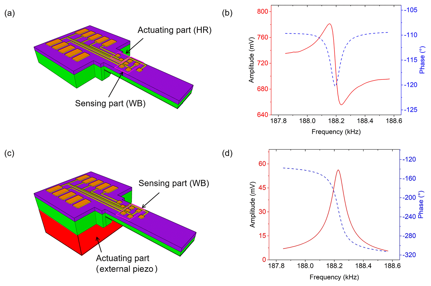
Figure 1(a) Schematic of a thermally actuated cantilever sensor yielding (b) an asymmetric amplitude (red, full) and reversed phase response (blue, dashed). (c) Schematic of the same cantilever sensor actuated by an external piezoelectric shear actuator (HR disabled) yielding (d) a symmetric amplitude (red, full) and monotonic phase response (blue, dashed).
Mathematical approaches shown by Chu et al. (2018) indicate that de-embedding and post data processing have succeeded in revealing a symmetric amplitude shape from the measured asymmetric response of a MEMS resonator. The de-embedding method implements a mathematical model of parasitic parameters and then removes the parasitic characteristics from the overall measurement. Another mathematical model appropriate for de-embedding involves the use of the Fano resonance approach (Bertke et al., 2017a), in which the quality factor (Q) and resonant frequency (f0) are obtained by fitting the measured asymmetric resonance curve using mathematical models shown in Eqs. (1) and (2):
where f0, Q, A, q, g, H, and A0 are center frequency, quality factor, amplitude, asymmetry factor, line width, and gain parameters, respectively. Furthermore, an offset proportional to frequency f is considered with a constant c.
The proposed approaches are however still not feasible in fast tracking and real-time frequency measurement. Phase-locked-loop (PLL)-based systems have broadly been used to realize continuous online resonance tracking of resonant sensors (Wasisto et al., 2014, 2015; Toledo et al., 2016). A PLL can be used to derive characteristic frequencies of a system by tracking a given phase difference between the input and output signals of the system. In the case of cantilever sensors, the resonance phase difference ideally is independent of the resonant frequency. Therefore, the resonant frequency can be monitored by tracking the resonance phase. When the measured phase reaches the desired phase difference, the output frequency of the PLL is interpreted as the resonance frequency. Here, the resonance phase becomes an essential parameter to lock the resonant frequency using PLL-based systems. Nevertheless, PLL systems do not function properly in thermally actuated cantilever sensors due to their reversed phase response. Resonance tracking cannot work in a reversed phase response because there is an ambiguity in the phase response, which subsequently leads to instability during the locking process of resonant frequency. Therefore, there is a need to develop a technique that can guarantee an utmost suppression of parasitic effects on the thermally actuated cantilever sensors. The developed technique is then expected to be able to obtain a symmetrical amplitude shape and optimize the phase characteristic without ambiguity in the phase response (monotonically decreasing). In this work, two methods of mitigating the asymmetric behavior in thermally actuated piezoresistive cantilever sensors are proposed (i.e., Wheatstone bridge (WB) input voltage (VWB_in) adjustment and application (subtraction) of an external reference signal). These techniques are subsequently intended to expedite the locking procedure of resonant frequency based on the PLL mechanism.
A thermally actuated piezoresistive silicon cantilever resonator (Fig. 2a) comprises two main parts (i.e., for mechanical actuation and electrical sensing, respectively), in which both are realized as diffused p-type silicon resistors (Fig. 2b). Mechanical (thermal) actuation is obtained by applying an AC voltage Vaccos(ωt) superimposed to a DC voltage Vdc on a heating resistor (HR), which is located at the clamped end of the cantilever. The resulting power loss (dissipation) P can be described as
where R is the resistance of HR, Vdc and Vac are the DC and AC voltage amplitudes, respectively, and ω is the excitation frequency. This term will lead to the Joule heating effect (Wasisto et al., 2015; Brand et al., 2015) yielding a lateral temperature gradient around the HR, as shown in Fig. 2c.

Figure 2(a) Optical micrograph of the cantilever sensor which has a beam length of ∼1000 µm, (b) showing the HR and the U-shape WB at the clamp end with the dimensions of the resistors R1 to R4 of 60×10 µm2. Furthermore, (c) shows the temperature distribution around HR obtained by FEM (COMSOL Multiphysics 4.4b). In (d) the electrical circuit diagram with the exciting and sensing parts is displayed (V+ is connected to R1 and R3 represents the supply voltage of the WB).
After a strain gradient has been induced, it will finally result in a cantilever bending in the lateral direction (in-plane mode). The DC component is necessary to have a large excitation amplitude at the excitation frequency ω (third term in Eq. 3). The response to this mechanical actuation is sensed by four piezoresistors configured in a U-shape WB, where this design has been adapted to the strain distribution at the cantilever top surface during lateral bending. Lastly, the electrical signal generated by the WB is amplified using an external instrumentation amplifier (Texas Instruments, INA217), as depicted in Fig. 2d.
As shown in finite element modeling (FEM, COMSOL Multiphysics 4.4b, cf. Fig. 2c), the sensing piezoresistors near the heating resistor (i.e., R1 and R2) are exposed to more thermal heating than R3 and R4. This parasitic thermal coupling, which is expected to result in an asymmetric response around resonance, can be described by
where T and λ are the temperature and a coupling factor, respectively. When using voltage supply, thermal coupling to the WB contributes to the output voltage of the WB (VWB_out) according to
where VWB_in is the supply voltage of the WB, R=Ri (i=1, …, 4) is the resistance of the WB, π is the (effective) piezoresistive coefficient of the p-type silicon WB, and σ is the average stress acting on the cantilever surface at the position of the WB. Ideally, the WB output voltage (VWB_out) should be linearly proportional only to the stress σ acting on the Wheatstone bridge, which is caused by the cantilever deflection. However, the temperature dependences of π and σ can cause additional parasitic effects on VWB_out according to
where π0 and σ0 represent the piezoresistive coefficient and the average stress, respectively, at zero temperature increase, i.e., the average temperature increase induced by HR at WB . The temperature coefficients of piezoresistivity and thermal expansion are given by β and γ, respectively. Substituting Eqs. (6) and (7) in Eq. (5) results in
Based on Eq. (8), we can expect a nonlinear dependence of the WB output voltage on the temperature increase (ΔT). Furthermore, temperature distribution across the WB is not uniform, but is biased towards the HR; i.e., resistors R1 and R2 are expected to be exposed to a higher ΔT than R3 and R4. Increasing VWB_in reduces ΔT, while its absolute nonuniformity is only slightly lower, as will be shown below.
In principle, removing asymmetry from the resonance response of a MEMS-based resonator can be carried out by cancellation or minimization of the parasitic effects at the resonator output. In the first approach, the WB input voltage (VWB_in) was gradually increased (from 1 to 3.3 V), thereby inducing an increasing heating effect on the WB. Consequently, the temperature gradient towards HR should reduce and finally eliminate the thermal parasitic coupling effect. We used FEM (COMSOL Multiphysics 4.4b; cf. Fig. 3) to show the temperature increase at the WB induced by increasing VWB_in from 1 to 3.3 V. As shown in this simulation, the voltages applied to HR (VHR=5 V) and VWB_in generate the temperatures T1 and T2, respectively. The resultant average temperature difference due to VWB_in=3.3 V amounts to 1.25 K, which is lower compared to the 2.23 K obtained for VWB_in=1 V. Again, T2 is not uniformly distributed at VWB_in=3.3 V, as indicated by the deviation of ΔT across the WB of ±0.480 K vs. ±0.493 K at VWB_in=1 V. According to Eq. (8) and the reduced ΔT, a smaller parasitic temperature coupling to the WB may be expected at VWB_in=3.3 V, which was confirmed by the measurements shown in Fig. 4, yielding a symmetric amplitude shape and a monotonic phase response. Accordingly, the phase difference shows a nearly ideal shape with a 90∘ transition occurring at the frequency corresponding to the amplitude maximum.
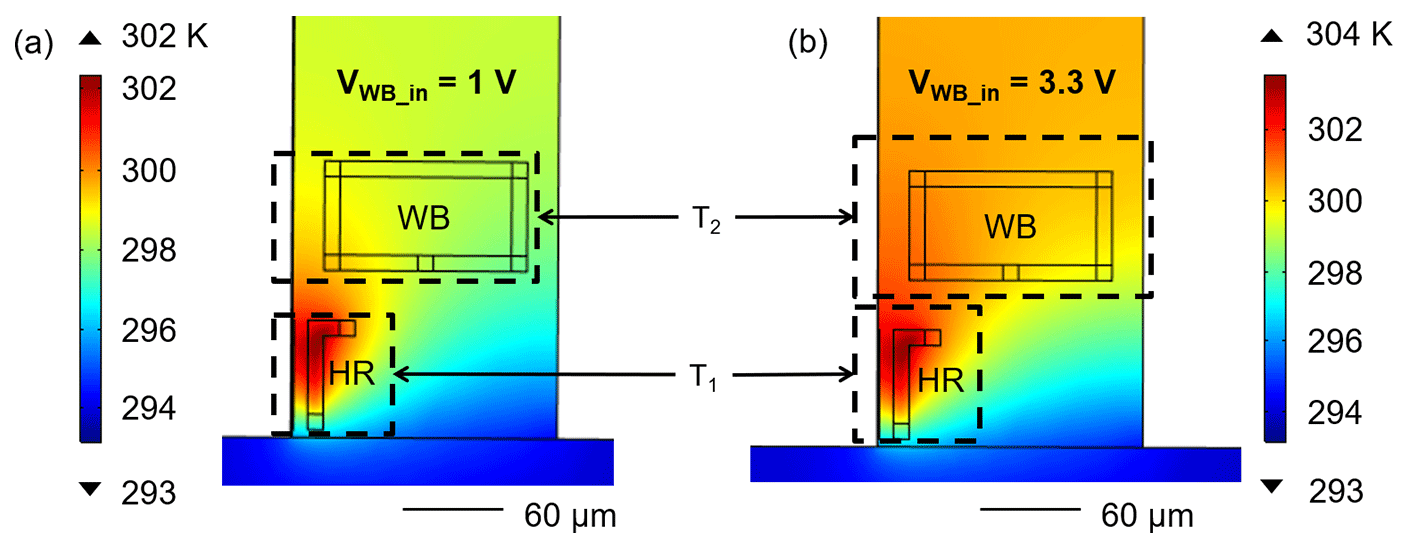
Figure 3FEM for a thermally actuated cantilever sensor with (a) VWB_in=1 V and (b) VWB_in=3.3 V. The average temperature increase at the WB amounts to K and 1.25±0.480 K in (a) and (b), respectively.
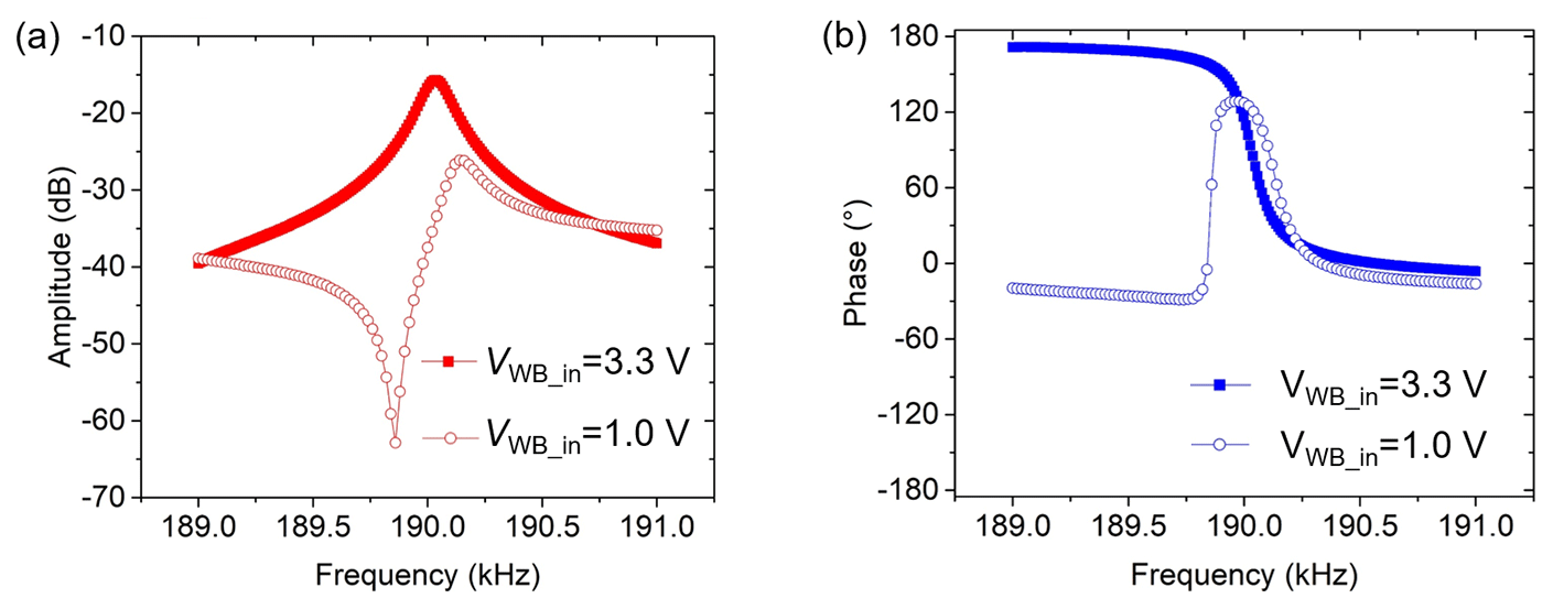
Figure 4Measured (a) amplitude (red) and (b) phase characteristics (blue) of a thermally actuated cantilever sensor at different WB input voltages: VWB_in=1 V (open line), VWB_in=3.3 V (solid line).
However, compared to that of VWB_in=1 V, the power consumption produced by VWB_in=3.3 V is boosted by an order of magnitude. To relieve the need for such a large increase in VWB_in, an optimized design of the actuating–sensing components is necessary in such a way as to reduce the thermal coupling effect. Stationary FEM simulation delineated in Fig. 5b, c, and d shows that shifting HR away from WB yields a lower thermal distribution compared to the current design (Fig. 5a) at otherwise equal operating conditions (i.e., VHR=5 V and VWB_in=1 V). Nevertheless, lower thermal distribution is followed by less total displacement (Dt) of the cantilever beam. In this simulation, total displacement changes from 17.79 to 15.95, 13.04, and 10.18 nm, respectively, resulted for distances of HR to WB of 33, 43, 58, and 73 µm. Correspondingly, redesigned cantilever structures will be fabricated and investigated in the near future. Therefore, as an alternative we proposed a second method that involves the subtraction of a reference from the sensor output signal.
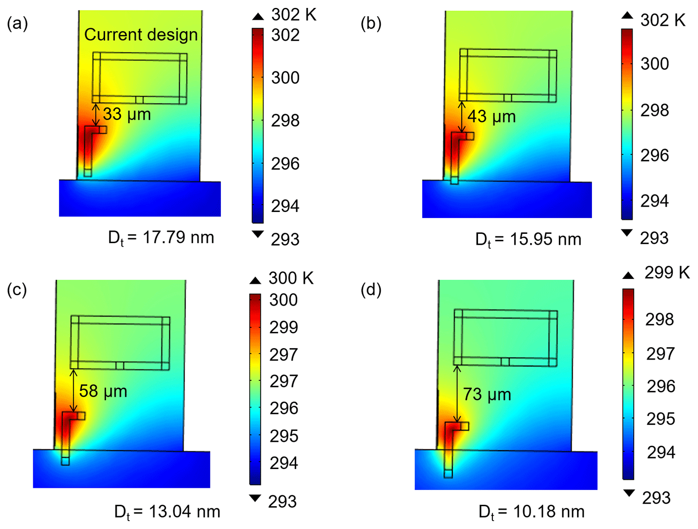
Figure 5FEM for a thermally actuated cantilever sensor based on the current design (a) and with HR shifted away (b, c, d) from the WB towards the cantilever frame.
A reversed phase response often occurs simultaneously with an asymmetric amplitude shape, i.e., a Fano resonance. According to Bertke et al. (2017a), a Fano resonance is yielded by mixing a discrete state (Lorentzian line shape) with a constant continuum background. Therefore, in order to obtain a symmetrical amplitude shape (Lorentzian line shape), elimination of the continuum background should be done by subtracting a corresponding characteristic. Simultaneously, the symmetrical amplitude shape should then be accompanied by a monotonic phase response.
In this study, amplitude and phase responses of a reference signal were subtracted from the outputs of the thermally actuated microcantilever as shown in Fig. 6. The reference signal was created by an RCL (resistor, capacitor, and inductor) high-pass filter (HPF) with a cut-off frequency of ∼50 kHz. In this case, the RCL-HPF yields a small slope of both amplitude and phase responses corresponding to the frequency dependence of the baseline of the cantilever signal around the working frequency (i.e., ∼202 kHz). Hence, the RCL-HPF circuit was intended to generate and provide a suitable characteristic reference signal, which could then be subtracted from the cantilever signal. The variable resistors VR1 and VR2 were tuned to control the level of reference amplitude and phase responses, respectively. Furthermore, subtraction was performed using both negative and positive voltage input terminals of a lock-in amplifier (MFLI, Zurich Instruments). The positive (V+) and negative (V−) inputs of the lock-in amplifier were connected to the output signals of the cantilever and reference, respectively, and the resultant amplifier output voltage (VO) was then determined internally in the MFLI lock-in amplifier.

Figure 6Setup of phase characteristic optimization by reference-signal subtraction consisting of a voltage divider and an RCL-HPF circuit.
In order to yield a symmetric line shape at the differential output, the amplitude and phase of the reference signal should be placed close to the out-of-resonance baselines of amplitude and phase of the thermally actuated microcantilever. Subtracting the reference signal from an asymmetric amplitude shape was simulated using LTspice, as depicted in Fig. 7. From the simulation, it was found that the asymmetric amplitude response (Fig. 7a, open-red line) and the reversed phase response (Fig. 7b, open-blue line) of a circuit can be eliminated using a reference signal set close to the asymmetric baseline. These configurations result in a resonant signal with a symmetric amplitude shape about f0 and the phase difference is 90∘ as shown in Fig. 7c.
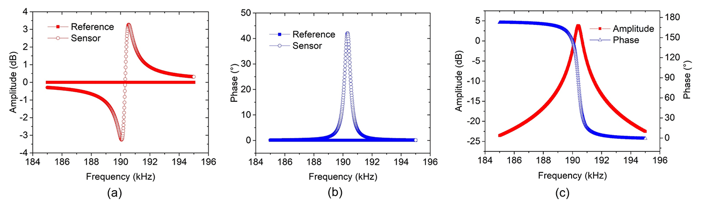
Figure 7Differential simulation of (a) an asymmetric amplitude shape and (b) a reversed phase response with a reference signal, (c) resulting in a compensated symmetric amplitude shape (red, full squares) and a monotonic phase (blue, open triangles) response about f0.
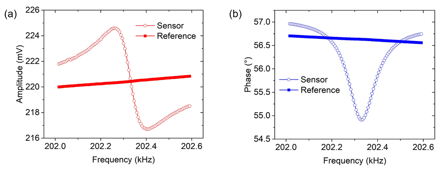
Figure 8Measured sensor and reference signals: (a) amplitude response of asymmetric shape with a nearly constant reference, and (b) a reversed phase response with reference.
A mathematical model of polar and Cartesian equations was used to analyze the amplitude (A) and phase (φ) of a differential output [A,φ]. Polar equations noted by Eq. (9) represent the amplitude and phase responses of the sensor output (index “S”) and the reference signal (index “R”). The polar form is then converted to the Cartesian form to obtain both sensor [x1,y1] and reference [x2,y2] signals, as expressed in Eqs. (10) and (11), respectively. Then, x and y components of a reference signal are subtracted from the sensor signal (Eq. 12). Finally, the amplitude of the differential output can be calculated by Eq. (13), while the phase response is calculated using Eq. (14):
Experimental results depicted in Fig. 8 show that the sensor amplitude (open red line) has a baseline between ∼221.79 and ∼218.50 mV, whilst the phase baseline (open blue line) ranges from ∼56.96 to ∼56.75∘ in the frequency range of 202.0 to 202.6 kHz. The reference signal was then set closer to the baseline of the sensor signal by adjusting VR1 and VR2 (shown in Fig. 6). In the same frequency domain, the measured reference amplitude (solid red line) was observed to increase from ∼219.99 to ∼220.84 mV, whereas the phase response (solid blue line) decreases from ∼56.70 to ∼56.56∘. The observed changes in the amplitude (increment) and phase (decrement) of the reference signals are characteristic of an electronic filter, which, in the case of RCL-HPF, covers an extended phase range of and .
Subtracting the reference from the sensor signal demonstrates a symmetric amplitude shape (Fig. 9a, solid red squares) and a monotonic phase response (solid blue squares, Fig. 9b) in the range of ∼94.48 to . These experimental results are confirmed by calculation approaches, i.e., implementation of Eqs. (13) and (14) for the amplitude (black solid line, Fig. 9a) and phase (purple solid line, Fig. 9b), respectively. As a result, both experimental and calculated results generate symmetrical amplitude and monotonic phase with small deviations. The next step will be to generate a suitable reference signal by a programmed software to enable automatic reference adjustment.
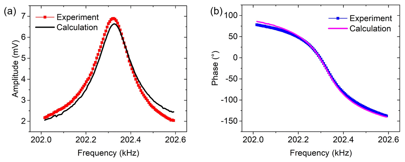
Figure 9Measured and calculated graphs for (a) amplitude and (b) phase response of differential output signals.
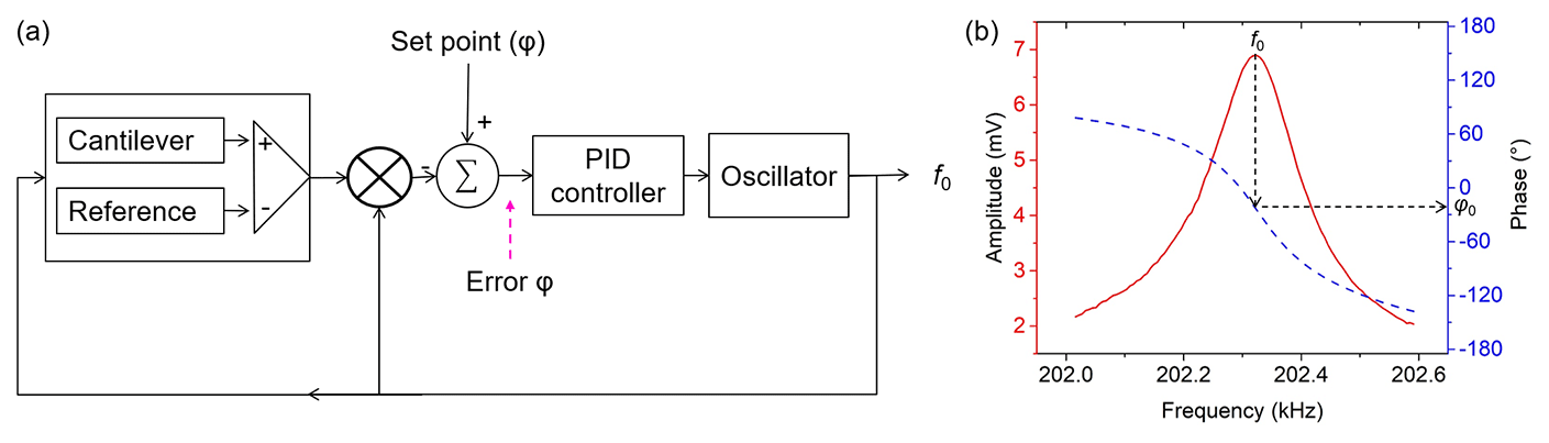
Figure 10(a) Phase-locked-loop setup for resonance tracking by employing (b) symmetric amplitude shape with monotonic phase response.
Tracking of the resonance frequency is performed by implementing the PLL technique, as shown in Fig. 10a. Reference subtraction from the cantilever output results in a symmetric amplitude shape (red solid line) and a monotonic phase response with no ambiguity (blue dashed line), as depicted in Fig. 10b. The monotonic phase is applicable in the PLL-based system for resonant frequency tracking. From the highest peak of amplitude, the resonance phase φ0 is determined. It is subsequently used as a set point of phase. The set point value is subtracted from the measured phase difference, generating an error signal. This error signal is then used by the PID (proportional, integral, derivative) controller to calculate a new output frequency, which is expected to result in a smaller error signal. When the error signal reaches zero, the resonance frequency f0 is found and will be tracked henceforth. Setting of the parameters Kp (proportional gain), Ki (integral gain), and Kd (derivative gain) determines how quickly and how precisely the controller can lock the resonant frequency. The Kp and Ki will have the effect of reducing the rise time and eliminating the steady-state error, respectively, while Kd is effective for decreasing the overshoot. However, too-high values of Kp, Ki, and Kd will result in an unstable response; conversely, too-low values will lead to sluggish steering. Therefore, optimization is needed for these parameters to get the best tracking control, i.e., as fast and precise as possible.
Two experimental setups shown in Figs. 11 and 12 were used to confirm the performance of the monotonic phase response that is obtained by subtracting the reference signal from the sensor output (i.e., the second method). In the first case, a bare silicon cantilever is used, while in the second case the cantilever was functionalized with a bilayer of ZnO and chitosan. Tracking of the resonant frequency was realized by using a lock-in amplifier with an integrated PLL system (MFLI, Zurich Instruments). For comparison, a commercial instrument to measure relative humidity (RH) and temperature (T) (Chauvin Arnoux, CA 1246 Thermo-hygrometer) was used simultaneously. By these two experiments, we investigated whether the resultant monotonic phase response will yield an improved response during the resonance frequency tracking.
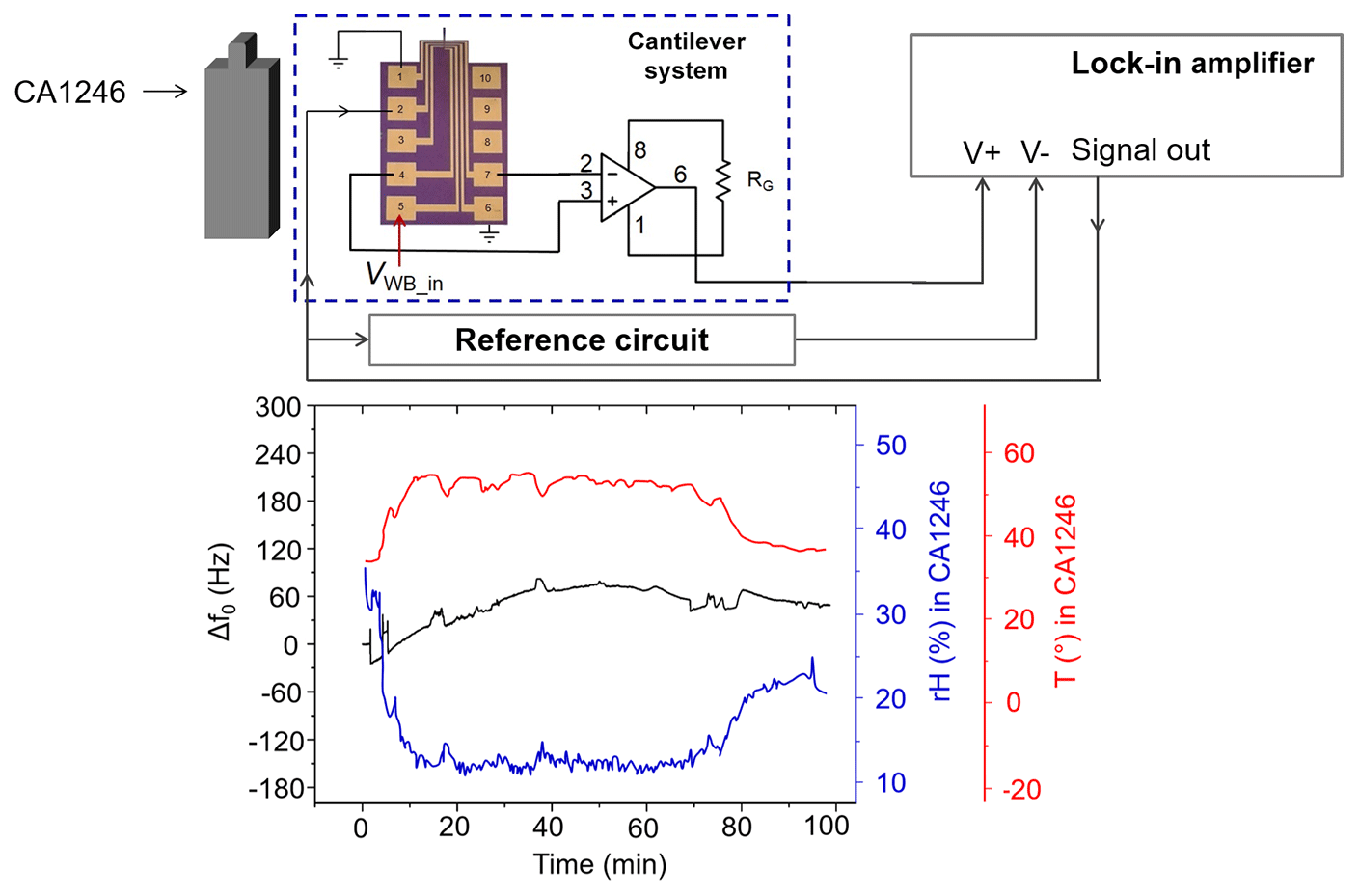
Figure 11Resonant frequency shift (Δf0) of a piezoresistive silicon cantilever under exposure of outdoor temperature (T) and relative humidity (RH).
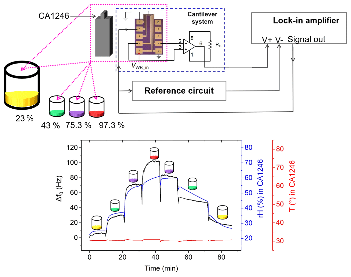
Figure 12Resonant frequency shift (Δf0) of a piezoresistive silicon cantilever with a ZnO/chitosan sensing layer under a controlled environment of temperature and relative humidity.
From the first test configuration, depicted in Fig. 11, both T and RH are expected to generate a shift in resonant frequency. The temperature coefficient of Young's modulus and the thermal expansion coefficient are the main intrinsic parameters, which cause a change in the spring constant (k). By increasing the temperature, the spring constant k decreases, thereby causing the resonant frequency f0 to decrease. On the other hand, an increase in humidity leads to an enhanced absorption of water molecules on the cantilever, leading to an increase in its mass and a decrease in f0. Thus, the effects of temperature and humidity changes will cancel out each other up to a certain level in resonance. This is evidently shown in Fig. 11, in which the shift in resonance ( Hz) is relatively stable especially after 30 min of tracking. Previously, larger resonant frequency shifts Δf=7.275 kHz and Δf=444 Hz corresponding to added masses of 0.20 µg and 38 ng under cigarette smoke exposure conditions were reported by Bertke et al. (2017a, b). The small shift in resonance (i.e., Hz) realized in this study makes the MEMS sensor more sensitive for the detection of particulate matter.
The second test configuration involved assessment of the resonance response and relative humidity using a cantilever and commercial sensor, respectively, under the same conditions. The cantilever is initially coated with ZnO film and chitosan. Both sensors were put in a bottle filled with chemical solutions under different saturation vapor pressures. These solutions release different humidity levels depending on the type of solution (i.e., potassium acetate: 23 %; potassium carbonate: 43 %; sodium chloride: 75.3 %; and potassium sulfate: 97.3 %). The experimental results (Fig. 12) show a good correlation between cantilever and commercial sensor in the ascending range of RH from 0 % to 60 %. Above this range, we find much worse agreement between cantilever and commercial sensor, which we assign to a slower response of the commercial sensor at large RH. In the case of the cantilever direct exposure and fast reaction of water molecules are possible with the ZnO/chitosan sensing layer, leading to an increase in adsorbed mass and thus a fast responding frequency shift. Correspondingly, on the descending part of the curve, desorption is much faster from the cantilever than indicated by the commercial hygrometer.
Asymmetric resonance in thermally actuated piezoresistive cantilever sensors has been successfully suppressed by adjusting the supply voltage VWB_in of the Wheatstone bridge (WB) and subtracting a reference signal. Both methods reveal monotonic phase responses that are suitable for implementation in a phase-locked-loop (PLL) system for tracking the resonant frequency of the sensor. Adjustment of VWB_in not only directly reduces the parasitic coupling effect, but also leads to increased power consumption. Further works will be necessarily done to optimize the design of the actuating–sensing components (i.e., HR and WB) as well as their operating conditions (i.e., VDC, VAC, and VWB_in). By subtraction of a constant reference, symmetric amplitude shapes can be effectively obtained from measured asymmetric resonance signals. Monotonic phase responses earned by this technique have been employed successfully in a PLL system, resulting in effective frequency tracking under changing temperature (T) and relative humidity (RH). However, further investigation is still necessary to implement reference signals under a wide range of conditions (e.g., in humidity measurement). Moreover, automatic adjustment of reference parameters, design of an on-chip reference, and implementation of a symmetric heat actuator design will become further challenges to be undertaken.

Andi Setiono obtained his Bachelor of Sciences degree in electronics and instrumentation from the Department of Physics, Gadjah Mada University (UGM), Yogyakarta, Indonesia, in 2009. In 2015, he finished his masters study in electronics and photonics from the Department of Electrical Engineering, University of Indonesia. Since 2010, he has been part of the Optoelectronics Research Group at the Research Center for Physics, Indonesia Institute of Sciences (LIPI), working in the field of fiber Bragg grating sensors for landslide monitoring and weight measurement. Since December 2016, he has been a PhD student at the Institute of Semiconductor Technology (IHT), TU Braunschweig, Germany, in the IG-Nano Project (i.e., Indonesian-German Center for Nano and Quantum Technologies) supported by LENA and LIPI. His PhD study is funded by the Ministry of Research, Technology and Higher Education of the Republic of Indonesia (RISTEKDIKTI). His research interests include electronic systems for resonant silicon MEMS/NEMS sensors.

Michael Fahrbach studied electrical engineering at Braunschweig University of Technology and obtained his MSc degree in 2017. Currently, he is working as a PhD student at the Institute of Semiconductor Technology (IHT), TU Braunschweig and Laboratory for Emerging Nanometrology (LENA), Germany. His research is focused on further developing MEMS-based sensors and measurement systems for high-speed contact resonance spectroscopy (CRS) measurements.

Jiushuai Xu studied applied chemistry and biochemistry at Northwest A&F University in Yangling, China, and obtained his MSc degree in 2015. Currently, he is pursuing his PhD degree at the Institute of Semiconductor Technology at TU Braunschweig and Laboratory for Emerging Nanometrology. His research interests are the fabrication of nanostructures and thin films of metal oxides and organic materials, and MEMS/NEMS piezoresistive silicon humidity and gas sensors.

Maik Bertke received a Master of Science degree in electrical engineering from the Technische Universität Braunschweig, Germany, in 2016. Currently, he is working towards a PhD degree at the Institute of Semiconductor Technology (IHT), TU Braunschweig and Laboratory for Emerging Nanometrology, Germany, where his main interests are in the fields of resonant micro-/nano-electromechanical systems (MEMS/NEMS)-based sensors.

Wilson Ombati Nyang'au received BSc and MSc degrees in physics from the Jomo Kenyatta University of Agriculture and Technology, Kenya, in 2008 and 2012, respectively. He has been working at the Department of Metrology in the Kenya Bureau of Standards since 2011. Currently, he is pursuing his PhD degree at the Institute of Semiconductor Technology (IHT), TU Braunschweig, Germany. His research interests include microcantilever-based sensors for liquid-borne particle detection, M/NEMS, and mass metrology.

Gerry Hamdana received his Bachelor of Engineering degree in mechanical engineering from the Esslingen University of Applied Science in 2012 and his Master of Science degree in mechanical engineering, specializing in mechatronic/microsystems technology, from the Braunschweig University of Technology (TU Braunschweig), Germany, in 2015. He finished his PhD work in 2018 at the Institute of Semiconductor Technology (IHT), TU Braunschweig, Germany. His research interests include semiconductor processing, microsystems technology and micro-/nano-electromechanical systems (MEMS/NEMS).

Hutomo Suryo Wasisto received the Doktor-Ingenieur (Dr.-Ing.) degree in Electrical Engineering (summa cum laude) from the Technische Universität Braunschweig, Germany, in 2014. He was a postdoctoral research fellow at the School of Electrical and Computer Engineering (ECE), Georgia Institute of Technology, Atlanta, GA, USA, in 2015–2016. Since 2016, he has been head of the Optoelectromechanical Integrated Nanosystems for Sensing (OptoSense) Group at the Laboratory for Emerging Nanometrology (LENA) and Institute of Semiconductor Technology (IHT), Technische Universität Braunschweig, as well as an initiator and CEO of the Indonesian-German Center for Nano and Quantum Technologies (IG-Nano), Braunschweig, Germany. His main research interests include nano-opto-electro-mechanical systems (NOEMS), nanosensors, nanoelectronics, nanoLEDs, nanogenerators, and nanometrology. He has received several international scientific awards (i.e., the Young Materials Scientist Award at MRS-id 2018, the Transducer Research Foundation (TRF) Travel Grant Award at Transducers 2015, the Walter Kertz Study Award 2014 at TU Braunschweig, the Best Paper Award at IEEE NEMS 2013, and the Best Young Scientist Poster Award at Eurosensors 2012).

Erwin Peiner received diploma and Dr. rer. nat. degrees in physics from the University of Bonn, Germany, in 1985 and 1988, respectively, and the Venia Legendi degree in semiconductor technology from the Technical University (TU) Braunschweig, Braunschweig, Germany, in 2000. In 2002 he did a professor internship at Volkswagen AG Headquarters, Electronics Research Department, Wolfsburg, Germany. Since 2015 he has been an associate professor at TU Braunschweig, where he is the leader of the Semiconductor Sensors and Metrology Group at the Institute of Semiconductor Technology (IHT) and the Laboratory for Emerging Nanometrology (LENA). His current research interests include design, fabrication, assembly, and testing of Micro/Nano Electro Mechanical Systems (M/NEMS) for industrial applications like condition monitoring, tactile surface and force metrology, pollution monitoring, environmental sensing, and energy harvesting. He has published more than 300 papers in international journals and conference proceedings.
Research data are available upon request to the authors.
AS simulated and analyzed the FEM modeling; simulated, assembled, and fabricated the electronic circuit for the subtraction method; designed and performed all the tests and measurements; analyzed measurement data; and drafted the manuscript. MF contributed to realizing the data acquisition; analyzing and interpreting data of the bridge adjustment; and reviewing the principle of the PID controller. JX and MB designed and fabricated the cantilever sensors used for this study, discussed the results and contributed to interpreting the FEM simulation. WON and GH reviewed and discussed the simulation and experimental results and contributed to the manuscript. HSW critically revised the manuscript for important intellectual content. EP supervised the work; reviewed and discussed results; provided recommendations for improving the manuscript; and gave final approval of the version to be submitted and any revised version.
The authors declare that they have no conflict of interest.
This article is part of the special issue “Sensors and Measurement Systems 2018”. It is a result of the “Sensoren und Messsysteme 2018, 19. ITG-/GMA-Fachtagung”, Nürnberg, Germany, from 26 June 2018 to 27 June 2018.
This project has received funding from the EMPIR program co-financed by the
Participating States and from the European Union's Horizon 2020 research and
innovation program under no. 17IND05 MicroProbes. Andi Setiono would like to
thank the Ministry of Research, Technology and Higher Education of the
Republic of Indonesia (RISTEKDIKTI) for the PhD scholarship of RISET-Pro
under no. 343/RISET-Pro/FGS/VIII/2016 (World Bank loan no. 8245-ID) and the
Indonesian-German Center for Nano and Quantum Technologies (IG-Nano) for the
support. Jiushuai Xu, Maik Bertke, and Wilson Ombati Nyang'au are grateful
for funding from the China Scholarship Council (CSC) under grant CSC
no. 201506300019, from “Niedersächsisches Vorab”, Germany, through the
“Quantum- and Nanometrology (QUANOMET)” initiative within the project of
“NP 2-2”, and from the German Federal Ministry for Economic Cooperation and
Development (BMZ) within the Braunschweig International Graduate School of
Metrology, respectively. Hutomo Suryo Wasisto acknowledges the Lower Saxony
Ministry for Science and Culture (N-MWK) for funding of the LENA-OptoSense
group. We are also grateful to Angelika Schmidt, Maike Rühmann,
Aileen Michalski, Karl-Heinz Lachmund, Zhenshuo Ding, Xuejing Li, and
Ratna Indrawijaya for their assistance during preparation of research tools
as well as many fruitful discussions.
Edited
by: Walter Lang
Reviewed by: two anonymous referees
Al horr, Y., Arif, M., Katafygiotou, M., Mazroei, A., Kaushik, A., and Elsarrag, E.: Impact of indoor environmental quality on occupant well-being and comfort: A review of the literature, International Journal of Sustainable Built Environment, 5, 1–11, https://doi.org/10.1016/j.ijsbe.2016.03.006, 2016.
Bausells, J.: Piezoresistive cantilevers for nanomechanical sensing, Microelectron. Eng., 145, 9–20, https://doi.org/10.1016/j.mee.2015.02.010, 2015.
Bertke, M., Hamdana, G., Wu, W., Marks, M., Wasisto, H. S., and Peiner, E.: Asymmetric resonance frequency analysis of in-plane electrothermal silicon cantilevers for nanoparticle sensors, J. Phys.-Conf. Ser., 757, 12006, https://doi.org/10.1088/1742-6596/757/1/012006, 2016.
Bertke, M., Hamdana, G., Wu, W., Wasisto, H. S., Uhde, E., and Peiner, E.: Analysis of asymmetric resonance response of thermally excited silicon micro-cantilevers for mass-sensitive nanoparticle detection, J. Micromech. Microeng., 27, 64001, https://doi.org/10.1088/1361-6439/aa6b0d, 2017a.
Bertke, M., Wu, W., Wasisto, H. S., Uhde, E., and Peiner, E.: Size-selective electrostatic sampling and removal of nanoparticles on silicon cantilever sensors for air-quality monitoring, in: 2017 19th International Conference on Solid-State Sensors, Actuators and Microsystems (TRANSDUCERS), 2017 19th International Conference on Solid-State Sensors, Actuators and Microsystems (TRANSDUCERS), Kaohsiung, Taiwan, IEEE, 1493–1496, 2017b.
Brand, O., Dufour, I., Heinrich, S. M., and Josse, F.: Resonant MEMS: Fundamentals, Implementation and Application, edited by: Brand, O., Dufour, I., Heinrich, S. M., and Josse, F., Advanced Micro & Nanosystems, Wiley-VCH, Weinheim, Germany, 2015.
Chu, C.-C., Dey, S., Liu, T.-Y., Chen, C.-C., and Li, S.-S.: Thermal-Piezoresistive SOI-MEMS Oscillators Based on a Fully Differential Mechanically Coupled Resonator Array for Mass Sensing Applications, J. Microelectromech. Syst., 27, 59–72, https://doi.org/10.1109/JMEMS.2017.2778307, 2018.
Corigliano, A., Ardito, R., Comi, C., Frangi, A., Ghisi, A., and Mariani, S.: Microsystems and Mechanics, Procedia IUTAM, 10, 138–160, https://doi.org/10.1016/j.piutam.2014.01.015, 2014.
Hees, J., Heidrich, N., Pletschen, W., Sah, R. E., Wolfer, M., Williams, O. A., Lebedev, V., Nebel, C. E., and Ambacher, O.: Piezoelectric actuated micro-resonators based on the growth of diamond on aluminum nitride thin films, Nanotechnology, 24, 25601, https://doi.org/10.1088/0957-4484/24/2/025601, 2013.
Li, X. and Lee, D.-W.: Integrated microcantilevers for high-resolution sensing and probing, Meas. Sci. Technol., 23, 22001, https://doi.org/10.1088/0957-0233/23/2/022001, 2012.
Mathew, R. and Ravi Sankar, A.: A Review on Surface Stress-Based Miniaturized Piezoresistive SU-8 Polymeric Cantilever Sensors, Nano-Micro Lett., 10, 25, https://doi.org/10.1007/s40820-018-0189-1, 2018.
Moreno-Rangel, A., Sharpe, T., Musau, F., and McGill, G.: Field evaluation of a low-cost indoor air quality monitor to quantify exposure to pollutants in residential environments, J. Sens. Sens. Syst., 7, 373–388, https://doi.org/10.5194/jsss-7-373-2018, 2018.
Pérez Sanjurjo, J., Prefasi, E., Buffa, C., and Gaggl, R.: A Capacitance-To-Digital Converter for MEMS Sensors for Smart Applications, Sensors (Basel, Switzerland), 17, 1312, https://doi.org/10.3390/s17061312, 2017.
Sviličić, B., Mastropaolo, E., and Cheung, R.: Piezoelectric sensing of electrothermally actuated silicon carbide MEMS resonators, Microelectron. Eng., 119, 24–27, https://doi.org/10.1016/j.mee.2014.01.007, 2014.
Toledo, J., Jiménez-Márquez, F., Úbeda, J., Ruiz-Díez, V., Pfusterschmied, G., Schmid, U., and Sánchez-Rojas, J. L.: Piezoelectric MEMS resonators for monitoring grape must fermentation, J. Phys.-Conf. Ser., 757, 12020, https://doi.org/10.1088/1742-6596/757/1/012020, 2016.
Wasisto, H. S., Zhang, Q., Merzsch, S., Waag, A., and Peiner, E.: A phase-locked loop frequency tracking system for portable microelectromechanical piezoresistive cantilever mass sensors, Microsyst. Technol., 20, 559–569, https://doi.org/10.1007/s00542-013-1991-9, 2014.
Wasisto, H. S., Merzsch, S., Uhde, E., Waag, A., and Peiner, E.: Handheld personal airborne nanoparticle detector based on microelectromechanical silicon resonant cantilever, Microelectron. Eng., 145, 96–103, https://doi.org/10.1016/j.mee.2015.03.037, 2015.
Wasisto, H. S., Uhde, E., and Peiner, E.: Enhanced performance of pocket-sized nanoparticle exposure monitor for healthy indoor environment, Build. Environ., 95, 13–20, https://doi.org/10.1016/j.buildenv.2015.09.013, 2016.
Xu, J., Bertke, M., Li, X., Mu, H., Yu, F., Schmidt, A., Bakin, A., and Peiner, E.: Self-actuating and self-sensing ZNO nanorods/chitosan coated piezoresistive silicon microcantilever for humidit Y sensing, in: 2018 IEEE Micro Electro Mechanical Systems (MEMS), 2018 IEEE Micro Electro Mechanical Systems (MEMS), Belfast, IEEE, 206–209, 2018.
Zhao, C., Wood, G. S., Pu, S. H., and Kraft, M.: A mode-localized MEMS electrical potential sensor based on three electrically coupled resonators, J. Sens. Sens. Syst., 6, 1–8, https://doi.org/10.5194/jsss-6-1-2017, 2017.
Zuo, C., Sinha, N., van der Spiegel, J., and Piazza, G.: Multifrequency Pierce Oscillators Based on Piezoelectric AlN Contour-Mode MEMS Technology, J. Microelectromech. Syst., 19, 570–580, https://doi.org/10.1109/JMEMS.2010.2045879, 2010.