the Creative Commons Attribution 4.0 License.
the Creative Commons Attribution 4.0 License.
 | 08 Feb 2019
Highly sensitive capacitive pressure sensors for robotic applications based on carbon nanotubes and PDMS polymer nanocomposite
Rajarajan Ramalingame
Amoog Lakshmanan
Florian Müller
Ulrike Thomas
Olfa Kanoun
Flexible tactile pressure sensor arrays based on multiwalled carbon nanotubes (MWCNT) and polydimethylsiloxane (PDMS) are gaining importance, especially in the field of robotics because of the high demand for stable, flexible and sensitive sensors. Some existing concepts of pressure sensors based on nanocomposites exhibit complicated fabrication techniques and better sensitivity than the conventional pressure sensors. In this article, we propose a nanocomposite-based pressure sensor that exhibits a high sensitivity of 25 % N−1, starting with a minimum load range of 0–0.01 N and 46.8 % N−1 in the range of 0–1 N. The maximum pressure sensing range of the sensor is approximately 570 kPa. A concept of a 4×3 tactile sensor array, which could be integrated to robot fingers, is demonstrated. The high sensitivity of the pressure sensor enables precision grasping, with the ability to sense small objects with a size of 5 mm and a weight of 1 g. Another application of the pressure sensor is demonstrated as a gait analysis for humanoid robots. The pressure sensor is integrated under the foot of a humanoid robot to monitor and evaluate the gait of the robot, which provides insights for optimizing the robot's self-balancing algorithm in order to maintain the posture while walking.
- Article
(1888 KB) - Full-text XML
- BibTeX
- EndNote


In the field of robotics, the type of pressure sensor plays a vital role in the work efficiency and performance. Especially, the lack of high performance in a pressure or force sensor is a major obstacle. Commercial pressure sensors like Flexiforce are becoming popular and are predominately used in robotics because of their low cost and simple operating principle (Nag et al., 2018). Most pressure sensors are only capable of operating at high-pressure ranges. Therefore more research is being carried out in the development of sensors for low-pressure ranges (Zhang et al., 2018), as they are crucial for precision grasping. The key parameters of sensors in the field of robotics include mechanical flexibility, miniaturization, operation voltage, sensitivity, response time and accuracy (Nela et al., 2018).
Soft polymers like polydimethylsiloxane (PDMS) are gaining interest in microfluidics and sensors because of their high flexibility, ability to be structured into desired shape and size, and most importantly, their ability to produce smart materials by incorporating nanofillers. The process of synthesizing such nanocomposite-based smart materials is considerably challenging because of two parameters: homogeneity and stability. Tailoring the necessary processing steps is still a key research focus, which is decisive for getting better, smarter and sensitive materials for pressure sensors with high performance. From the sensor perspective, the choice of nanofillers in the polymer matrix is crucial, as it contributes to the conductivity enhancement of the insulating polymer as well as various electrical parameter changes in the material, influenced by the external physical or chemical changes. MWCNTs are widely used as nanofillers and are well known for their electrical and mechanical properties in tailoring piezo-resistive or piezo-capacitive sensor elements.
Reports on the use of PDMS as a dielectric in capacitive pressure sensors yield a sensitivity of 35.9 % N−1 in a small force range of 0–1 N (Ji et al., 2016). By incorporating metallic nanoparticles (Jain and Bhatia, 2016) like tungsten, iron, molybdenum and conductive nanowires (Wang, 2017) like the silver nanowire in PDMS, it demonstrates good pressure sensitivity compared to silicon-based pressure sensors and better pressure ranges up to 180 kPa. By means of soft lithography techniques, sensor dimensions of 15 µm (Cao et al., 2018) could be achieved. Depending on the choice of nanofiller and measurement technique, the nanocomposite sensors work on either the piezo-resistive (Chen et al., 2017) or piezo-capacitive (Emon et al., 2017) principle. Carbon-based materials like pressure sensors are fabricated in different forms, such as sandwiched structure (Cui et al., 2016) or as arrays (Li et al., 2017) with fast response time <200 ms. Pressure sensors based on graphite, CNT yarns, do not contain any polymer matrix and have advantages of being low cost, being biodegradable and having simple fabrication techniques, but they exhibit limitations with detectable pressure, either greater than 300 kPa in the case of graphite-based sensors (Fastier-Wooller et al., 2018) or less than 60 kPa in the case of CNT yarns (Dinh et al., 2018).
In this paper, a nanocomposite pressure sensor having a piezo-capacitance principle and incorporating MWCNT in PDMS is demonstrated for applications in the field of robotics. The nanocomposite is synthesized by tailoring the fabrication process steps to enhance the conductivity, stability and homogeneity of the dispersion. The sensor is fabricated by a cost-effective mold casting technique, which enables the alteration of the sensor dimensions for a certain application, for example, a pressure-sensitive mat for medical application (Ramalingame et al., 2019). With a minimum sensor dimension of 500 µm diameter and 400 µm thickness, the sensor exhibits a high sensitivity of 46.8 % N−1 in the range of 0–1 N and a wide pressure range of 0.5 to 570 kPa.
2.1 Nanocomposite synthesis
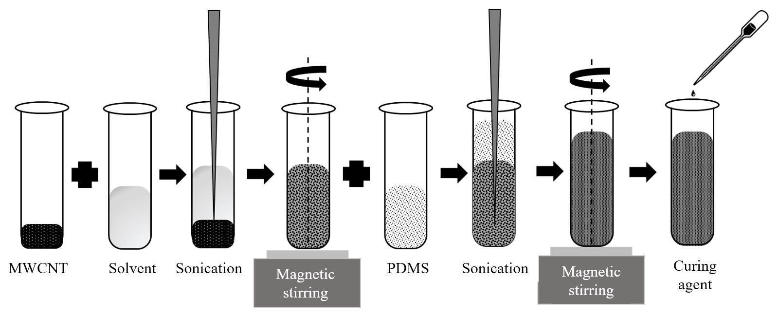
In the nanocomposite synthesis process, the MWCNTs are dispersed in PDMS based on the optimized parameters from prior work (Ramalingame et al., 2017a). MWCNTs with an outer diameter of 6–9 nm and a length of 5 µm are mixed with Sylgard 184 PDMS using tetrahydrofuran (THF) as the dispersion medium (Ramalingame et al., 2017c). MWCNTs of 1 wt % are dispersed in THF using ultrasonication with a Sonopuls HD 7300 horn sonicator for 30 min at 20 % amplitude. Total energy of 13.7 kJ is supplied to debundle the MWCNTs, followed by magnetic stirring using CAT-M26 for 60 min at 1600 rpm and 70 ∘C. The magnetic stirring provides uniform shear forces to enable homogeneous distribution of the MWCNTs in THF. Later PDMS is introduced to the dispersion and sonication for 15 min at 50 % amplitude, with a total energy of 9.6 kJ, and is magnetically stirred for 60 min at 1600 rpm and 70 ∘C. The nanocomposite is cooled for 4 h before adding the curing agent in the ratio 10:1. The complete dispersion preparation process is graphically represented in Fig. 1.
2.1.1 Sensor casting
As PDMS is a thermosetting polymer, the nanocomposite material can be mold cast into pressure sensors of desired shapes and sizes. A laser-cut PTFE mold with circular slots with a diameter of 20 mm and a thickness of approx. 500 µm is used for sensor casting (Fig. 2a); 1 g of the nanocomposite material is transferred by weight into the pre-cleaned mold. The mold is then placed in a degassing chamber to remove the trapped bubbles for 15 min. After resting for about 30 min at room temperature the mold is placed in an oven, which is preheated to 120 ∘C. After 2 h of curing, the sensors are peeled off the mold. The thickness of the mold-cast sensors varies depending on the amount of evaporation of the residue solvent and was measured to be in the range of 350 to 400 µm. The same procedure can be applied to synthesis sensors of various diameters ranging from 5 to 20 mm, as shown in Fig. 2b. The fabricated sensors are then placed on a circular interdigital electrode structure and are screen printed using silver ink on Kapton substrate that is 125 µm thick, as shown in Fig. 2c. Due to the sticky nature of the PDMS, the sensor adheres to the Kapton substrate without any addition medium, establishing good electrical contact, and the measured initial resistance of the sensor was around 4 MΩ without any pressure.
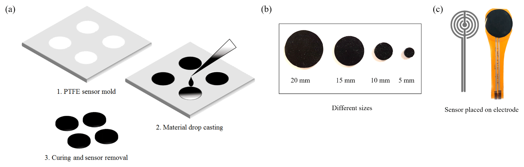
Figure 2(a) Illustration of the sensor mold-cast process steps; (b) different shapes of the diced sensor; (c) circular interdigital electrodes, screen printed with silver ink for electrical contact with sensor; and sensor placed on the electrode structure.
To investigate the piezo-capacitive behavior of the fabricated nanocomposite pressure sensors, a custom-built pressure measurement test bench interfaced with an LCR meter (Agilent 4284A precision LCR meter) is utilized as shown in Fig. 3a. The test bench is equipped with a high-resolution load cell (K307M.200) that can exert a maximum load of 200 N onto the sensor being tested. To ensure safe operation of the load cell, the maximum load applied to the sensors was limited to 180 N at a nominal speed of 0.1 N s−1. To measure the capacitance change in the sensor the LCR meter must be operated at a particular frequency that should match with the resonance frequency of the sensor. Hence, the sensor was scanned for its resonance frequency using the impedance spectroscopy analysis based on prior work (Ramalingame et al., 2017b). The plot in Fig. 3b represents the real and imaginary part of the impedance in a frequency range of 40 Hz to 100 MHz, with the resonance at 47.8 KHz. With this information, the LCR meter is set to operate in Cp−Rp mode, with an oscillation voltage of 1 V and frequency of 50 kHz.
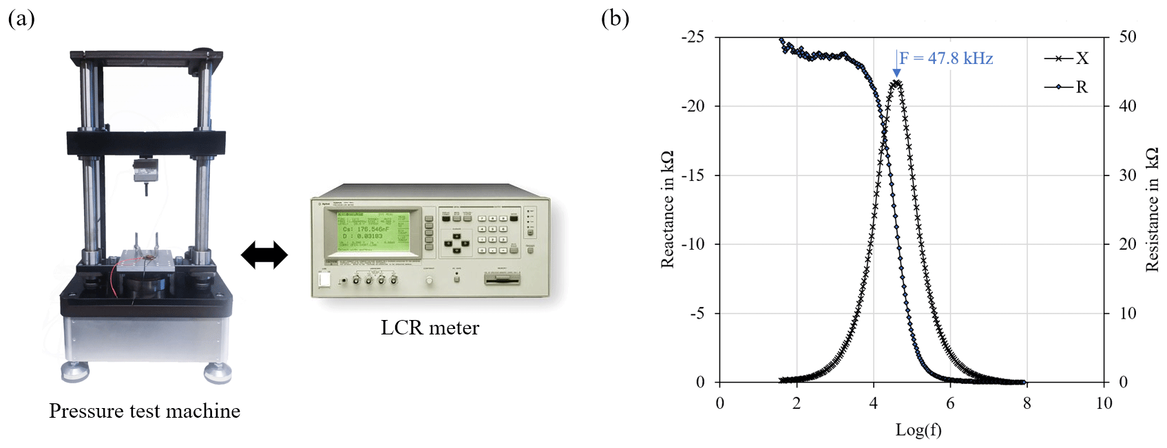
Figure 3(a) The custom-built pressure test bench used to characterize the fabricated sensor. (b) Plot representing the resonance frequency of the sensor measured using an impedance analyzer.
3.1 Measurement in small pressure range
The developed nanocomposite pressure sensor exhibits a piezo-capacitive effect under pressure. As the load increases, the measured capacitance of the sensor increases, which can be attributed to two phenomena taking place in the sensor's mechanical and electrical properties. Upon application of the load, the sensor gets compressed; (1) the distance between the MWCNTs decreases and hence the tunneling capacitance increases; and (2) more MWCNTs are moved towards the fields of the underlying electrode structures, increasing the dielectric constant of the material. In either case, the capacitance increases as the load increases. Figure 4 represents a graphical illustration of the working principle of the nanocomposite pressure sensor.
The sensor shows sensitivity in a wide pressure range with a minimum pressure sensitivity of 0.5 kPa, as shown in Fig. 5a. The initial capacitance C0 of the sensor under no load condition is around 10.5 pF. The graph presents the change in capacitance (C−C0) as a function of the applied load. Slotted weights are utilized to test the low-pressure sensing capability of the sensors ranging from 1 to 100 g, corresponding to 0.5 to 50 kPa respectively. The sensitivity of the sensor is estimated to be 25 % N−1 in the range of 0–0.5 kPa and 46.8 % N−1 in the range of 0–50 kPa (0–1 N), which is 10.9 % higher than the literature (Ji et al., 2016), with a sensitivity of 35.9 % N−1 in the range of 0–1 N.
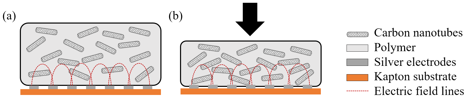
Figure 4Illustration of the working principle of the MWCNT–PDMS pressure sensor. (a) Position of MWCNTs in the polymer matrix, and electric field of the underlying electrodes under no pressure. (b) With applied pressure, the MWCNTs are pushed close together and deeper into the electric field.

Figure 5(a) Change in capacitance (C−C0) of the sensor under load from slotted weights in the range 1–100 g, and (b) capacitance response of the pressure sensor for loading and unloading to a maximum load of 180 N.
3.2 Measurement in full pressure range
The nanocomposite pressure sensor was tested in the pressure measurement test bench to evaluate the full pressure range capability of the sensor. The maximum load applied was limited to 180 N to ensure safe operation of the load cell. Thus, it was impossible to characterize the complete pressure sensing range which could be principally higher than the applied load of 180 N. The pressure sensing property of the sensor is a factor of the maximum compressibility of the material and the distance between adjacent nanofillers in the polymer matrix (Cui et al., 2016). The absolute change in capacitance is approx. 300±10 pF corresponding to the load of 180 N, which can be seen in Fig. 5b. It can also be observed from Fig. 5b that the sensor response is non-monotonic, exhibiting different sensitivity regions. This is attributed to the viscoelastic nature of the PDMS polymer, which decreases the compressibility of the sensor material beyond certain applied force (Ramalingame et al., 2019). As the material decompresses upon releasing the applied pressure, a relaxation behavior of the polymer exists which causes the material to have different compression and decompression states and in turn a hysteresis effect in the pressure cycle of the sensor. Such a hysteresis effect can be minimized either by reducing the viscoelasticity of the polymer, which could also decrease the overall sensitivity of the sensor, or by developing a signal-conditioning circuit with a modeled characteristic hysteresis curve of the sensor.
3.3 Current-voltage profile
The current-voltage (I–V) measurement was performed on the pressure sensors using a Keithley 2400 source meter in the range of −10 to +10 V. Voltage exceeding this range causes physical damage to the underlying silver electrodes. Figure 6a shows the I–V profile of the sensor with a linear region in the range of less than 2 V. The electrons in the nanofiller are freely accessible in the complete matrix, hence the conduction mechanism takes place even at very low applied forces on the sensor (Sen et al., 2016). Without any applied load or voltage, the sensor exhibits a high impedance. The maximum current consumed by the sensor in this region is 10 µA. Beyond this range, as the voltage increases, the current increases drastically, which can be attributed to the hopping mechanism of electrons between nanotubes (Zhao et al., 2015).
Such an increase in current by the hopping mechanism can also be observed as the applied pressure on the sensor increases. The increase in current with applied voltage is not linear, hence a current-pressure measurement was performed. Figure 6b represents the current-pressure behavior of the sensor with different applied voltages. The measured current is directly proportional to the applied voltage. It can also be observed from Fig. 6b that the current increases as the load increases until 40 N (Region – I), followed by a steady decrease up to 100 N (Region – II). The non-monotonic behavior of the current with the applied load is a factor of the different magnitude of the compression forces. The region of the magnitude can be divided into two categories: low forces, in this case around 40 N, and high forces, greater than 40 N. At low forces the increase in current is contributed by the change in distance between the CNTs, and at higher forces, the decrease in current is a factor of the surface area per particle on the applied force (Semeriyanov et al., 2013). The linearity of the sensor response can be split into different regions, as shown in Fig. 6c with a linear fit of R2 greater than 0.98.
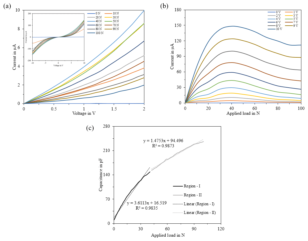
Figure 6(a) Current-voltage characteristics for different loading conditions. (b) Current-pressure characteristics for different operating voltages. (c) Region of linearity in the sensor response.
3.4 Application in robotics
The fabricated nanocomposite pressure sensors are tailored into desired dimensions that are suitable for robotics applications. The sense of touch and the gripping efficiency of a gripper robot can be enhanced by incorporating a tactile sensor array with small sensor elements in the finger of the robot. Here the need for higher sensitivity and spatial resolution is important to grasp objects of different sizes and weights. The movement of the robot is also crucial to maintain the stability and posture, hence, feedback from a pressure sensor placed under the foot of the robot can be very beneficial in tuning the motion algorithm of the robot. In this case, despite the sensitivity, sensors with a wide range of pressure sensing capabilities are advantageous, since the entire load of the robot will be transmitted to the sensor under its foot.

Figure 7(a) 4×3 tactile sensor array implementation in robotic finger. (b) Sensor response demonstrating the spatial resolution and low-pressure sensing capability.

Figure 8(a) Sensor placement in the foot of the humanoid robot for gait analysis. (b) Pressure response curve obtained by one walk cycle of the robot.
3.4.1 Tactile sensor array for robot finger grip analysis
The proposed sensor matrix consists of 12 sensor elements, each 5 mm in diameter, diced from the mold-cast 20 mm sensor. The sensor elements are arranged in 4×3 matrix layout (20 mm×15 mm) comprised of 12 circular interdigital electrode structures for an optimum contact area in the sensor. The designed array can be accessed as rows and columns by a data acquisition system. An eight-channel dual multiplexer setup is utilized to address individual sensor elements in the array and obtain the pressure response in terms of voltage output. Such a tactile sensor array can be easily attached to finger elements of any humanoid or gripper robots and could be a potential pressure sensing device in robotic fingers, with the advantage of a high spatial resolution because of the smaller sensor dimension. Figure 7a shows the nanocomposite tactile sensor array placed next to a EUR 1 coin for size comparison and a typical representative example of implementation in the robotic finger. As a preliminary study, a slotted weight of 10 g with a base diameter of 8 mm was placed in a different position of the tactile array, and the output was recorded. Figure 7b presents one such response and shows that only the sensors that are in contact with the placed weight exhibit a change in output response. The designed tactile sensor matrix, with sensor elements of 5 mm in diameter, can sense a load starting from 10 g with a spatial resolution of 5 mm in diameter.
3.4.2 Foot sensor for robot gait analysis
The fabricated nanocomposite pressure sensor with 20 mm diameter is utilized to analyze the gait of a humanoid robot. Full-size prototype humanoid robot legs serve as the test subject for gait analysis. The point of contact of the robot foot to the ground is in three distinct positions, two in the front and one at the back. The area of contact of the foot to the ground is approximately 300 mm2 in the front two segments and 75 mm2 in the rear segment. With the current stage of the prototype robot making small and gentle walking steps, the sensor is placed directly under one frontal segment of the right foot, as shown in Fig. 8a. The piezo-capacitive response of the pressure sensor was recorded in real time from a programmable Fluke RCL meter PM6304 using a Python script.
The robot was programmed to walk a distance of 1 m, which corresponds to three steps in each leg, and one such response is shown in Fig. 8b. The prototype is suspended from a support frame, and for safety reasons, the standing position of the robot is actually a hanging position. This implies that at any instant only one leg will be in contact with the ground, and when both the legs are at the same level, the robot gets suspended with no contact to the ground. The response shown in the Fig. 8b corresponds to half of one complete walk cycle, as only one leg was monitored, and the numbers along the curve denote the following:
-
0 is when the right leg is above the ground and the robot is supported by the left leg.
-
1 is when the right leg has established contact with the ground.
-
2 is when both the right and left leg are firmly placed on the ground.
-
3 is when the left leg starts to lift up and the force exerted on the right leg increases.
-
4 is when the left leg approaches the ground and the robot starts to hang.
-
0 is when the right leg is above the ground until the walking cycle of the left leg is complete.
The experiment shows that the sensor is capable of tracking physical movements of the robot and has the potential to analyze the gait of the robot. Such an analysis can provide critical information for ensuring optimal functioning of the robot in its desired application.
Pressure sensors with high sensitivity and wide pressure sensing ranges have the potential to be utilized in various applications, notably in the field of robotics. The developed nanocomposite pressure sensor has a high sensitivity of 46.8 % N−1, with a very stable response and a wide pressure sensing range from 0.5 to 570 kPa. The I–V curve provides information on the energy efficiency of the sensor, which consumes less than 10 µA of the current at the maximum load, making it suitable for continuous and long-term sensing application with less power consumption. The region of linearity of the sensor could enable simple, cost-effective signal conditioning and a data acquisition system. Such pressure sensors could be easily integrated on the fingers of robots to determine the grasping force exerted by the robot on an object, which ensures safe handling conditions. The high sensitivity and good spatial resolution enable the robot to perform precision grasping of small objects with a minimum detection size of 5 mm. Also, with the ability to withstand and sense high pressures of 570 kPa, the sensor is suitable for monitoring and analyzing the gait of humanoid robots. Such a gait analysis of robots could be used to determine performance-tuning information like the walking pattern, load distribution on the legs, posture monitoring, and correction and energy consumption of the system.
The underlying measurement data are not publicly available and can be requested from the authors if required.
RR, as the main author, synthesized the nanocomposite, developed the nanocomposite-based pressure sensors, developed the tactile sensor matrix and the sensors of robot gait analysis, performed the necessary experiments on the pressure sensors, and drafted the paper. AL participated in performing experiments on the pressure sensors. FM participated in performing experiments on the robot gait analysis. UT and OK discussed the experimental results and contributed to the paper.
The authors declare that they have no conflict of interest.
This article is part of the special issue “Sensors and Measurement Systems 2018”. It is a result of the “Sensoren und Messsysteme 2018, 19. ITG-/GMA-Fachtagung”, Nuremberg, Germany, from 26 June 2018 to 27 June 2018.
The research work is carried out under the “Landesinnovationsstipendium
(100284169)”, funded by the Sächsische Aufbaubank (SAB) and the European
Social Fund (ESF).
Edited by: Nam-Trung Nguyen
Reviewed by: two anonymous referees
Cao, Y., Li, T., Gu, Y., Luo, H., Wang, S., and Zhang, T.: Fingerprint-inspired flexible tactile sensor for accurately discerning surface texture, Small, 14, 1703902, https://doi.org/10.1002/smll.201703902, 2018. a
Chen, L., Liu, J., Wang, X., Ji, B., Chen, X., and Yang, B.: Flexible capacitive hydrogel tactile sensor with adjustable measurement range using liquid crystal and carbon nanotubes composites, IEEE T. Electron Dev., 64, 1968–1972, https://doi.org/10.1109/TED.2017.2682099, 2017. a
Cui, J., Zhang, B., Duan, J., Guo, H., Tang, J., Cui, J., Zhang, B., Duan, J., Guo, H., and Tang, J.: Flexible pressure sensor with ag wrinkled electrodes based on PDMS substrate, Sensors, 16, 2131, https://doi.org/10.3390/s16122131, 2016. a, b
Dinh, T., Nguyen, T., Phan, H., Fastier-Wooller, J., Tran, C., Nguyen, N., and Dao, D. V.: Electrical Resistance of Carbon Nanotube Yarns Under Compressive Transverse Pressure, IEEE ELECTR DEVICE L, 39, 584–587, https://doi.org/10.1109/LED.2018.2806181, 2018. a
Emon, M., Choi, J.-W., Emon, M. O. F., and Choi, J.-W.: Flexible piezoresistive sensors embedded in 3d printed tires, Sensors, 17, 656, https://doi.org/10.3390/s17030656, 2017. a
Fastier-Wooller, J., Dinh, T., Dau, V.T., Phan, H.-P., Yang, F., and Dao, D. V.: Low-Cost Graphite on Paper Pressure Sensor for a Robot Gripper with a Trivial Fabrication Process, Sensors, 18, 3300, https://doi.org/10.3390/s18103300, 2018. a
Jain, S. and Bhatia, D.: A novel design of tactile sensor using piezoresistive cantilever for robotic application, IEEE 7th Power India International Conference (PIICON), 25–27 November, 1–5, https://doi.org/10.1109/POWERI.2016.8077264, 2016. a
Ji, Z., Zhu, H., Liu, H., Liu, N., Chen, T., Yang, Z., and Sun, L.: The design and characterization of a flexible tactile sensing array for robot skin, Sensors-Basel, 16, https://doi.org/10.3390/s16122001, 2016. a, b
Li, X., Huang, W., Yao, G., Gao, M., Wei, X., Liu, Z., Zhang, H., Gong, T., and Yu, B.: Highly sensitive flexible tactile sensors based on microstructured multiwall carbon nanotube arrays, Scripta Materialia, 129, 61–64, https://doi.org/10.1016/j.scriptamat.2016.10.037, 2017. a
Nag, A., Menzies, B., and Mukhopadhyay, S. C.: Performance analysis of flexible printed sensors for robotic arm applications, Sens. Actuat. A, 276, 226–236, https://doi.org/10.1016/j.sna.2018.04.031, 2018. a
Nela, L., Tang, J., Cao, Q., Tulevski, G., and Han, S.-J.: Large-area high-performance flexible pressure sensor with carbon nanotube active matrix for electronic skin, Nano Lett., 18, 2054–2059, https://doi.org/10.1021/acs.nanolett.8b00063, 2018. a
Ramalingame, R., Rajendran, D., and Kanoun, O.: Method optimization of MWNCT/PDMS nanocomposites using organic solvents, Printed Future Days 2017, 4–6 October, Chemnitz, 121–125, 2017. a
Ramalingame, R., Torres, R., Hu, Z., Chandraker, P., and Kanoun, O.: Electrical impedance analysis on nanocomposite based pressure and strain sensors, 10th International Workshop on Impedance Spectroscopy (IWIS), 26–28 September, Chemnitz, 102–103, 2017. a
Ramalingame, R., Chandraker, P., and Kanoun, O.: Investigation on the Influence of Solvents on MWCNT-PDMS Nanocomposite Pressure Sensitive Films, Proceedings, 1, 384, https://doi.org/10.3390/proceedings1040384, 2017. a
Ramalingame, R., Hu, Z., Gerlach, C., Rajendran, D., Zubkova, T., Baumann, R., and Kanoun, O.: Flexible piezoresistive sensor matrix based on a carbon nanotube PDMS composite for dynamic pressure distribution measurement, J. Sens. Sens. Syst., 8, 1–7, https://doi.org/10.5194/jsss-8-1-2019, 2019. a, b
Sen, T., Mishra, S., and Shimpi, N. G.: Synthesis and sensing applications of polyaniline nanocomposites: a review, RSC Adv., 6, 42196–42222, https://doi.org/10.1039/C6RA03049A, 2016. a
Semeriyanov, F. F., Chervanyov, A. I., Jurk, R., Subramaniam, R., König, S., Roscher, M., Das, A., Stöckelhuber, K. W., and Heinrich, G.: Non-monotonic dependence of the conductivity of carbon nanotube-filled elastomers subjected to uniaxial compression/decompression, J. Appl. Phys., 113, 103706, https://doi.org/10.1063/1.4794835, 2013. a
Wang, H.: Development of a conformable electronic skin based on silver nanowires and PDMS, IOP Conf. Ser. Mater. Sci. Eng., 207, 012040, https://doi.org/10.1088/1757-899X/207/1/012040, 2017 a
Zhang, J., Zhou, L. J., Zhang, H. M., Zhao, Z. X., Dong, S. L., Wei, S., Zhao, J., Wang, Z. L., Guo, B., and Hu, P. A.: Highly sensitive flexible three-axis tactile sensors based on the interface contact resistance of microstructured graphene, Nanoscale, 10, 7387–7395, https://doi.org/10.1039/C7NR09149D, 2018 a
Zhao, Y., Sugunan, A., Wang, Q., Yang, X., Rihtnesberg, D. B., and Toprak, M. S.: Direct determination of spatial localization of carriers in cdse-cds quantum dots, J. Nanomater., 2015, 321354, https://doi.org/10.1155/2015/321354, 2015. a