the Creative Commons Attribution 4.0 License.
the Creative Commons Attribution 4.0 License.
 | 20 Aug 2020
Determination of the mean base circle radius of gears by optical multi-distance measurements
Marc Pillarz
Axel von Freyberg
Andreas Fischer
The required reliability of wind turbine gearboxes increases the requirements for large gear measurements. Extensive measurements to reliably assess the geometry of large gears in the single micrometer range are necessary. Due to an individually fixed measuring volume, standard methods like coordinate and gear measuring instruments reach their limits for large gears with diameters > 1 m. Therefore, a scalable optical measurement approach consisting of a single sensor in combination with a rotary table for multi-distance measurements with subsequent model-based evaluation of shape parameters of gears is presented. The scalable measurement approach is to be extended to a multisensory system in further work. As a fundamental shape parameter the mean base circle radius using the example of spur gears is determined. The base circle radius is used due to the geometric relationship to further shape parameters for example to the profile slope deviation. The theoretically achievable measurement uncertainty of the mean base circle radius due to sensor noise is estimated to less than 5 µm (k=2) for a small and a large gear, which verifies the scalability of the sensor system. In order to show a general proof of principle, two series of optical measurements on a gear with a diameter of 0.105 m are performed and referenced with a tactile measurement. As a result, random errors of 1.2 µm for k=2 are determined. The remaining systematic deviations to the reference value amount to 4.3 and 1.6 µm, respectively. Hence, the total measurement uncertainty is currently limited by systematic effects, and the defined aim of a total uncertainty of less than 5 µm (k=2) is narrowly missed by 1.5 µm. The random errors of 1.2 µm (k=2) show, however, that an adequate measurement precision is achieved and that the multi-distance measurement approach has the potential to reach the aimed measurement uncertainty with appropriate strategies to compensate for the systematic influences. The experimental and theoretical results prove the principle applicability of the proposed single sensor multi-distance approach for the precise inspection of gears.
- Article
(1278 KB) - Full-text XML
- BibTeX
- EndNote


1.1 Motivation and measurement requirements
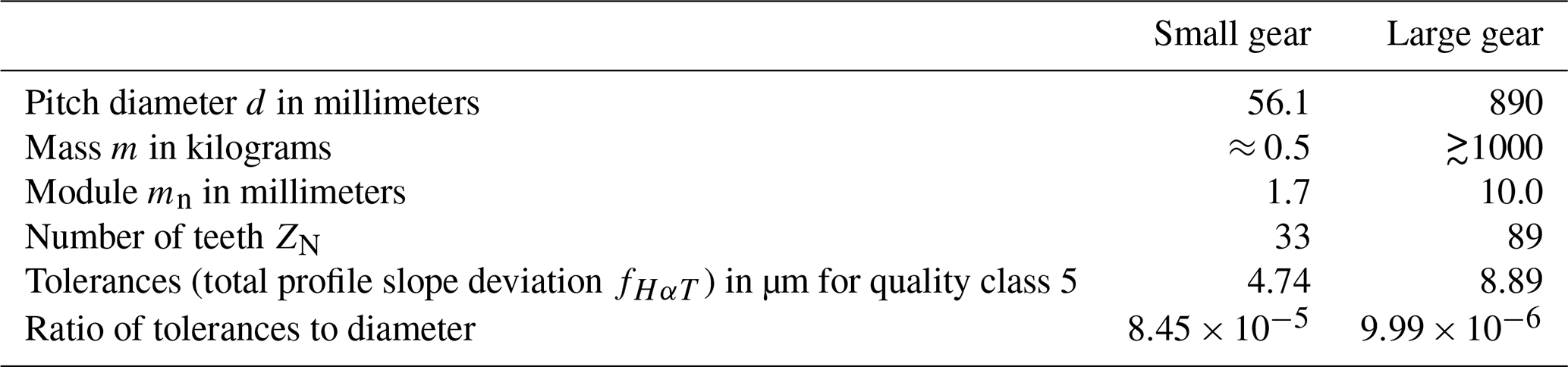
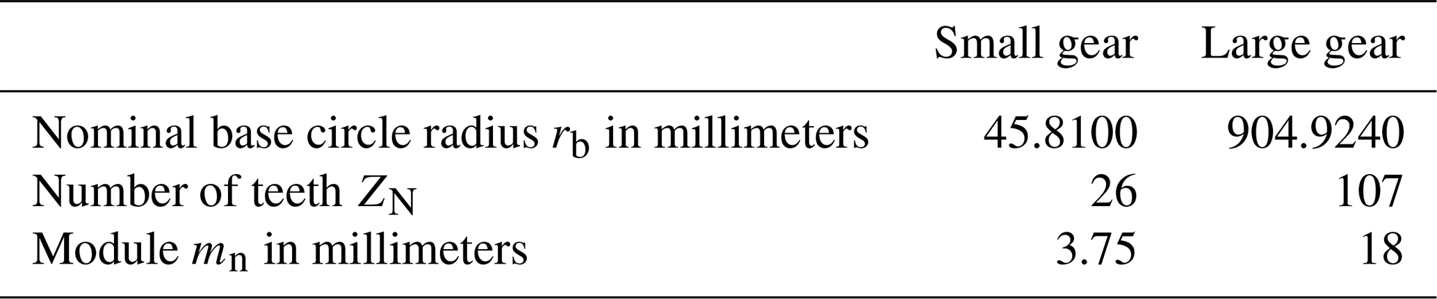
Around 90 % of the drive trains of installed wind turbines are based on gearboxes with diameters of 1 m (Crowther et al., 2011). To improve the reliability of the gearboxes, extensive measurements of the geometry of each tooth are required (Balzer et al., 2015; Goch et al., 2012). With increasing diameter and module of the gear, the ratio of the required measuring uncertainty to the measuring volume decreases, although the tolerances increase; cf. Table 1. So, the required dynamic range of the measuring system is constantly increasing with increasing gear sizes (Schmitt et al., 2016). Hence, measurements of shape parameters of large gears with diameters > 1 m or modules > 10 mm with an uncertainty of single-digit micrometers are necessary to comply with the golden rule of metrology. Due to the size and mass of large gears listed in Table 1, the quality inspection of the gear geometry is also associated with a higher logistical effort when bringing the gear to the measurement system, in comparison to gears with diameters < 1 m. For this reason, mobile and scalable gear measurement systems are desirable to quantify the shape parameters of the gears with single-digit micrometer uncertainty with reduced logistical effort.
Table 1Parameters of a small gear compared to the parameters of a large gear according to ISO 1328-1 (2013).
1.2 State of the art
The current state of the art for measuring the geometry of large gears is considered with the two-criteria measurement uncertainty and logistical effort in terms of mobility and scalability of the measurement system. Coordinate measuring machines (CMMs) and gear measuring instruments (GMIs) with a tactile sensor with a maximum permissible error of µm (L = measured length in millimeters) are the standard systems to measure the geometry of gears (Balzer et al., 2017; Franceschini et al., 2014; Peggs et al., 2009). CMMs with measuring volumes of up to 5 m × 11 m × 3.5 m and µm (Dussling, 2010) enable high dynamic ranges. At the same time they consist of stable and heavy materials (Peggs et al., 2009), and the measuring volume cannot be scaled up. Thus, the geometry measurement of large gears is associated with a high logistical effort with regard to the transport of the measured object to the measuring system. CMMs and GMIs with tactile sensors are only conditionally suitable for extensive measurements of the geometry of large gears.
The acquisition of coordinates by a frequency-modulated interferometric sensor is another approach for gear measurements and is presented in Balzer et al. (2015). The beam path is guided fiber-optically into a sensor head, which is moved by the coordinate measuring machine. Currently, no frequency-modulated interferometric sensor approach without a CMM-based movement is known for gear measurements. Thus, it can neither be scaled up nor used for mobile measurements. Because of the high logistical effort, CMMs and concepts based on CMMs are not applicable for extensive large gear measurements.
Alternative measuring approaches for large gears can be found in the field of large-volume metrology. Generally, large-volume metrology follows the paradigm of bringing the measuring system to the target (Franceschini et al., 2011), which enables mobile and scalable measurement setups compared to CMMs. Setups of laser trackers, based on interferometric distance measurements, are used in the field of multilateration for precise measurements (Ibaraki et al., 2012), for example, for the calibration of large CMMs (Gąska et al., 2014). These setups achieve distance measurement uncertainties <1 µm (Muralikrishnan et al., 2016), but only when special reflectors are attached to the surface to be measured. Laser trackers are therefore not suitable for measuring the geometry of large gears. Further large-volume metrology approaches like portable articulated arm coordinate systems (Cuesta et al., 2012; Härtig et al., 2012), laser radar systems, theodolites, or indoor GPS (Peggs et al., 2009) cannot meet the required single-digit uncertainty for large gear measurements. Therefore, measurement approaches, which follow the paradigm of large-volume metrology, are not suitable for extensive large gear inspections.
Optical approaches based on triangulation are introduced in Younes et al. (2005), Meeß et al. (2006) and Auerswald et al. (2019) and can perform point-by-point, linear (Gestel et al., 2009; Auerswald et al., 2019) or area-oriented measurements (Zhang, 2010). In 2005, Younes et al. (2005) investigated a triangulation laser for the geometric detection of gears, but the required measurement uncertainty to assess the desired tolerances of the profile slope deviation was not achieved. Laser line triangulation sensors have great potential for rapid large gear inspections. At present, laser line triangulation approaches for large gears attain measurement uncertainties of the profile slope deviation of 8.2 µm, so that the required measurement uncertainty is not achieved. In addition, multiple reflections of the laser beam on the tooth flank surface lead to measurement artifacts that also influence the measurement uncertainty (Auerswald et al., 2019). An area-oriented approach for extensive gear measurements like stripe pattern projection is introduced in Meeß et al. (2006). However, measurement uncertainties of >10 µm occur for gear parameters like the profile slope deviation, which is not in agreement with the required uncertainty. In summary, no measurement approach for extensive large gear inspections with a mobile and scalable measuring volume with a single-digit micrometer uncertainty exists to quantify the gear shape parameters to date.
1.3 Aim and structure of the article
A novel, scalable multi-distance measurement concept to quantify shape parameters of large gears with single-digit µm uncertainty is presented. The measuring approach consisting of an optical single sensor in combination with a rotary table is initially designed for small spur gears and is to be supplemented in further work with additional sensors to form a multisensory system. Due to the geometric correlation of the base circle radius with further shape parameters, for example with the profile slope deviation, the base circle radius is used as a fundamental shape parameter. According to this correlation and with regard to the golden rule of metrology and the required tolerances of the profile slope deviation, a measurement uncertainty of the base circle radius of less than 5 µm (k=2) is required for example for a large gear with a module of 10 mm. The methodology and the experimental setup are described in Sect. 2. By simulating the measurements, the achievable uncertainty under the aspect of a scalable measurement volume is estimated and the measuring principle is verified in Sect. 3. The general proof of principle of the scalable multi-distance measuring approach then follows in Sect. 4 on the basis of experiments. In Sect. 5, the conclusion of the article is presented. Section 6 closes the article with an outlook.
2.1 Geometric model and inverse problem
To characterize an actual mean base circle radius of spur gears, points are measured on the tooth flanks. The contour of a spur gear with an involute profile can be described depending on the base circle radius by means of a geometric model according to Goch (2003), Günther et al. (2001) and Stöbener et al. (2011). The z coordinate can be neglected here, since the measurement is made in the transverse section of the gear. Figure 1 shows the geometry of a gear in the transverse section.
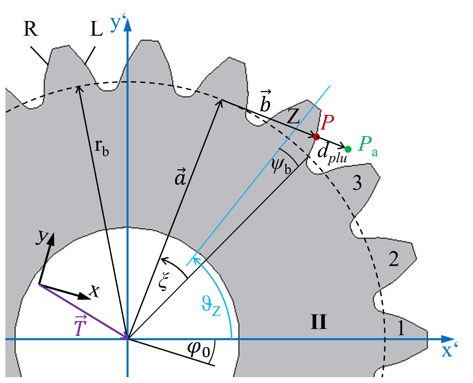
Figure 1Geometric model of a spur gear for the determination of the base circle radius rb, based on a measuring point Pa, the root point P for the plumb line distance dplu and the corresponding rolling angle ξ within the workpiece coordinate system (x′, y′).
According to Fig. 1, the nominal position (x′, y′) of a point
on the surface of tooth Z can be determined by a vector addition of radial a and tangential b components in the workpiece coordinate system (x′, y′). The radial vector a has a length of the base circle radius rb and an angle of . The length of b, the tangential vector, is rb⋅ξ, with the corresponding angle of . The angle ξ describes the rolling angle assigned to the point P′, ϑz is the angle of the position of the center axis of a tooth Z, and ψb defines the base tooth-thickness half angle. Since a measured point is detected in the measurement coordinate system (x, y), a translation vector and a rotation angle φ0 to the workpiece coordinate system must be added:
In order to characterize the base circle radius, the inverse problem of must be solved. However, since the two equations in Eq. (2) contain five free parameters (rb, xt, yt, φ0, ξ), an under-determined system of equations exists.
2.2 Solution of the inverse problem
To solve the inverse problem and to obtain the base circle radius, more points Pi with i=1 … N of the tooth flank are required to obtain a determined system of equations, i.e.,
A multi-distance measurement approach consisting of a single sensor and a rotary table for measuring the geometry of spur gears is introduced in Fig. 2. As a single sensor an optical distance sensor is used to characterize the geometry of the tooth flanks. The sensor is aligned tangentially to the nominal base circle in the transverse section of the gear and measures the distance to the surface of a tooth flank.
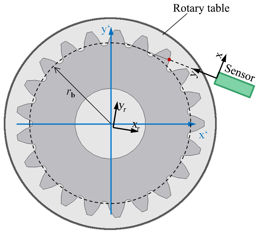
Figure 2Multi-distance measurement principle consisting of a single distance sensor (x, y) in combination with a rotary table (xr, yr) measuring continuously the surface of a spur gear (x′, y′) depending on the rotation angle.
By calibrating and adjusting the sensor system in position and alignment, the measured distance information is transformed into coordinates in a measurement coordinate system (MCS). The single sensor concept allows a continuous distance measurement depending on the angle of rotation over all teeth, and a mean base circle radius can be determined. Due to the continuous distance measurement, an overdetermined system of equations exists. The resulting information, for example, could be used to derive several shape parameters or the positioning of the center of the gear and a self-calibration of the sensor system. In this article, however, the aim is to determine a mean base circle radius with an uncertainty of less than 5 µm to show the general proof of principle of the multi-distance measurement approach.
The actual coordinates
acquired during the single sensor measurement deviate from the nominal geometry of the gear. For the calculation of the base circle radius, Eq. (3) must be extended by a plumb line distance di,plu as shown in Fig. 1. The parameter n describes the normal vector of the surface at the measured point which points in the same direction as the plumb line distance for spur gears. In order to determine the mean base circle radius, an ideal involute is approximated into the measuring points using the least squares method. First, a function for the plumb line distance di,plu is established according to (Günther et al., 2001; Stöbener et al., 2012)
where
describes the radius of the measured point in polar coordinates within the workpiece coordinate system and
defines the corresponding polar angle to ri,I. “fladir” defines a factor for the flank side, −1 for the left-hand side and 1 for the right-hand side. In addition to the base circle radius, the transformation parameters xt, yt and φ0 are unknown and must be calculated iteratively, while the gear parameters ϑz and ψb are known due to the geometry of the gear. The optimal involute in workpiece coordinates is found by minimizing the sum of the squared distances di,plu related to the measured data, according to the least squares method:
Corresponding to the approximated involute, the free parameter actual base circle radius and the transformation parameters between workpiece and measurement coordinate system are determined.
2.3 Experimental setup
The experimental setup of the multi-distance measurement system is shown in Fig. 3. For the optical distance measurement, a confocal-chromatic sensor (CCS) IFS2405-10 from MicroEpsilon is used. The sensor has a measurement range of 10 mm with an experimentally determined uncertainty for distance measurements of approx. uCCS=0.3 µm for k=1. In order to prove the general suitability of the measurement approach, a small spur gear is used due to a simpler handling. Further, a production-oriented measuring strategy is chosen to characterize the manufacturing tolerances of the gear. The gear has 26 teeth with an involute profile, a module mn=3.75 mm and a nominal base circle radius of mm. As rotary unit, the rotary table of a Leitz PMM-F 30.20.7 portal coordinate measuring machine is used. The gear is mounted on the rotary table at the level of the sensor by means of a clamping unit.
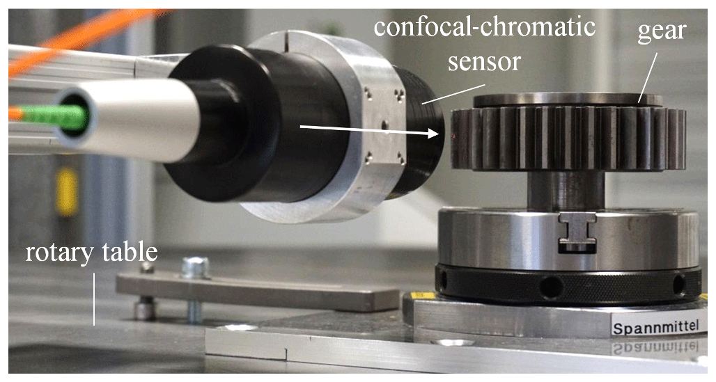
Figure 3Experimental setup of a multi-distance measurement of the mean base circle radius of a spur gear.
A major challenge in this setup is the concentric mounting of the gear with the center of rotation. A wobbling of the gear due to an oblique clamping cannot be neglected either and is overlaid by a wobble of the rotary table of the Leitz PMM-F 30.20.7. In order to demonstrate an initial proof of principle of the measuring concept, the Leitz CMM with a probing error of uCMM=0.8 µm is used as a calibration environment to compensate for the effects of the wobbles. Note that the MPEE is not taken into account here, as the length-dependent uncertainty contribution is very small due to the dimensions of the gear.
First, the sensor is determined in its position and orientation to configure a MCS according to the measurement axis of the CCS. The origin of the MCS is positioned at the beginning of the measurement range of the sensor with an uncertainty of ux=1.1 µm, uy=1.2 µm and uz=1.1 µm for k=1. The sensor alignment is defined in the negative x direction. The uncertainty of the sensor alignment (α: rotation around the z axis; β: rotation around the y axis) is uα≈0.05∘ and uβ≈0.05∘ for k=1. Using the information of the adjustment, the measured distances si to the tooth flank can be converted into MCS coordinates , 0, 0). The measuring points are then transferred to a previously calibrated rotary table coordinate system (RCS)
and must be rotated according to their corresponding rotation angle in order to obtain the contour of the tooth flanks. The vector Ts describes the translation of the sensor coordinates into rotary table coordinates. Rs is the corresponding rotation matrix around the three coordinate axes. The rotation matrix Ri defines the rotation movement of the rotary table around the z axis of the RCS. In order to compensate for the influence of the wobble, the measurement data are then transformed into the workpiece coordinate system:
For this reason, a tactile reference measurement with the Leitz PMM-F 30.20.7 is carried out in addition to the optical measurement of the gear. This measurement can be used to determine the spatial orientation and position of the gear relative to the center of the rotary table. Analogously to Eq. (9), the parameter Tw represents the displacement into the workpiece coordinate system and Rw represents the corresponding rotation matrix. The measurement data are then projected into the x–y plane and can be solved iteratively with Eq. (8) using the Newton method.
For the validation of the determined actual mean base circle radius, a reference value is needed. Based on the following context, a reference mean base circle radius
can be determined by means of the shape parameter mean profile slope deviation of all teeth which depends on the evaluation range Lα and the nominal base circle radius rb,n. The profile slope deviation defines the deviation of the actual slope in comparison with the nominal slope of an involute without influence of form deviations (Linke et al., 2016). The parameter for the corresponding evaluation range is determined by the tactile reference measurement from 5512 points over all teeth. To characterize the suitability of the single sensor system, the evaluation range is equal to the optically measured points on the surface of the gear. A reference value for the mean base circle radius can then be calculated. All measurements are performed in an air-conditioned measuring room with temporal temperature changes of less than 0.6 K per 4 h.
To verify the multi-distance measurement concept, the actual mean base circle radius with the corresponding random errors of spur gears (cf. Table 2) is determined by Monte Carlo simulation for n=1000 repetitions depending on various sensor uncertainties us.
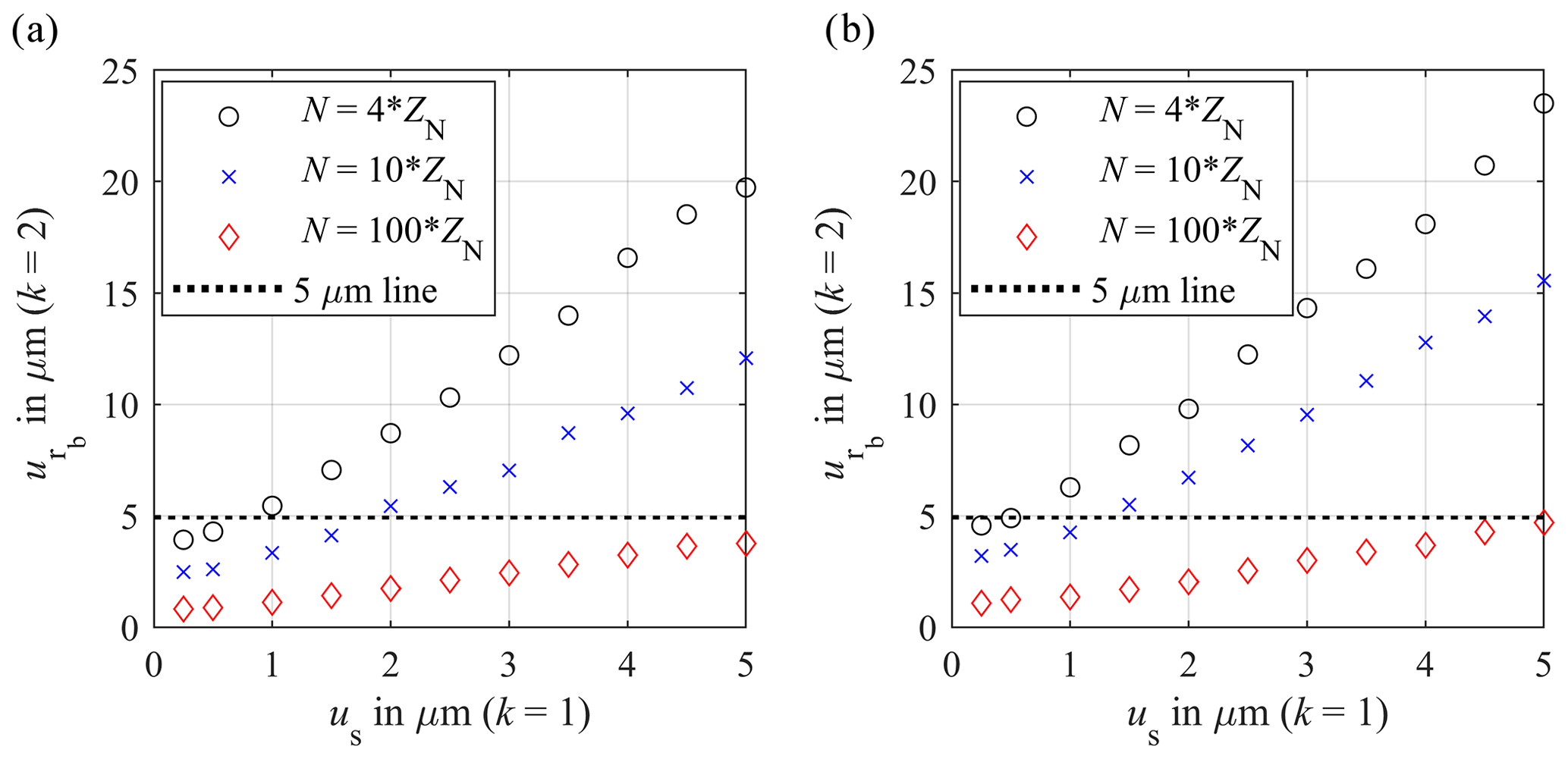
Figure 4Random error of the mean base circle radius for the single sensor approach for k=2 for (a) a small gear with a nominal base circle radius of 45.810 mm and 26 teeth and (b) a large gear with a nominal base circle radius of 904.924 mm and 107 teeth depending on the sensor uncertainty (k=1) and number of measuring points N in comparison with the required uncertainty of 5 µm (k=2).
Table 2Gear parameters of a small and large gear for the determination of the mean base circle radius by means of Monte Carlo simulation.
The sensor uncertainty us is increased stepwise from 0.25 to 5 µm and added as normally distributed noise with the standard deviation us to the simulated distances. The number of measuring points per tooth is varied by 4, 10 and 100 and multiplied by the number of teeth ZN to get the total number N of measuring points. The simulated measurement range of the optical distance sensors to the flank surface for the small gear is limited to 10 mm and based on the experimental conditions (cf. Sect. 2.3). To simulate a realistic measurement, the measurement range for the large gear is increased to 50 mm, so that a large area of the involute can be measured. However, the relative detected range of the flank is still 7 % smaller than the relative detected range of the flank of the small gear and a simulated sensor with a measurement range of 10 mm. Furthermore, a sensor alignment inclined in the x–y plane around the z axis is assumed for the simulations. Due to the shadowing by a previous tooth, the measuring points are simulated at the outer area of the involute. The gear models are also positioned eccentrically to the axis of rotation. The uncertainties of the adjustment are estimated on the basis of the experiment to ux=1 µm, uy=1 µm and uz=1 µm for the position and uα=0.05∘ and uβ=0.05∘ for the alignment around the z and y axes for k=1. Analogously to the sensor uncertainty, the adjustment uncertainties are added as normally distributed noise with the corresponding standard deviation to the coordinates. As a result, the random error of the mean base circle radius for the single sensor system for multi-distance measurements for both simulated gears depending on the sensor noise up to 5 µm is depicted in Fig. 4 for k=2. The required uncertainty for the base circle radius of 5 µm (k=2) is also shown as dotted line.
A linear correlation between the sensor uncertainty and the resulting uncertainty of the mean base circle radius can be seen, which turns into an asymptotic trend for sensor noises us<1 µm due to the influence of the adjustment uncertainty. With increasing sensor noise, the random error of the base circle radius for both simulated gears increases. Also, the random error influence decreases with an increasing number of measuring points. With a simulated uncertainty of 0.25 µm, the minimum random error for the base circle radius of the small gear is 3.92 µm for 4 measuring points per tooth flank, 2.48 µm for 10 measuring points per tooth flank and 0.82 µm for 100 measuring points per tooth flank (each for k=2). From a sensor uncertainty of 1 µm, the uncertainty of the base circle radius for four measuring points increases by 3.57 µm per 1 µm sensor uncertainty to a maximum value of 19.73 µm (k=2) for a sensor uncertainty of 5 µm. In comparison, the increase in the random error of the base circle radius for 10 measuring points is reduced to approx. 2 µm per an increase of 1 µm sensor noise. The maximum estimated uncertainty for a sensor noise of 5 µm is 12.06 µm. If the number of measuring points per flank is increased to 100, the random error for the base circle radius increases by only 0.66 µm per 1 µm sensor noise. The maximum random error for the base circle radius is approx. 3.76 µm (k=2) for 100 measuring points. If the number of measuring points per tooth flank is increased from 4 to 100, a reduction of the base circle radius uncertainty of approx. 80 % can be achieved independently of the sensor noise. In comparison to the small gear, the minimum base circle radius uncertainty of the large gear is 4.56 µm for 4 measuring points per tooth flank, 3.18 µm for 10 measuring points per tooth flank and 1.08 µm for 100 measuring points per tooth flank (each for k=2). In comparison to the small gear, the pitch diameter of the large gear is larger by a factor of 20, but the random error of the base circle radius only increases by a maximum factor of 1.31. The scaling of the gear has just a minor influence to the minimum estimated random error of the base circle radius. However, it has to be noticed that the overall number of measuring points for the large gear increases by a factor of 5. The increase in the random error of the base circle radius depending on the sensor noise is also slightly influenced by the scaling of the gear. For four measuring points, the uncertainty of the base circle radius increases by 3.98 µm per 1 µm sensor noise. The maximum value of the base circle radius uncertainty is estimated to 23.5 µm (k=2) for a sensor noise of 5 µm. For 10 measuring points, the increase in the random error of base circle radius per 1 µm sensor noise is reduced to 2.68 µm. With a sensor noise of 5 µm, the uncertainty for the base circle radius for 10 measuring points per flank is calculated to 15.54 µm (k=2). If the number of measuring points per tooth increases to 100, the uncertainty of the base circle radius is raised by 0.78 µm per 1 µm sensor noise. The maximum random error for the base circle radius is 4.7 µm (k=2) for 100 measuring points and a sensor noise of 5 µm. Compared to the small gear, an increase in the number of measuring points per tooth flank from 4 to 100 reduces the base circle radius uncertainty by 75 % to 80 %, depending on the sensor noise. As a result, the simulations show that the required uncertainty for the base circle radius of 5 µm (k=2) can be achieved from four measuring points per tooth with sensor noises up to 0.5 µm independent of the scaling of the gear. If the number of measuring points per tooth is increased to 100 or more, sensor uncertainties up to 5 µm (k=1) will be accessible. In the next step, the systematic error due to the iterative calculation of the actual mean base circle radius of an ideal involute is considered. The results are shown in Table 3.
Table 3Systematic deviations for the small Δrb,S and large gear Δrb,L depending on both the base circle radius and the number of measuring points N.
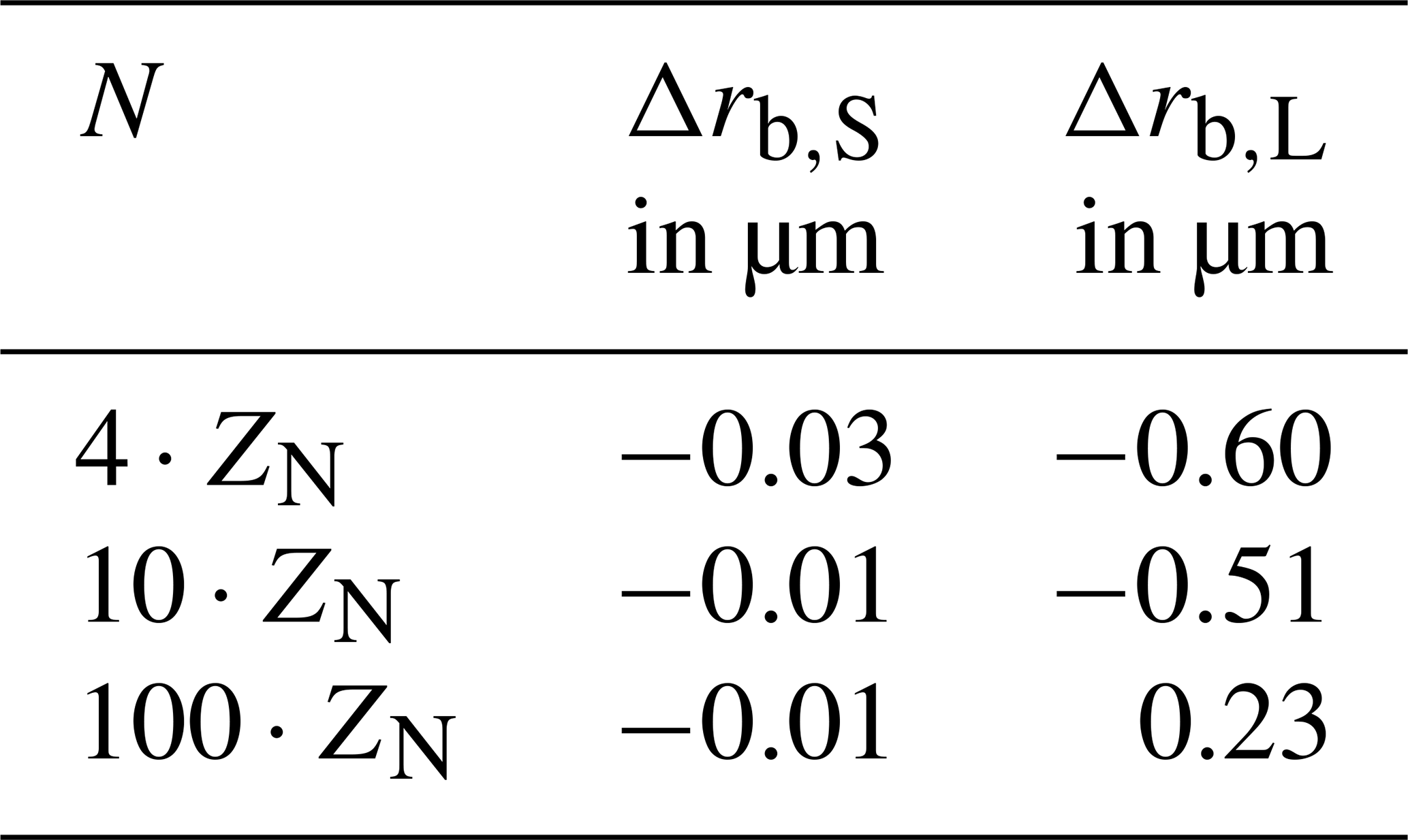
In this simulation setup the systematic error of the small gear Δrb,S fluctuates in a magnitude of one-hundredth of a micrometer and decreases by 66 % for an increase in the measuring points by a factor of 25. In comparison, the systematic deviations of the large gear Δrb,L due to the iterative approximation of the mean base circle radius are greater by 1 order of magnitude and decrease by 61 % with increasing measuring points from 4 to 100 points per tooth. An influence of the scaling of the gear can be seen. For large gears, the iterative error must be taken into account depending on the number of measurement points and the sensor uncertainty. The iterative errors for small gears do not significantly contribute to the measurement uncertainty. As a result, despite a combined measurement uncertainty of random and systematic errors for the single sensor measurement system, the required measurement uncertainty of the base circle radius is achieved. The multi-distance approach for large gear measurements is initially verified.
A reference value for the mean base circle radius is calculated from a tactile reference measurement with the Leitz PMM-F 30.20.7 CMM. According to the optical accessibility of the multi-distance measurement system, a mean profile slope deviation of N=5512 measuring points is determined. According to Eq. (11) and the international guide to the expression of uncertainty (JCGM, 2008), the reference mean base circle radius results in mm (k=2). The actual mean base circle radius is determined as described in Sect. 2.3 from the distance information of the sensor of the multi-distance measurement system transformed into coordinates for two measurement series. However, due to the eccentric clamping of the gear, different curvature ranges of the involute were recorded depending on the angle of rotation. Shape deviations of the tooth flank depending on the rolling angle lead to systematic deviations. For the evaluation of the actual mean base circle radius and comparability with the tactile measurement, the largest area of the involute common to all teeth is considered. Compared to the simulations, the evaluation range shrinks by 50 %. The number of measurement points per tooth flank amounts to 480. The corresponding random error is also calculated using Monte Carlo simulation for n=1000 repetitions. As in Sect. 3, a normally distributed noise with a standard deviation uCCS=0.3 µm for k=1 corresponding to the sensor uncertainty is added to the measured distances. The uncertainties resulting from the adjustment for the positioning (x, y, z) and alignment (α: rotation around the z axis; β: rotation around the y axis) of the sensor are estimated to ux=1.1 µm, uy=1.2 µm, uz=1.1 µm, uα≈0.05∘ and uβ≈0.05∘ for k=1. The actual mean base circle radii for the two measurement series (I and II) are then determined to
for k=2. The random errors µm for k=2 agree with the order of magnitude of the simulated random error for us=0.25 µm and depicted in Fig. 4a. In addition, deviations to the reference value of µm and µm are quantified. Considering the random errors of the reference base circle radius and the determined actual mean base circle radii, the quantified deviations are assumed to result from systematic errors.
A two-sample means test with inhomogeneous variances with an error probability of αp=0.05 is performed (Welch, 1947) to check whether these are systematic deviations from the reference value. The test variable for the test statistic is calculated by
to and .
The numerator consists of the difference of the mean values of and . σv is the standard deviation , which is estimated from nv=1000 simulations. The standard deviation σw describes the uncertainty of the actual mean base circle radius of measurement series I or II for nw=1000 simulations. The degree of freedom of the statistic is calculated based on the Satterthwaite equation (Satterwhaite, 1946). The two sided symmetric confidence interval [−c, c] for a significance level of 95 % is then [−1.960, 1.960]. It can be seen that the actual mean base circle radius for both measurement series is not in agreement with the confidence interval for a significance level of 95 %. Therefore, a systematic deviation is assumed with a probability error of 5 %.
The aspect of systematic influences is illustrated in Fig. 5. In addition to the tactile measurement data, the optically detected coordinates of the flank surface for a tooth are displayed. The optically detected involutes scatter reproducibly in an order of magnitude of 10 µm around the reference flank. An offset between and also indicates a systematic influence. Due to the order of magnitude of the scattering of 10 µm, it cannot be assumed that the scattering represents the roughness of the surface which is characterized by a mean roughness index Ra=0.45 µm. The cause of the reproducible scattering could rather be a superposition of several effects. Figure 6a depicts the measured distances of the two measurement series depending on the rotation angle for one tooth. In theory, a linear relationship between the distance to the tooth flank and the rotation angle is expected.
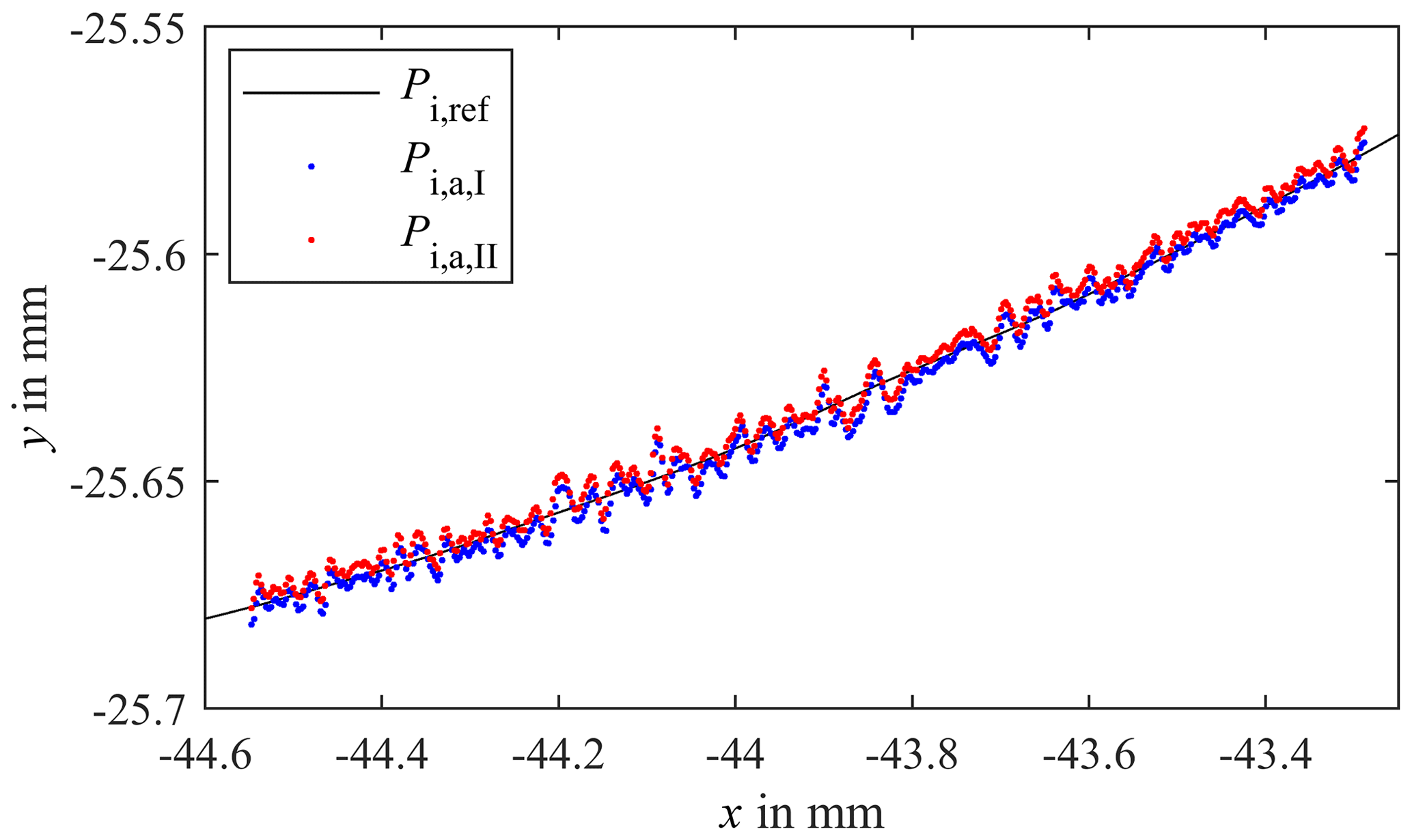
Figure 5Tactile probed points Pi,ref of one tooth in comparison with the optical transformed points Pi,a for two series of measurements.
Figure 6a shows that the measured distances decrease mostly linear with increasing angle of rotation. Merely at the root of the flank the distance measurement fluctuates and smaller distances are detected compared to distances at a correspondingly larger rotation angle; cf. Fig. 6b. The distance drops correlate with a decreasing intensity of the sensor signal due to a more difficult accessibility at the root of the flank and a larger angle of the sensor to the surface normal. Also, the susceptibility of optical measuring systems to multiple reflections from adjacent tooth flanks leads to a lower signal-to-noise ratio (Auerswald et al., 2019). However, for the evaluation of the base circle radius, these areas were not considered. Furthermore, the angle of rotation of the rotary table is not measured time-synchronously with the corresponding distance information. A constant angular velocity over the entire circumference is assumed in order to correlate the measured distances and rotation angles. Due to the control of the rotary table, however, the angular velocity is inconstant, which leads to fluctuations of the measured distances in an order of magnitude of 10 µm, cf. Fig. 6c, and is the main cause of the scatter of the measuring points shown in Fig. 5. The sensitivity of the sensor in relation to the surface topography and its curvature must also be taken into account and can, among other things, contribute to the scattering shown in Fig. 6b and Fig. 6c. Another influencing factor for the systematic scattering can be a wobbling of the rotary table. An additional lateral displacement in x and y positions depending on the rotation can also cause the offset shown in Fig. 5. Instabilities in the measurement setup caused by long struts can also lead to an offset between the two measurement series. As a result, the systematic deviations dominate the total measurement uncertainty of the mean base circle radius. According to the maximum deviation of 6.5 µm (k=2) the defined aim of a total uncertainty of less than 5 µm (k=2) is narrowly missed by 1.5 µm. However, the random error of 1.2 µm (k=2) shows that a sufficient measurement precision is achieved and that the multi-distance measurement approach has the potential to reach the aim with adequate self-calibration procedures.

Figure 6Measured distances si,I and si,II to the surface of the flank depending on the rotation angle (a) for one tooth, (b) for an enlarged image detail of (a) to illustrate the distance drops at the root of the flank and (c) for an enlarged image detail of (a) to illustrate the fluctuations of the distance measurement.
In this article, a novel scalable multi-distance measurement approach to quantify shape parameters of large gears is presented. As a fundamental shape parameter the actual mean base circle radius is initially used. The aim is to determine the base circle radius with an uncertainty of less than 5 µm for k=2. In order to prove the suitability of the measurement principle, the actual mean base circle radius is determined for a small spur gear. Simulations show that total uncertainties for the mean base circle radius of less than 5 µm (k=2) are possible independent of the scaling of the gear. Hence, an appropriate scaling of the measuring system to the size of the gear could be verified. To prove the suitability of the multi-distance measuring concept, the results of the single sensor measurements are compared to a reference measurement with a CMM. The optically determined actual mean base circle radii for mm and (45.8081±0.0012) mm show that random uncertainties for µm can be achieved. In relation to the reference value of (45.8065±0.001) mm (k=2), systematic deviations of 4.3 and 1.6 µm to the actual mean base circle radii are confirmed by a two-sample mean test. Taking into account the identified random and systematic errors for k=2, the requirement of a total uncertainty of less than 5 µm (k=2) is narrowly missed by 1.5 µm. The main causes of the systematic deviations are the assumption of a constant angular velocity of the rotary table which leads to fluctuations of the distances with regard to the control of the rotary table, the influence of the curvature of the flank in terms of acceptance angle of the CCS and a wobble of the rotary table. A validation of the measurement system cannot be declared at present. However, a general proof of principle of the multi-distance measurement approach for gear measurements is shown, since the required uncertainty of 5 µm for k=2 is slightly missed.
In order to validate the approach, it is intended to extend the multi-distance measuring system to a multisensory system by additional optical distance sensors to gain more data about the geometry of the tooth flanks and the positioning and alignment of the gear on the rotary table and to calibrate and adjust the individual sensors in a common measurement coordinate system. For this purpose, a CMM-independent calibration strategy for the multisensory system has to be developed in order to enhance the required mobile and scalable measurement principle. In addition, the influences of the rotary table control, the wobble as well as the influence of the curvature of the tooth flanks on the CCS have to be investigated in order to compensate for the systematic deviation and to reduce the achievable measurement uncertainty of the multi-distance measurement approach to the order of magnitude of the random uncertainties. Moreover, further shape parameters in addition to the mean base circle radius have to be calculated to achieve extensive gear measurements. The evaluation of shape parameters per tooth, for example like the profile slope deviation and pitch, is therefore to be aspired to.
Data will be made available on request.
The conceptualization was carried out by MP, AvF and AF. MP and AvF compiled the methods. AF was responsible for the supervision. The simulation and validation of the solution approach as well as the written elaboration were carried out by MP. AvF and AF reviewed and edited the manuscript. All the authors read and approved the final paper.
The authors declare that they have no conflict of interest.
The authors sincerely thank the Deutsche Forschungsgemeinschaft (DFG) for funding the research project (FI 1989/2-1).
This research has been supported by the Deutsche Forschungsgemeinschaft (grant no. FI 1989/2-1).
This paper was edited by Klaus-Dieter Sommer and reviewed by five anonymous referees.
Auerswald, M. M., von Freyberg, A., and Fischer, A.: Laser line triangulation for fast 3D measurements on large gears, The International J. Adv. Manufact. Technol., 100, 2423–2433, https://doi.org/10.1007/s00170-018-2636-z, 2019.
Balzer, F., Schäfer, M., Lindner, I., Günther, A., Stöbener, D., and Westerkamp, J.: Recent advances in optical gear measurements – A new approach for fast measurements of large gears, in: Proceedings of the 6th International Conference on Gears, Garching, VDI-Berichte, Vol. 2255, 5–7 October 2015, Garching, Germany, VDI Wissensforum GmbH, Düsseldorf, Germany, 655–666, 2015.
Balzer, F., Steffens, N., Stein, M., and Kniel, K.: Traceable measurement of large gears with micron accuracy: a mandatory basis for reliable wind energy systems, in: vol. 59, Engineering for a Changing World: Proceedings; 59th IWK, Ilmenau Scientific Colloquium, Technische Universität Ilmenau, 11–15 September 2017, Ilmenau, 2017.
Crowther, A., Ramakrishnan, V., Zaidi, N., and Halse, C.: Sources of time-varying contact stress and misalignments in wind turbine planetary sets, Wind Energy, 14, 637–651, 2011.
Cuesta, E., Álvarez, B., Sánchez-Lasheras, F., Fernández, R., and Gonzalez-Madruga, D.: Feasibility Evaluation of Photogrammetry versus Coordinate Measuring Arms for the Assembly of Welded Structures, in: Advances in Materials Processing Technologies, MESIC2011, vol. 498 of Advanced Materials Research, Trans Tech Publications Ltd, 103–108, https://doi.org/10.4028/www.scientific.net/AMR.498.103, 2012.
Dussling, J.: Zeiss Innovation SPEZIAL Messtechnik – Messen im großen Maßstab, Carl Zeiss Industrielle Messtechnik GmbH, Oberkochen, 2010.
Franceschini, F., Galetto, M., Maisano, D., Mastrogiacomo, L., and Pralio, B.: Distributed large-scale dimensional metrology: new insights, Springer Science & Business Media, London, 2011.
Franceschini, F., Galetto, M., Maisano, D., and Mastrogiacomo, L.: Large-scale dimensional metrology (LSDM): from tapes and theodolites to multi-sensor systems, Int. J. Precis. Eng. Manufact., 15, 1739–1758, https://doi.org/10.1007/s12541-014-0527-2, 2014.
Gaska, A., Krawczyk, M., Kupiec, R., Ostrowska, K., Gaska, P., and Sładek, J.: Modeling of the residual kinematic errors of coordinate measuring machines using Laser Tracer system, Int. J. Adv. Manufact. Technol., 73, 497–507, https://doi.org/10.1007/s00170-014-5836-1, 2014.
Gestel, N. V., Cuypers, S., Bleys, P., and Kruth, J.-P.: A performance evaluation test for laser line scanners on CMMs, Opt. Laser. Eng., 47, 336–342, https://doi.org/10.1016/j.optlaseng.2008.06.001, 2009.
Goch, G.: Gear Metrology, CIRP Annals, 52, 659–695, https://doi.org/10.1016/S0007-8506(07)60209-1, 2003.
Goch, G., Knapp, W., and Härtig, F.: Precision engineering for wind energy systems, CIRP Annals, 61, 611–634, https://doi.org/10.1016/j.cirp.2012.05.011, 2012.
Günther, A., Peters, J., and Goch, G.: 3D-Surface-like Numerical Description, Alignment, and Evaluation of Involute Cylindrical Gears, tm Technisches Messen Plattform für Methoden, Systeme und Anwendungen der Messtechnik, 68, 160–165, 2001.
Härtig, F., Lin, H., Kniel, K., and Shi, Z.: Standard conforming involute gear metrology using an articulated arm coordinate measuring system, Meas. Sci. Technol., 23, 105011, https://doi.org/10.1088/0957-0233/23/10/105011, 2012.
Ibaraki, S., Takeuchi, K., Yano, T., Takatsuji, T., Osawa, S., and Sato, O.: Estimation of three-dimensional volumetric errors of numerically controlled machine tools by a tracking interferometer, J. Mech. Eng. Automat., 1, 313–319, 2012.
ISO1328-1: Cylindrical gears – ISO system of flank tolerance classification – Part 1: Definitions and allowable values of deviations relevant to flanks of gear teeth, 2013.
JCGM – Joint Committee for Guides in Metrology: JCGM 100: Evaluation of Measurement Data – Guide to the Expression of Uncertainty in Measurement, Tech. rep., JCGM, available at: https://www.bipm.org/en/publications/guides/gum.html (last access: 19 August 2020), 2008.
Linke, H., Börner, J., and Heß, R.: 8 – Ensuring the Accuracy of Cylindrical Gears, in: Cylindrical Gears, edited by: Linke, H., Börner, J., and Heß, R., Hanser, Munich, Germany, 554–589, https://doi.org/10.3139/9781569904909.008, 2016.
Meeß, K., Kästner, M., and Seewig, J.: Reduction and Evaluation of the Uncertainty of Measurement of Optical Gear Measurement using Fringe Projection, tm – Technisches Messen, 73, 603–610, 2006.
Muralikrishnan, B., Phillips, S., and Sawyer, D.: Laser trackers for large-scale dimensional metrology: A review, Precis. Eng., 44, 13–28, https://doi.org/10.1016/j.precisioneng.2015.12.001, 2016.
Peggs, G. N., Maropoulos, P. G., Hughes, E. B., Forbes, A. B., Robson, S., Ziebart, M., and Muralikrishnan, B.: Recent developments in large-scale dimensional metrology, Proc. Inst. Mech. Eng. Pt. B, 223, 571–595, https://doi.org/10.1243/09544054JEM1284, 2009.
Satterthwaite, F. E.: An Approximate Distribution of Estimates of Variance Components, Biometr. Bull., 2, 110–114, 1946.
Schmitt, R., Peterek, M., Morse, E., Knapp, W., Galetto, M., Härtig, F., Goch, G., Hughes, B., Forbes, A., and Estler, W.: Advances in Large-Scale Metrology – Review and future trends, CIRP Annals, 65, 643–665, https://doi.org/10.1016/j.cirp.2016.05.002, 2016.
Stöbener, D., Freyberg, A. v., Fuhrmann, M., and Goch, G.: Characterisation of gear distortions with areal parameters, in: 3rd International Conference on Distortion Engineering, 14–16 September 2011, Bremen, Germany, 147–154, 2011.
Stöbener, D., von Freyberg, A., Fuhrmann, M., and Goch, G.: Areal parameters for the characterisation of gear distortions, Materialwiss. Werkstofftech., 43, 120–124, 2012.
Welch, B. L.: The Generalization of `Student's' Problem when Several Different Population Variances are Involved, Biometrika, 34, 28–35, 1947.
Younes, M., Khalil, A. M., and Damir, M.: Automatic measurement of spur gear dimensions using laser light. Part 2: measurement of flank profile, Opt. Eng., 44, 103603, https://doi.org/10.1117/1.2114987, 2005.
Zhang, S.: Recent progresses on real-time 3D shape measurement using digital fringe projection techniques, Opt. Laser. Eng., 48, 149–158, https://doi.org/10.1016/j.optlaseng.2009.03.008, 2010.