the Creative Commons Attribution 4.0 License.
the Creative Commons Attribution 4.0 License.
 | 03 May 2021
Determination of optimal crystallographic orientations for LiNbO3 and LiTaO3 bimorph actuators
Oleh Buryy
Ihor I. Syvorotka
Yuriy Suhak
Uliana Yakhnevych
Dmytro Sugak
Sergii Ubizskii
Holger Fritze
The actuators for precise positioning based on bimorph structures of piezoelectric LiNbO3 and LiTaO3 crystals are considered. The optimal orientations of the actuator plates ensuring the highest possible displacements are determined by the extreme surfaces technique and the finite-element method. The simulated displacements for optimal orientations of LiNbO3 and LiTaO3 plates are compared with those obtained experimentally for manufactured LiNbO3 and LiTaO3 actuators, whose orientations are not optimal. As is shown, the optimal configuration of the actuator allows us to significantly increase its displacement for both LiNbO3 and LiTaO3 specimens.
- Article
(671 KB) - Full-text XML
- BibTeX
- EndNote


The systems for precise positioning are widely used to ensure high accuracy, linearity and reproducibility of the small movements of probes in scanning probe microscopes, micro-electromechanical systems, micro-dispensers, micro-motors for surgery, laser gyroscopes, mechanisms for laser resonator adjusting, piezo-drives for control systems of car suspensions and lamps, etc. (see, e.g., Segel, 2012; Uchino, 2017; Vijaya, 2017). To date, the most frequently used material for electromechanical actuators is the lead zirconate titanate-based piezo-ceramics (PbZrxTi1−xO3, PZT). However, this material reveals two main fundamental properties which can limit its use. Firstly, the presence of lead in its composition prevents application of PZT in medicine. It is therefore necessary to note that in accordance with the regulations of the EU, lead-containing compounds are not allowed to be used in technical devices in the near future (Panda, 2009). Secondly, the low values of Curie temperature in PZT do not allow application of ceramic actuators at the temperatures higher than 300∘. Therefore, searching for new lead-free materials operating at high temperatures is continuously performed. In this regard, piezoelectric ferroelectric crystals, particularly lithium niobate (LiNbO3) and lithium tantalate (LiTaO3), can be considered an alternative to PZT under certain operating conditions. More than 30 years of investigations have proven the use of LiNbO3-based actuators (Nakamura et al., 1989, 1995; Ueda et al., 1990; Wakatsuki et al., 1998; Randles et al., 2006; Kawamata et al., 2007; Antipov et al., 2008; Matsunami et al., 2008; Bykov et al., 2014; Shur et al., 2015; Kubasov et al., 2016; Turutin et al., 2018; Buryy et al., 2019; Jiang et al., 2020), in particular in medicine (Randles et al., 2006). The active elements of LiNbO3-based actuators could be manufactured in the form of bimorph crystalline plates (Nakamura et al., 1989, 1995; Ueda et al., 1990; Kawamata et al., 2007; Antipov et al., 2008; Bykov et al., 2014; Shur et al., 2015; Kubasov et al., 2016; Turutin et al., 2018; Buryy et al., 2019), multi-layer structures (Matsunami et al., 2008) and thin films (Jiang et al., 2020). These crystals possess many advantages compared to PZT, namely, higher Curie temperature, the virtual absence of hysteresis and creep, and weak dependences of the piezoelectric constants on temperature (Antipov et al., 2008; Shur et al., 2015). The main drawback of LiNbO3 and LiTaO3 compared to PZT is the lower value of piezoelectric constants by approximately an order of magnitude.
To increase the extent of deformation under the influence of the electric field, bimorph structures can be used. Such structures are formed by two bonded plates of piezoelectric crystals in such a way that the vectors of polarization (or its components) of both parts are anti-parallel and perpendicular to the bonding interface between them. In other words, such a configuration is a bidomain structure, which functions in accordance with the bimorph principle: applying a voltage leads simultaneously to the expansion of one layer and compression of the other layer; as the result, the element bends (Shur et al., 2015). Lithium niobate bimorph plates can be manufactured by a few techniques, i.e., by the thermo-chemical formation of the so-called inverse layer on a surface of a single-domain LiNbO3 plate (Nakamura et al., 1989), by the electro-thermal method, particularly during infrared heating (Antipov et al., 2008; Bykov et al., 2014), and by direct bonding of high-quality polished and cleaned plates (Shur et al., 2015). We have manufactured such a bimorph structure using two lithium niobate plates bonded by means of diffusion, using copper from films deposited on the surfaces of the plates as a diffusant (Buryy et al., 2019). In this paper the orientations of connected crystalline plates were chosen in such a way that the perpendicular to the surfaces of the plates coincided with the z or (y+128∘) directions. The chosen orientations were not optimal; however, it is known that in anisotropic crystals, including LiNbO3, the phenomena of interaction of internal and external physical fields could be described by complex surfaces (see, e.g., Buryy et al., 2013). The developed methods of construction of such surfaces enable determination of optimal crystal cuts corresponding to the maxima of displacement.
It should also be noted that lithium tantalate crystals are isostructural and close in properties to LiNbO3 and, therefore, could also potentially be used for production of actuators. However, to the best of our knowledge, there are no experimental or theoretical works where application of LiTaO3 for actuator manufacturing was considered.
This work focuses on the determination of optimal spatial orientations of crystalline LiNbO3 and LiTaO3 plates for actuating applications to ensure the highest possible displacement of such actuators.
The considered design of the actuator is shown in Fig. 1. The unit vector m is parallel to the long edges of the bimorph (and perpendicular to the plane where the bimorph is fixed). The electric field E is applied along the short edges of the bimorph: , where E=|E|, n is the unit vector that determines the direction of the electric field.

Figure 1The bimorph actuator and the vectors that determine its geometry, directions of plate expansion/compression and the direction of the applied electric field.
Let us consider one plate of the bimorph separately. Under the influence of the electric field, its deformation can be described by tensor
where is the tensor of piezoelectric coefficients. The relative expansion of the plate along the vector m is equal to
and, as is seen from Eq. (2), depends on the directions of m and n; here is the absolute displacement of the plate, Δu>0 in case of plate expansion and Δu<0 in case of plate compression, and u0 is the actuator length. Therefore the directions of m and n, which maximize the value of relative expansion δl, must be determined in order to optimize the actuator. Despite lithium niobate and lithium tantalate being crystals of sufficiently high symmetry (trigonal), here we intentionally solve the optimization problem in the most general formulation, while the same approach could also be used in future for low-symmetry crystalline materials, too.
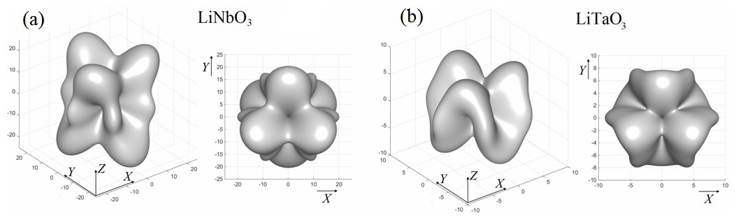
Figure 2The extreme surfaces for LiNbO3 (a) and LiTaO3 (b) crystals (isometric and top views). All values on the axes are in pC N.
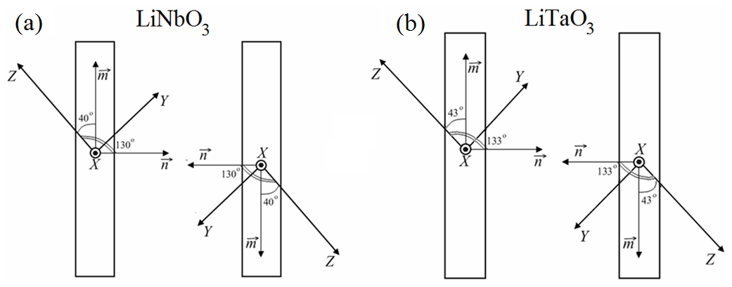
Figure 3The optimal orientations of bimorph plates for LiNbO3 (a) and LiTaO3 (b); x, y, and z are the axes of the crystal-physics system of coordinates.
The optimization was performed using the approach developed for the analysis of induced and nonlinear optical effects in crystals (see, e.g., Buryy et al., 2013). This approach is based on the construction and analysis of the special-type (extreme) surfaces. Such surfaces comprise all possible maxima of the investigated effect which are achieved by determination of the optimal orientations of the determinant factor (electric field) n for all possible directions of crystal orientation determined by vector m. If the direction of n is defined by the angles θn, ϕn of the spherical coordinate system and the direction of m by the angles θm, ϕm, then δl (the objective function of the optimization) will depend on four variables θn, ϕn, θm, and ϕm. Now for each pair of angles θm, ϕm we can determine such angles θn max, ϕnmax which maximize the value of δl. Obviously, these angles depend on θm, ϕm, θn max ≡θn max(θm, ϕm), and ϕnmax=ϕn max(θm, ϕm), and δl can be considered a function of two variables θm and ϕm. The dependence δlmax(θm, ϕm) at θn=0 … π, ϕn=0 … 2π can be represented as a surface; the designation “δlmax” used here emphasizes that the dependence of δlmax is obtained after maximizing on θn, ϕn (parameters of the optimization). In accordance with the rule of determination of δlmax, we use the term “extreme” for such a surface. Thus the value of δlmax determines the length of the radius vector of this surface for the given direction of m. The angles θn, ϕn are varied during the optimization process in such a manner that the condition n⊥m is always fulfilled; i.e., the vector n rotates in the plane perpendicular to m. Subsequently, the piezoelectric extreme surface is given by
where nmax is the vector from a set of vectors n⊥m which maximize the value of δl for the fixed direction of m. The piezoelectric coefficients used in these calculations are indicated in Table 1. The extreme surfaces for both LiNbO3 and LiTaO3 crystals are shown in Fig. 2. As is mentioned above, each point of the surface represents the maximal value of the relative expansion δlmax for a given θ and ϕ, but the highest possible expansions correspond to the global maxima of the relative expansion, which, in their turn, correspond to the points which are the outermost from the origin of coordinates. The optimal directions of m and n as well as the corresponding values of δlmax are indicated in Table 1. It should be noted that alternatively the optimization can also be performed when the angles θ, ϕ coincide with θn, ϕn and the angles θm, ϕm are considered the variables. The obtained results for both optimization cases are the same; therefore, the latter case is not shown.
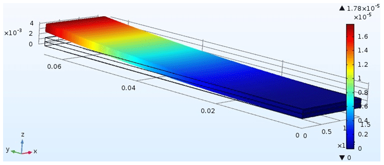
Table 1The position and values of global maxima of the relative elongation δlmax for LiNbO3 and LiTaO3 crystals.
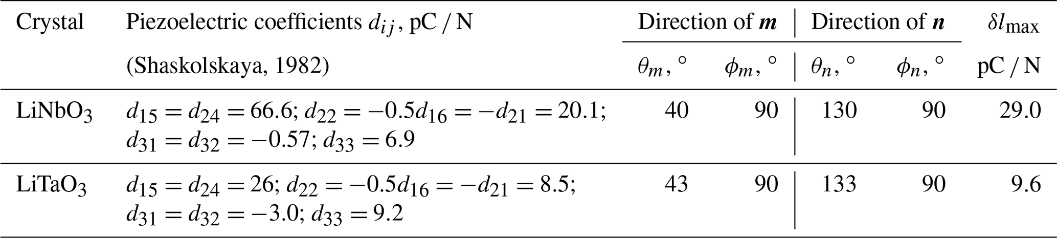
Only one set of the angles is given for each crystal. Other sets can be obtained using the symmetry elements of the point group (point group of crystals (3m) + center of inversion).
Table 2The displacements of actuators (µm) under the excitation voltage of 300 V.
Since the maximal displacement of the actuator occurs when one plate maximally expands and the other one maximally compresses, the plates of the actuator have to be rotated relative to each other by 180∘ in the YOZ plane. It is equivalent to application of the electric field of the opposite polarity to the plates. In this case the absolute values of the displacement will be exactly the same but with different signs. These optimal configurations of actuators are shown in Fig. 3. As is seen from the figure, they are almost similar for both LiNbO3 and LiTaO3: only the angles of rotation around the x axis show an insignificant difference (about 3∘).

Figure 5The dependencies of displacement on applied voltage for the actuators based on LiNbO3 (a) and LiTaO3 (b).
To determine the maximum extent of displacements of actuators, their simulation by the finite-element method was performed. In this simulation the geometry of actuators is similar to that used in our previous work (Buryy et al., 2019): width (x), length (y), and height (z) of each plate are 15, 65 and 0.75 mm, respectively; see Fig. 4 (dependence of actuator displacements on its geometry is analyzed in Buryy et al., 2019). The simulated excitation voltages are in the range from −300 to 300 V. Three different cases were considered: (i) the “initial” orientations of the plates – crystallographic z axes are perpendicular to the plates; (ii) the optimal orientations indicated in Table 1; (iii) y+127∘ and y+36∘ cuts for LiNbO3 and LiTaO3 correspondingly.
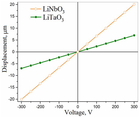
Figure 6The dependencies of calculated displacement on applied voltage for the optimized actuators based on LiNbO3 and LiTaO3.
The cases for comparison were chosen for the following reasons. Case (i) corresponds to the orientation of the already manufactured LiNbO3-based actuator (Buryy et al., 2019). Moreover, in this paper the dependencies of actuator displacements are theoretically analyzed with variations of actuator length (from 10 to 80 mm) and thickness (from 0.4 to 2.4 mm). Since the main peculiarities of these dependencies were revealed in Buryy et al. (2019), we do not repeat the same analysis here. Case (ii) corresponds to the optimal orientations determined in the current study (see Table 1). Case (iii) corresponds to the commercially available cuts of LiNbO3 and LiTaO3 characterized by the highest values of transversal piezoelectric coefficients (Matsunami et al., 2008; Kubasov et al., 2016).
The results of the simulation, i.e., the absolute values of displacements of bimorph plates, are shown in Figs. 5–6 and indicated in Table 2. As well as in Buryy et al. (2019), the dependencies of actuator displacement on excitation voltage are linear in all the studied voltage ranges, i.e., up to a field strength of 200 V/mm. As is shown, the optimal configuration of the actuator allows us to sufficiently increase the displacement value (with other parameters fixed): the displacement is 26 times higher for lithium niobate and 4.6 times higher for lithium tantalate compared to the actuator, studied in Buryy et al. (2019) (case (i)). Compared to the commercially available plates (case (iii)), the displacement increases for about 11 % for LiNbO3 and 67 % for LiTaO3.
The displacement of the LiNbO3 actuators with optimized orientation is about 3 times higher compared to that of LiTaO3; see Fig. 6. However, the displacement of the LiTaO3 actuator is 2 times higher when case (ii) is considered. So, in case the use of z-cut plates is desired from the technological point of view, the application LiTaO3 is preferable.
The obtained simulation results will be used for preparation of bimorph actuators with optimal orientations in the forthcoming research.
The actuators for precise positioning based on bimorph structure formed by joining lithium niobate and lithium tantalate plates of different crystallographic orientations are considered. To ensure the highest possible displacements of the actuator, the optimal orientations of their plates were determined by the extreme surfaces technique. The possible absolute values of displacements are determined by simulation using the finite-element method. It is shown that the optimal orientations of the long edges of the actuator plates are defined by the angles θm=40∘, ϕm=90∘ for LiNbO3 crystal and by θm=43∘, ϕm=90∘ for LiTaO3. The electric field is applied in the directions determined by the angles θn=130∘, ϕn=90∘ and θn=133∘, ϕn=90∘ for LiNbO3 and LiTaO3, respectively. The optimal configuration of the actuator allows us to sufficiently increase its displacement (with other parameters fixed): in 26 times for LiNbO3 and in 4.6 times for LiTaO3 compared to the previously manufactured actuator with the z axes of the plates perpendicular to the surface of bonding. In comparison with the commercially available LiNbO3 y+127∘ cut and LiTaO3 y+36∘ cut, the displacement increases for about 11 % for LiNbO3 and 67 % for LiTaO3. For the optimized design, the displacement of the LiNbO3 actuator is about 3 times higher than that of LiTaO3. However, for the case when the z axes of the plates are perpendicular to the bonding surface, the displacement is twice as high for the LiTaO3 actuator compared to LiNbO3.
All relevant data presented in the article are stored according to institutional requirements and as such are not available online. However, all data used in this paper can be made available upon request to the authors.
OB developed the methodology and software and determined the optimal orientations of the actuator plates. IIS and DS developed the design of the actuator. IIS and UY produced the experimental sample of the actuator. YS and HF developed the equipment and measured the actuator displacements. UY simulated the bimorph actuator and calculated the absolute values of its displacements. DS, SU and HF formulated the concept of the work. OB, YS and DS prepared the manuscript with contributions from all the co-authors.
The authors declare that they have no conflict of interest.
This article is part of the special issue “Sensors and Measurement Science International SMSI 2020”. It is a result of Sensor and Measurement Science International, Nuremberg, Germany, 22–-25 June 2020.
The authors from Clausthal University of Technology were supported by the Energie-Forschungszentrum Niedersachsen, Goslar, Germany.
The work was carried out in the framework of the joint German–Ukrainian project “Nanocrystalline piezoelectric compounds LiNb1−xTaxO3 for high-temperature applications” (M/48-2020) and project DB/MODUS (no. 0121U107736) of the Ukrainian Ministry of Education and Science. Further, research grants from the Deutsche Forschungsgemeinschaft (DFG, German Research Foundation, FR1301/42-1, SU1261/1-1) supported this work.
This open-access publication was funded by Clausthal University of Technology.
This paper was edited by Stefan J. Rupitsch and reviewed by one anonymous referee.
Antipov, V. V., Bykov, A. S., Malinkovich, M. D., and Parkhomenko, Y. N.: Formation of bidomain structure in lithium niobate single crystals by electrothermal method, Ferroelectrics, 374, 65–72, https://doi.org/10.1080/00150190802427127, 2008.
Buryy, O., Andrushchak, A., Kushnir, O., Ubizskii, S., Vynnyk, D., Yurkevych, O., Larchenko, A., Chaban, K., Gotra, O., and Kityk, A.: Method of extreme surfaces for optimizing the geometry of acousto-optic interactions in crystalline materials: Example of LiNbO3 crystals, J. Appl. Phys., 46, 083103, https://doi.org/10.1063/1.4792304, 2013.
Buryy, O., Sugak, D., Syvorotka, I., Yakhnevich, U., Suhak, Yu., Ubizskii, S., and Fritze, H.: Simulation, making and testing of the actuator of precise positioning based on bimorph plate of lithium niobate, Proc. of IEEE 15th International Conference on the Perspective Technologies and Methods in MEMS Design (MEMTECH), 22–26 May 2019, Polyana, Ukraine, 148–152, https://doi.org/10.1109/MEMSTECH.2019.8817401, 2019.
Bykov, A. S., Grigoryan, S. G., Zhukov, R. N., Kiselev, D. A., Ksenich, S. V., Kubasov, I. V., Malinkovich, M. D., and Parkhomenko, Yu. N.: Formation of bidomain structure in lithium niobate plates by the stationary external heating method, Russ. Microelectronics, 43, 536–542, https://doi.org/10.1134/S1063739714080034, 2014.
Jiang, W., Mayor, F. M., Patel, R. N., McKenna, T. P., Sarabalis, C. J., and Safavi-Naeini, A. H.: Nanobenders as efficient piezoelectric actuators for widely tunable nanophotonics at CMOS-level voltages, Communications Physics, 3, 156, https://doi.org/10.1038/s42005-020-00412-3, 2020.
Kawamata, A., Hosaka, H., and Morita, T.: Non-hysteresis and perfect linear piezoelectric performance of a multilayered lithium niobate actuator, Sensor. Actuat. A-Phys., 135, 782–786, https://doi.org/10.1016/j.sna.2006.08.025, 2007.
Kubasov, I. V., Popov, A. V., Bykov, A. S., Temirov, A. A., Kislyuk, A. M., Zhukov, R. N., Kiselev, D. A., Chichkov, M. V., Malinkovich, M. D., and Parkhomenko, Y. N.: Deformation anisotropy of -cut single crystalline bidomain wafers of lithium niobate, Russ. Microelectronics, 46, 557–563, https://doi.org/10.1134/S1063739717080108, 2016.
Matsunami, Go, Kawamata, A., Hosaka, H., and Morita, T.: Multilayered LiNbO3 actuator for XY-stage using a shear piezoelectric effect, Sensor. Actuat. A-Phys., 144, 337–340, https://doi.org/10.1016/j.sna.2008.02.006, 2008.
Nakamura, K. and Shimizu, H.: Hysteresis-free piezoelectric actuators using LiNbO3 plates with a ferroelectric inversion layer, Ferroelectrics, 93, 211–216, https://doi.org/10.1080/00150198908017348, 1989.
Nakamura, K. and Yamada, K.: Ferroelectric domain inversion in LiNbO3 and its application to high-precision piezoelectric actuators, MRS Proceedings, 360, 21–29, https://doi.org/10.1557/proc-360-21, 1995.
Panda, P. K.: Review: environmental friendly lead-free piezoelectric materials, Journal of Material Science, 44, 5049–5062, https://doi.org/10.1007/s10853-009-3643-0, 2009.
Randles, A., Tanaka, S., and Esashi, M.: Lithium niobate bulk micromachining for medical sensors, Future Medical Engineering Based on Bionanotechnology, 495–504, https://doi.org/10.1142/9781860948800_0054, 2006.
Segel, J. E.: Piezoelectric Actuators, New York, USA, Nova Science Publishers Inc., Hauppauge, New York, USA, 2012.
Shaskolskaya, M. P. (Ed.): Acoustic crystals, Moscow, Nauka, 1982 (in Russian).
Shur, V. Ya., Baturin, I. S., Mingaliev, E. A., Zorikhin, D. V., Udalov, A. R., and Greshnyakov, E. D.: Hysteresis-free high-temperature precise bimorph actuators produced by direct bonding of lithium niobate wafers, Appl. Phys. Lett., 106, 053116, https://doi.org/10.1063/1.4907679, 2015.
Turutin, A. V., Vidal, J. V., Kubasov, I. V., Kislyuk, A. M., Malinkovich, M. D., Parkhomenko, Yu. N., Kobeleva, S. P., Pakhomov, O. V., Kholkin, A. L., and Sobolev, N. A.: Magnetoelectric metglas/bidomain y+140∘-cut lithium niobate composite for sensing fT magnetic fields, Appl. Phys. Lett., 112, 262906, https://doi.org/10.1063/1.5038014, 2018.
Uchino, K.: Ferroelectric Devices & Piezoelectric Actuators. Research Misconceptions and Rectifications, DeStech Publications, Inc., Lancaster, Pennsylvania, USA, 2017.
Ueda, M., Sawada, H., Tanaka, A., and Wakatsuki, N.: Piezoelectric actuator using a LiNbO3 bimorph for an optical switch, IEEE Symposium on Ultrasonics, 3, 1183–1186, https://doi.org/10.1109/ULTSYM.1990.171548, 1990.
Vijaya, M. S.: Piezoelectric Materials and Devices. Applications in Engineering and Medical Science, CRC Press, Boca Raton, Florida, USA, 2017.
Wakatsuki, N., Yokoyama, H., and Kudo, S.: Piezoelectric actuator of LiNbO3 with an integrated displacement sensor, Jpn. J. Appl. Phys., 37, 2970–2973, https://doi.org/10.1143/JJAP.37.2970, 1998.